STAN DANI - revista de materiale plastice
STAN DANI - revista de materiale plastice
STAN DANI - revista de materiale plastice

You also want an ePaper? Increase the reach of your titles
YUMPU automatically turns print PDFs into web optimized ePapers that Google loves.
Influence Factors on the Dimensional Accuracy<br />
of the Plastic Parts<br />
<strong>DANI</strong>EL <strong>STAN</strong>*, AUREL TULCAN, LILIANA TULCAN, TUDOR ICLANZAN<br />
Univ. Politehnica din Timisoara, Facultatea <strong>de</strong> Mecanica, Bd. M. Viteazul, Nr.1, 300222, Timisoara, Romania<br />
The paper <strong>de</strong>als with the shrinkage and warpage phenomenon briefly presenting the most important influence<br />
factors and their interaction involved in dimensional changes of injected plastic parts. The predictable<br />
tolerances, <strong>de</strong>sign strategy and the main required action are <strong>de</strong>bated for one final purpose: maximum and<br />
yet realistic accuracy of dimensional precision, in a cheapest, easy manufacturability and easy operating<br />
injection tool. Finally, there are presented some useful consi<strong>de</strong>rations for minimizing the effect of shrinkage<br />
and warpage in dimensional variance of injected plastic parts.<br />
Keywords: injection moulding, tolerance, shrinkage, warpage<br />
The <strong>de</strong>sign history of any engineering product reveals<br />
that most <strong>de</strong>signs are not right at the first time and,<br />
inevitably, the main problems result from poor tolerance<br />
capability and manufacturing capability.<br />
Generally in industrial manufacturing dimensional<br />
tolerance specification will govern the part cost and<br />
manufacturability and particularly at part and mould<br />
<strong>de</strong>sign, a special attention must be paid to a realistic<br />
prescription of tolerances.<br />
According to the industrial standards (e.g. DIN 16901),<br />
in terms of general tolerances and dimensions, a distinction<br />
is generally ma<strong>de</strong> between three mould quality classes [1]:<br />
- for “general-purpose” injection-moulding, with fast<br />
production cycles in simple working conditions, requiring<br />
a low level of quality control and low reject rates;<br />
- for a medium level technical injection moulding,<br />
consi<strong>de</strong>rably more costly since it imposes higher <strong>de</strong>mands<br />
on the mould and specific production conditions; requires<br />
frequent quality control checks, having an increased reject<br />
rates ;<br />
- for high-precision injection moulding, requires<br />
advanced manufacturing precision of the moulds, special<br />
production conditions and continuous quality control.<br />
The influence of mould cost on the individual parts costs<br />
is largely <strong>de</strong>pen<strong>de</strong>nt on proper correlation between the<br />
assessed production volume, the time interval over which<br />
the moul<strong>de</strong>d part will become obsolete and damping time<br />
for the mould. Normally moulds are amortized over 1 – 3<br />
years, involving several million parts.<br />
Besi<strong>de</strong> part shape and <strong>de</strong>sign and wall dimensions, the<br />
dimensional tolerance is also one of the most important<br />
influence factors on mould cost. Unnecessarily tight<br />
tolerances for example, can greatly increase costs by<br />
generating a large quantity of <strong>de</strong>fective mouldings.<br />
Technically, taking into account mould dimensions the<br />
following dimensional tolerances are associated with good<br />
moulding practice:<br />
– dimensions up to 150 mm:<br />
±0.15% for precision moulding<br />
±0.3% for technical moulding<br />
– dimensions above 150 mm:<br />
±0.25% for precision moulding<br />
±0.4% for technical moulding<br />
Mould manufacturing tolerances<br />
Thermoplastics, due to their specific behaviour (typically<br />
have high elongation and elasticity), do not permit the close<br />
tolerances that are specified for metals with their high<br />
rigidity, low elongation and low elasticity.<br />
For multicavity moulds, the tool making tolerances are<br />
important having a direct effect on the dimensional<br />
tolerance of the part.<br />
As an example, in an ordinary mould, for a mould<br />
dimension of 30 mm manufactured to within ±0,01 mm,<br />
experience has shown that dimensional consistency better<br />
than ±0,03 to ±0,04 mm cannot be expected for parts from<br />
different cavities in a single shot.<br />
The <strong>de</strong>signers play a key role not only in <strong>de</strong>fining the<br />
material and part <strong>de</strong>sign but also in <strong>de</strong>termining the costs<br />
of an injection-moul<strong>de</strong>d part, and they must also ensure<br />
commercially viable tolerance. For this, it is important to<br />
avoid excessively close tolerances for plastic components<br />
and to <strong>de</strong>fine the correct tolerance range of the final<br />
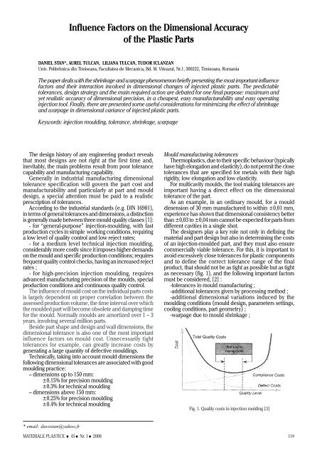
product, that should not be as tight as possible but as tight<br />
as necessary (fig. 1), and the following important factors<br />
must be consi<strong>de</strong>red, [2] :<br />
-tolerances in mould manufacturing ;<br />
-additional tolerances given by processing method ;<br />
-additional dimensional variations induced by the<br />
moulding conditions (mould <strong>de</strong>sign, parameters settings,<br />
cooling conditions, part geometry) ;<br />
-warpage due to mould shrinkage ;<br />
Fig. 1. Quality costs in injection molding [3]<br />
* email: davostan@yahoo.fr<br />
MATERIALE PLASTICE ♦ 45♦ Nr. 1♦ 2008 119
-it is also important to <strong>de</strong>ci<strong>de</strong> whether only a production<br />
tolerance is required or whether an operating tolerance is<br />
also necessary if the part dimensions are affected by<br />
service environment (moisture, thermal expansion, contact<br />
with chemicals).<br />
A commercially acceptable value for a production<br />
tolerance would be 0.25 to 0.3% <strong>de</strong>viation from the nominal<br />
dimension, but this must be checked against application<br />
requirements. When close tolerances are nee<strong>de</strong>d, it is<br />
important to consult with the injection moul<strong>de</strong>r or material<br />
supplier to see if the required tolerances are technically<br />
feasible and commercially appropriate.<br />
Choosing a plastic for a specific use can be a daunting<br />
task. Designers face a seemingly endless variety of resins<br />
and a lot of properties that <strong>de</strong>fine them. However, each<br />
market usually needs a unique set of properties for the<br />
plastics used in it, each product family needs particular<br />
plastics and additives.<br />
It has been assumed that for each process there is a<br />
fundamental level of inherent variability associated with<br />
processing the “i<strong>de</strong>al” <strong>de</strong>sign in realistic manufacturing<br />
conditions.<br />
The ITG refers to the International Tolerance Gra<strong>de</strong> of<br />
an industrial process and i<strong>de</strong>ntifies what tolerances a given<br />
process can produce for a given dimension. For injection<br />
moulding, typically procedure and common mould <strong>de</strong>sign,<br />
the ITG is about 9 to 14, [1,4], and the following formula:<br />
where T is the tolerance, [μm], D is the dimension, [mm])<br />
gives an expected tolerance not smaller than T = 22 μm,<br />
for a nominal dimension D = 10 mm and ITG = 9, the<br />
shrinkage being responsible for this limitation. The effects<br />
of shrinkage grow as part dimensions grow and the<br />
precision is smaller.<br />
Thus, holding a tolerance to ±(0,02÷0.05) mm is a<br />
realistic goal only for a small dimensions part (D < 30 mm),<br />
but could be a real problem for bigger dimensions, leading<br />
to special mould <strong>de</strong>sign and special working conditions.<br />
Un<strong>de</strong>r these circumstances, for small plastic parts, the<br />
mould equipment would be theoretically manufactured<br />
at a tenth of calculated value, at about T m<br />
= 2÷5 μm.<br />
Technically is accepted that plastic mould making<br />
equipment is not proper to generate dimensions with<br />
tolerances less than 1…2 μm. Even if its technological<br />
equipment is not <strong>de</strong>signed to hold these small tolerances,<br />
toolmakers sometimes makes “micro tooling” at<br />
(1)<br />
Fig. 2. Shrimkage and warpage of the plastic parts<br />
production-repeatability up to 2…5 μm, the lack in<br />
mouldmaking equipment precision being compensated by<br />
inventively and professional experience. Electro-discharge<br />
manufacturing and several other processes, including<br />
stereo-lithography, precision laser machining, chemical<br />
etching, metal spray and silicon wafer technology, are<br />
available to make such tooling.<br />
Shrinkage and warpage of the injected plastic parts<br />
Shrinkage or mould shrinkage reflects the rate of<br />
reduction from the mould cavity dimensions to the<br />
corresponding plastic part dimensions, due to the stress<br />
induced in material, and it’s an important information for<br />
concurrent <strong>de</strong>sign, for material substitution and for specific<br />
applications.<br />
Normally, the most important shrinkage and stress of<br />
the plastic part material will be noticed along the wall<br />
direction. Frequent flow direction changes and a complex<br />
geometry of the moul<strong>de</strong>d part could however lead to<br />
unexpected material stress having an effect on shrinkage<br />
and hence on tolerances and geometric precision. This<br />
non-uniform shrinkage can cause warpage and plastic partdistortion<br />
of the 3D part geometry (fig. 2), that can be<br />
significantly greater than the in-plane mould shrinkage<br />
value.<br />
Basically, material shrinkage, as physical property of<br />
every plastic material, is ascertained by the phase changes,<br />
particularly microstructure and the different <strong>de</strong>nsity of the<br />
polymer from the processing to the ambient temperature.<br />
Semi-crystalline materials are particularly prone to<br />
Fig. 3. Influence factors for shrinkage<br />
and part warpage [3, 5-7]<br />
120<br />
MATERIALE PLASTICE ♦ 45♦ Nr. 1♦ 2008
a. Materials shrinkage DSM specifications [8]<br />
relatively high thermal shrinkage and amorphous materials<br />
tend to shrink less.<br />
One of the main problems related to shrinkages is the<br />
lack-in-precision <strong>de</strong>finition of these and the great number<br />
of influence factors (fig. 3), that could affect the real part<br />
dimensions, [3, 5-7]. Therefore, the maximum and<br />
minimum values for various thermoplastics are indicated<br />
by the material suppliers (fig. 4), are gui<strong>de</strong>lines only.<br />
For a specific polymer gra<strong>de</strong>, a given part, mould and<br />
nest <strong>de</strong>sign, it is not possible to predict exact shrinkage<br />
values because this is extremely <strong>de</strong>pen<strong>de</strong>nt also on<br />
additives, on the part/mould <strong>de</strong>sign, and the processing<br />
conditions used to mould the part, on the geometry of the<br />
part and the flow pattern of the resin, so that in production<br />
an acceptable control of the final dimension(s) and<br />
warpage could be provi<strong>de</strong>d only by the variation of several<br />
injection parameters :<br />
- mould and melt temperature: it is too high, results in<br />
heat sinks due to shrinkage and if it is too cold, leads to<br />
moul<strong>de</strong>d-in stresses that may contribute to part warpage;<br />
- nest cooling speed;<br />
- hold time and injection hold pressure.<br />
If regrinding material, a special attention must be paid<br />
to the small changes in viscosity, <strong>de</strong>nsity, or composition<br />
that may occur when regrind is mixed with virgin material,<br />
if a material is used after it has been stored over an<br />
exten<strong>de</strong>d period of time, or a switch is ma<strong>de</strong> between<br />
different batches of the same material gra<strong>de</strong> and producer<br />
[3]. Small changes in lot-to-lot material properties can also<br />
induce dimensional instability, or inconsistencies in part<br />
weight among a batch of moul<strong>de</strong>d parts.<br />
Fig. 4. Variance of shrinkage with flow direction<br />
Table 1<br />
RECOMMANDED GATE TYPES [9]<br />
Shrinkage behaviour is also strongly affected by fibber<br />
reinforcement. For the basic material, the aligned<br />
macromolecular chains shrink more in the flow direction,<br />
while for reinforced materials the orientation of the glass<br />
fibres along the flow direction is responsible by<br />
substantially smaller shrinkage in flow direction than across<br />
flow direction (fig. 4).<br />
More over, the material shrinkage subject is not closed<br />
at <strong>de</strong>moulding moment. As a consequence of continued<br />
crystallisation and relaxation of moul<strong>de</strong>d-in stresses, where<br />
the resin moves towards a more stable state, in the next<br />
16÷24 h after the part has been ejected it follows a postmoulding<br />
shrinkage that must be taken into consi<strong>de</strong>ration<br />
and the dimensional control should be done long enough<br />
after injection moulding (48 h recommen<strong>de</strong>d).<br />
Mould <strong>de</strong>sign consi<strong>de</strong>rations<br />
Mould shrinkage starts when the polymer is injected into<br />
the mould cavity, so optimum mould <strong>de</strong>sign will choose<br />
the best gate(s) position, runner diameter, the smoothest<br />
flow path and best cycle time in or<strong>de</strong>r to prevent or to<br />
minimize the shrinkages and warpages across the whole<br />
part. Other elements to be consi<strong>de</strong>red inclu<strong>de</strong> cavity walls<br />
slope, cavity number, ribs, sli<strong>de</strong>s, cooling channels,<br />
placement of parting lines where the mould opens, ejectors<br />
and even the metal used for the mould.<br />
Runner and gate <strong>de</strong>sign should allow the molten plastic<br />
to flow smoothly to the limits of the cavity. For conventional<br />
cold runner tools, full-round runners are best because they<br />
provi<strong>de</strong> less resistance to flow, less contact surface area,<br />
MATERIALE PLASTICE ♦ 45♦ Nr. 1♦ 2008 121
cooling is minimized and therefore keep the material<br />
molten longer the shrinkage and post moulding induced<br />
stress being minimized.<br />
Next, <strong>de</strong>signers <strong>de</strong>ci<strong>de</strong> the gate type, adjust the size and<br />
position taking into account factors such as cavity pressure,<br />
mould-filling time, resin molecules and fibbers alignment<br />
ten<strong>de</strong>ncy.<br />
Gates can also be positioned to hi<strong>de</strong> flow lines that form<br />
on a part surface as resin passes through a gate or to<br />
relocate weld lines (weak areas where two or more melt<br />
streams meet after flowing around a core) to noncritical<br />
areas. The type of gate and the location of this relative to<br />
the part, can also affect the following:<br />
- part packing;<br />
- gate removal or vestige;<br />
- part aesthetics;<br />
- part dimensions, including substrate warpage<br />
A minimal set of elementary good-practice mould<br />
<strong>de</strong>sign consi<strong>de</strong>rations are to be taken into consi<strong>de</strong>ration :<br />
- start with small injection gates and the firsts injection<br />
tests will reveal the minimum cosmetic gate vestige to<br />
obtain best cavity fill. Large gates should be avoi<strong>de</strong>d.<br />
Generally the gate <strong>de</strong>pth should be around 35% of the<br />
part’s wall thickness at the gate entrance, less for easyflow<br />
material and maximum 50% for a viscous melt.<br />
A good starting point for the gate width should be 1.0-<br />
1.5 times the gate <strong>de</strong>pth. As a <strong>de</strong>sign tip, the gate area in<br />
the mould may be inclu<strong>de</strong>d as a removable insert to<br />
facilitate gate maintenance or modification ;<br />
- gates should be located at the heaviest cross section<br />
and/or so that the main flow direction will be aligned with<br />
the long axis.<br />
Generally the gate would be located at the thickest wall<br />
section, in or<strong>de</strong>r to facilitate part packing and minimize<br />
voids and sink, in a region where potential residual<br />
moul<strong>de</strong>d-in stresses around the gate will not affect part<br />
function or aesthetics, trying also to:<br />
-minimize obstructions in the flow path (flow around<br />
cores or pins);<br />
-minimize jetting (thin-walled components);<br />
-minimize flow marks in critical cosmetic areas;<br />
-minimize potential knit lines (particularly in<br />
components with two or more gates);<br />
- allow easy manual or automatic <strong>de</strong>gating.<br />
Furthermore, the shrinkage of the material in the<br />
direction of the flow will be different from that<br />
perpendicular to the flow. As a result, a rotating part will<br />
be somewhat elliptical rather than round. In or<strong>de</strong>r to<br />
eliminate this problem, “diaphragm gating” [7, 9] can be<br />
used which will cause the injection of material in all<br />
directions at the same time. The best, but most elaborate<br />
way is “multi-pin-gating” injection at several places<br />
symmetrically located. This will assure reasonable viscosity<br />
of the melt, creating as well as minimal and uniform<br />
shrinkage in all directions.<br />
For multi-cavity tools or/and multi-point injection, the<br />
cavity layout should be physically balanced so that the melt<br />
flows to each cavity in equal times un<strong>de</strong>r uniform pressure.<br />
An unbalanced runner lead to inconsistent part weights<br />
and dimensional variability of the part, even the nests are<br />
dimensionally appropriate.<br />
The wall thickness should be as uniform as possible to<br />
obtain the best moulding cycle time. Wall thickness ranging<br />
from 0,5 mm to 3 mm will ensure good rheological<br />
conditions in most injection applications. If the part<br />
requires the use of thick wall sections, they should be cored<br />
out both to minimize shrinkage problems and reduce the<br />
part weight and lower cycle time. Transitions between<br />
122<br />
different wall thickness should be gradual to reduce flow<br />
problems, such as turbulences, back fills and gas traps.<br />
The use of radii (0.5 mm minimum) in sharp corners<br />
also reduces localized stresses.<br />
A specific wall draft (0.5÷2) will be applied for the walls<br />
along the opening direction. Properly <strong>de</strong>signed <strong>de</strong>ep<br />
un<strong>de</strong>rcuts are possible if:<br />
- the part does not have sharp adjacent corners<br />
- advancing core is used when the mould opens<br />
- at ejection temperature the material is elastic enough<br />
and capable to <strong>de</strong>flect as it is ejected.<br />
If in service the stress or the <strong>de</strong>flection of the part un<strong>de</strong>r<br />
load are high, for a strengthen structure without thickening<br />
walls, ribs or other reinforcing features can be ad<strong>de</strong>d. The<br />
primary purpose of ribs in plastic <strong>de</strong>sign is to improve the<br />
stiffness of the structure by increasing sectional properties.<br />
Rib <strong>de</strong>sign (fig. 5) can affect part weight, cosmetics,<br />
warpage and moldability.<br />
Fig. 5. Exemple of ribs <strong>de</strong>sign [8, 9]<br />
Thick ribs can cause internal voids, shrinkage and<br />
ten<strong>de</strong>ncy to warp, as well as sink marks on the opposite<br />
part surface. For the same structural effect and ad<strong>de</strong>d mass<br />
and to avoid accentuated sink marks, few thinner ribs are<br />
better than a single large rib.<br />
Melt flow entering a thin rib can slow down and begin<br />
to freeze off while thicker wall sections are still filling.<br />
Deep, unventable blind pockets or tall ribs should be<br />
also avoi<strong>de</strong>d or a special attention will be granted to the<br />
venting holes that will be placed nearby.<br />
Parameters settings influence<br />
The most part of injection parameters could affect less<br />
or more the shrinkage, and through that, the precision and<br />
the final dimension of the part.<br />
After injection, while cooling down, the polymer starts<br />
to shrink. During the holding stage of the injection moulding<br />
cycle, shrinkage is compensated by material pushed into<br />
nest at a proper post-filling pressure. On the one hand, for<br />
example, a col<strong>de</strong>r mould leads to higher post-mouldings<br />
shrinkage and too short post injection parameters (hold<br />
pressure, hold time) involve an inconsistent and<br />
incomplete shrinkage, <strong>de</strong>formation of the moul<strong>de</strong>d part<br />
and to an alarming variability in part dimensions. The<br />
difference of temperature between the 2 plates of daylight<br />
section could lead also to important shrinkage and<br />
warpage (fig. 2).<br />
Generally, parts moul<strong>de</strong>d un<strong>de</strong>r recommen<strong>de</strong>d<br />
conditions (part and mould <strong>de</strong>sign, parameters settings and<br />
moulding conditions) are subject to small negligible shot<br />
to shot variations in dimensions due to the inherent trifling<br />
changes in machine parameters or conditions.<br />
The melting temperature is wi<strong>de</strong>ly accepted to be the<br />
main parameter affecting the rheology, and part<br />
dimensions, but the precise one-to-many relationships are<br />
MATERIALE PLASTICE ♦ 45♦ Nr. 1♦ 2008
Plane 1 = section through the rib<br />
Plane 2 = no rib in section<br />
Planes 3 and 4 = planes through the boss axis, in virtual <strong>de</strong>sign position<br />
Section in Plane 1 = proportional to the virtual shape, but affected by shrinkage<br />
Section in Plane 2 = dimensions are affected by shrinkage, warpage distortions<br />
Sections 3 and 4 = unpredictable warpage<br />
Fig. 6. Warpage in asymetrical plastic part<br />
generally not available prior to moulding. In symmetrical<br />
section, like section 1 or 2 from figure 6, a rib could<br />
minimize the internal stresses and the warpage leading to<br />
a stable shape similarly to the <strong>de</strong>signed one. Factor scale<br />
is the expression of the shrinkage and can be controlled<br />
from the earlier stage of tool <strong>de</strong>sign and/or later, managing<br />
the injection parameters. For asymmetrical geometry of<br />
the part, the situation became more intricate and a 3D<br />
inspection could reveal the warpage ten<strong>de</strong>ncies.<br />
A system view of the classical injection molding process<br />
[3, 10] reveal the complexity of this and the possibility to<br />
be <strong>de</strong>composed into five distinct but coupled and<br />
successive interacting stages: plastification, injection,<br />
packing, cooling, ejection. The output of each stage not<br />
only directly <strong>de</strong>termines the initial conditions of the next<br />
stage, but also influences the functionality of one or more<br />
others stages, finally affecting the qualities of the moul<strong>de</strong>d<br />
part.<br />
A fundamental difficulty in control of injection moulding<br />
is that none of the final moul<strong>de</strong>d part properties can be<br />
ascertained within the moulding cycle. And because it is<br />
not possible to achieve on-line information about material<br />
state, structure and aesthetic prior to mould opening and<br />
ejection of the part, part quality control is satisfied through<br />
a combination of on-line state variable control (through<br />
continuous control of the melt state) and off-line cycle-tocycle<br />
adjustment of the machine. But the control of<br />
injection moulding process is significantly challenged by<br />
the non-linear behaviour of the polymeric materials,<br />
dynamic and coupled process physics, and convoluted<br />
interactions between the mould geometry and final<br />
product quality attributes and there are not precisely known<br />
relation-ships between the machine input variables and<br />
final quality attributes. There is a lack of mo<strong>de</strong>ls to <strong>de</strong>fine<br />
the relationships from inputs to state variables and from<br />
state variables to outputs, more than that, the effects of<br />
the input variables could interact and the result could be<br />
less predictable, [10, 11]. Any change of one parameter<br />
has its own influences on the rheological behaviour of the<br />
melt, the shrinkage and stress of part material and on at<br />
least one other parameters.<br />
For establishing an efficient and applicable steady-state<br />
moulding cycle some basic consi<strong>de</strong>rations will be taken<br />
into account [3, 10, 11, 13]:<br />
- during start-up, the moulding parameters should be<br />
set at the mid-point of the recommendations from the raw<br />
data sheet;<br />
- shear rate adjustments should be the primary method<br />
used to control melt viscosity. Melt temperature<br />
adjustments should only be used to fine-tune the process;<br />
- for a minimized shrinkage, special attention should be<br />
paid to the temperature of the nest surfaces. An a<strong>de</strong>quate<br />
cooling will be able to minimize cycle time;<br />
- to minimize shrinkage issues, adjust second stage<br />
pressure as necessary to insure the melt is fully packed<br />
into the mould cavity;<br />
- if the lack of quality is due to the gate area, proceed to<br />
increase these or to fill the cavity through multiple injection<br />
points;<br />
- given the application <strong>de</strong>pen<strong>de</strong>nce of precision process<br />
control, the methodology for <strong>de</strong>veloping precision injection<br />
moulding process capabilities is based on a standard<br />
<strong>de</strong>cision making process in four steps : measure → analyse<br />
→ improve → control.<br />
For that, the process variables (al least the most<br />
important) could be observable and controllable;<br />
- for process repeatability, the primary criterion used was<br />
to see whether part quality could be reasonably controlled<br />
from shot to shot. Adjusting the cycle times (injection, part<br />
cooling, open close, mould cooling), a steady-state<br />
moulding cycle will be particularly <strong>de</strong>termined for each<br />
tool. Where nee<strong>de</strong>d and also possible, standard practices<br />
and suggestions will be formulated and refined for<br />
precision injection moulding;<br />
-the professional experience and preliminary<br />
experimental injection shots could lead to success in fixing<br />
the proper parameters.<br />
The shrinkage and warpage act less or more and thus<br />
the real shape of the tool does no longer correspond to its<br />
original and basic <strong>de</strong>sign. There are two correction ways<br />
to follow:<br />
MATERIALE PLASTICE ♦ 45♦ Nr. 1♦ 2008 123
- to accept the injection parameters data sheet (giving<br />
proper flow and filling conditions) and to correct the tool.<br />
Especially for symmetrically parts, capture first the actual<br />
contour of the injected part (digitise the surface of the part)<br />
and reshape the tool <strong>de</strong>sign to obtain a CAD data set<br />
reflecting the proper shape for the nest so that, after<br />
shrinkage and warpage, it will correspond to <strong>de</strong>mands<br />
then make the correction on tool.<br />
- to modify one or more parameters presented in figure<br />
3, to find a combination giving minimum values for<br />
shrinkage and warpage. First it must to be establish the<br />
process capability in<strong>de</strong>x, (Cpk), as a measure of how<br />
capable a process is of making parts that are within<br />
specifications [6, 12], for enabling the establishing of the<br />
process tolerances.<br />
Find next the critical factor and experience fine<br />
modifications till the product correspond to quality<br />
specifications. Once the proper combination revealed, a<br />
preventive attitu<strong>de</strong> and a proper strategy will be<br />
implemented. Procedures of Statistical Process control<br />
(SPC) and other proper quality assurance tools must be<br />
applied in mass production, [2, 6, 13].<br />
Additional variance sources<br />
Besi<strong>de</strong> the presented factors, there are more three<br />
others important sources of variability : the injection<br />
moulding machine <strong>de</strong>sign, environmental and human<br />
factors [10].<br />
Different injection cylin<strong>de</strong>r and clamp <strong>de</strong>sign of the<br />
varying moulding machines will induce very different<br />
machine dynamics, and provi<strong>de</strong> different levels of moul<strong>de</strong>d<br />
part quality for the same process set points. Even i<strong>de</strong>ntical<br />
machines, from the same manufacturer could have smaller<br />
differences in their controller due to internal controller<br />
variation relating to the shot size, injection velocity,<br />
switchover point, injection- and pack-pressure, etc.<br />
The physical environment will also introduce variation<br />
through interaction with the process. For instance, outdoor<br />
temperature may affect the effectiveness of the coolers<br />
that <strong>de</strong>termine the temperature of the plant water. Indoor<br />
temperature can likewise have significant effect on the<br />
mould temperature as well as the post-moulding behaviour<br />
of the moul<strong>de</strong>d parts.<br />
Humidity can affect the dryness of the polymeric<br />
material entering the barrel, introducing thus further quality<br />
inconsistencies.<br />
An interesting way to reduce, or eliminate, post-injection<br />
stress by modifying the interface polymer-metal properties<br />
could be the ultrasonic activated nozzle, [14, 15], is still<br />
<strong>de</strong>bated but few research teams from EU and Asia confirm<br />
his viability in articles from the last <strong>de</strong>ca<strong>de</strong>, [16, 17, 18].<br />
A particular effect of the ultrasonic activation, namely<br />
“the thermo-pellicular effect”, specific for the particularized<br />
activation conditions of the viscous elastically fluids un<strong>de</strong>r<br />
pressure can change the properties of the contact interface<br />
and offers the possibility for increasing the transfer velocity<br />
in the proximity of the wall. In extrusion for example, it<br />
was estimated an increasing of 80÷200% of the extrusion<br />
discharge and also of the productivity and next to the top<br />
of the ultrasonic horn we notice a local increase of the<br />
melt temperature with 40…80 o C [14].<br />
Human factor is also an important variance source. At<br />
least 3 persons are involved in mould processing: mould<br />
<strong>de</strong>signer, process engineers and the operator, and many<br />
others in the product <strong>de</strong>velopment project. Sometimes, the<br />
lack of quality and higher costs could have the significance<br />
of a misun<strong>de</strong>rstanding between these persons having not<br />
the same acceptance for “optimal processing conditions”.<br />
124<br />
Conclusions<br />
The best tolerances that can normally be met in injection<br />
moulding, with classical equipment is insi<strong>de</strong> of a total<br />
composite error between 0.05 and 0.15 mm, as shown in<br />
this paper. For high-precise small parts, the tolerance of<br />
whole dimensions can be controlled in tolerance ±<br />
0.05mm and particularly important dimension can be<br />
controlled in tolerance not less than ± 0.02 mm. Closer<br />
tolerances means higher tooling cost and fine control of<br />
the moulding conditions usually will be required.<br />
For the plastic part, “tolerance” may have different<br />
interpretations and these different un<strong>de</strong>rstandings must be<br />
aligned. For the part <strong>de</strong>signer it means functional<br />
limitations, to the mould <strong>de</strong>signer it means technology and<br />
tool fabrication variation allowance and the mould maker<br />
looks at it as production tolerance.<br />
Any over estimation in part quality levels requires<br />
increased investment, processing time, supplementary<br />
control and inspection costs and will lead to the ten<strong>de</strong>ncy<br />
to sacrifice production efficiency for the sake of quality.<br />
Design for moldability is the basis for efficient<br />
management and involve close coordination at least<br />
between the <strong>de</strong>signer, moul<strong>de</strong>r, and even raw material<br />
supplier. Team working capability and professional skills<br />
of the involved persons are important elements <strong>de</strong>ciding<br />
on the final results.<br />
If complex mouldings are to be produced to close<br />
tolerances is highly recommen<strong>de</strong>d to involve prototyping<br />
techniques in predicting the shrinkage and warpage<br />
behaviour in particular injection conditions, acting as<br />
suggested in present paper.<br />
If the part needs higher tolerances in (even) a small<br />
region, this location will be treated as a critical feature and<br />
will be used for the alignment of others less important<br />
features.<br />
Bibliography<br />
1.HASENAUER J., KUPER D., e.a - Top Ten Design Tips, http://plastics<br />
.dupont.com<br />
2.DAY D., Process Capable Tolerancing, Raines M. and Swift K.,<br />
CapraTechnology Ltd /UK<br />
3.KAZMER D., Precision process control of injection molding, Precision<br />
Injection Molding, Hanser Publishers /R.W. Friedl, J. Greener, 2005<br />
4.*** http://en.wikipedia.org/wiki/Injection_moulding<br />
5.RAUWENDAAL C., SPC: Statistical Process Control in Injection Molding<br />
and extrusion, Hanser Publishers, 2000, p. 88<br />
6.FETECAU C.,Mat. Plast., 42, nr.4, 2005, p. 290<br />
7.GHITA E., GILLICH G.R., BORDEASU I., e.a., Mat. Plast., 44, nr.2, 2007,<br />
p. 158<br />
8.DIMONIE D., RADOVICI C., e.a., Mat. Plast., 44, nr.2/2007, p.148<br />
9.*** http://www.dsm.com/en_US/html/<strong>de</strong>p/dimensionalstability.htm;<br />
10.*** http://www.sdp-si.com<br />
11.KAZMER D., DANAI K., Control of polymer processing, The<br />
mechanical Systems <strong>de</strong>sign Handbook: Mo<strong>de</strong>ling, Measurement and<br />
Control, CRC Press Inc, 2001<br />
12.CUPSA E., DRAGHICI G., Aca<strong>de</strong>mic J. of Manufacturing Engineering.,<br />
4, nr.2, 2006, p.23<br />
13. MANN, J.W. , Plastics Engg., 1974, 30, nr. 1, p.25<br />
14.<strong>STAN</strong> D.V. - Doctoral thesis, Universite Montpellier 2 /France, 1999;<br />
15. ICLANZAN T., <strong>STAN</strong> D., Mat. Plast., 42, nr.2, 2005, p.93<br />
16.YURONG C., HUILIN L., Influence of ultrasounds on the processing<br />
and structure of polypropylene during extrusion, Polymer Engg &<br />
Science, 42, Issue 7/2002, p.1534<br />
17.SHAOYUN G., YUNTAO L., e.a., Polymer International, 52, Issue 1/<br />
2003, p.68<br />
18. *** http://www.ultramelt.org, Ultra-Melt Project<br />
Manuscript received: 11.01.2008<br />
MATERIALE PLASTICE ♦ 45♦ Nr. 1♦ 2008