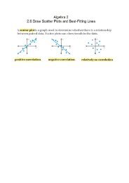
Machining Fundamentals
Machining Fundamentals
Machining Fundamentals

You also want an ePaper? Increase the reach of your titles
YUMPU automatically turns print PDFs into web optimized ePapers that Google loves.
<strong>Machining</strong> <strong>Fundamentals</strong><br />
Understanding Drawings<br />
Chapter 3
Drawings<br />
• Show the craft worker what to make and<br />
identify the standards that must be followed<br />
so the various parts will fit together<br />
properly.<br />
• The resulting parts will also be<br />
interchangeable with similar components on<br />
equipment already in service.
Drawings<br />
• Range from a simple freehand sketch, to<br />
detailed drawings for complex products.<br />
• American National Standards Institute<br />
(ANSI) |Developed symbols, lines, and<br />
figures<br />
• Symbols, lines, and figures on drawings are<br />
known as the language of industry.
Dimensions<br />
• A proper drawing includes all dimensions in<br />
proper relation to one another.<br />
• The dimensions are needed to produce the<br />
part or object.<br />
• Industries in the United States are in the<br />
process of converting to the metric system<br />
of measurement.
Fractional Dimensioning<br />
• Drawings using fractional dimensioning<br />
usually show objects that do not require a<br />
high degree of precision<br />
• Greater precision is indicated when<br />
dimensions are given in decimal parts of an<br />
inch.
Dual dimensioning<br />
• A system that employs the US Conventional<br />
system of fraction or decimal dimensions<br />
and metric dimensions on the same<br />
drawing.<br />
• If the drawing is intended primarily for use<br />
in the United States, the decimal inch will<br />
appear above the metric dimension.
Metric Dimensioning<br />
• All of the dimensions on the drawing are in<br />
the SI Metric system, usually in millimeters.<br />
• Until there is full conversion to metric in<br />
the United States, a conversion chart will<br />
appear on the drawing.
Information Included on<br />
Drawings
Materials<br />
• The general classification of materials to be<br />
used in the manufacture of an object may be<br />
indicated by the type of section line on the<br />
drawing.<br />
• Exact material specification is included in a<br />
section of the title block<br />
• May be found in the notes shown elsewhere<br />
on the drawing.
Surface Finishes<br />
• The quality of the surface finish (degree of<br />
surface smoothness) is important in the<br />
manufacture of products.<br />
• The smoother the finish of a machined surface, the<br />
more expensive it is to manufacture.<br />
• Check mark and number are used to indicate<br />
surface roughness in micro-inches or micro-meters
Surface Finishes<br />
• A machinist compares surface finishes to<br />
required specifications by using a surface<br />
roughness comparison standard as a guide.<br />
• If the surface finish is critical the finish is<br />
measured electronically with a device called<br />
a profilometer.
Tolerances<br />
• The control of dimensioning to achieve<br />
interchangeable manufacturing is known as<br />
tolerancing.<br />
• This controls the size of the features of a<br />
part.<br />
• A standard system of geometric<br />
dimensioning and tolerancing has been<br />
established.
Tolerances<br />
• Are allowances, either oversize or<br />
undersize, that are permitted when<br />
machining or making a part.<br />
• Fraction inch units the tolerance can be<br />
assumed to be +/- 1/64 unless otherwise<br />
indicated.<br />
• The plus and minus tolerance is called a<br />
bilateral tolerance.
Tolerances<br />
• When the tolerance is only plus or only<br />
minus it is called a unilateral dimension.
Quantity of Units<br />
• Shown on the drawing is the number of<br />
parts needed in each assembly.<br />
• Included with the job information received<br />
by the shop gives the total number of units<br />
to be manufactured.<br />
• This helps in ordering the correct amount of<br />
material for the job.
Drawing Scale<br />
• Drawings made other than actual size(1:1)<br />
are called scale drawings.<br />
• The scale is shown in a section of the title<br />
block.<br />
• A drawing made one-half size would have a<br />
scale of 1:2<br />
• A scale of 2:1 would mean that the drawing is<br />
twice the size of the actual part.
Assembly or Subassembly<br />
• Necessary to correctly fit the various parts<br />
together.<br />
• The term application is sometimes used in<br />
place of the term next assembly.
Revisions<br />
• Revisions indicate what changes were<br />
made to the original drawing and when they<br />
were made.
Names of the Object<br />
• A portion of the title block provides this<br />
information.<br />
• It tell the machinist the correct name of the<br />
piece.
Types of Prints
Blueprints<br />
• Blueprint is often used to refer to all types<br />
of prints.<br />
• An actual blueprint has white lines on a<br />
blue background<br />
• The blueprint process is seldom used today<br />
because of the time required to make a<br />
print.
Diazo Process<br />
• These are direct positive copies (dark lines<br />
on a white background) of the original<br />
drawing.<br />
• Often referred to as white-prints or bluelines.
Xerographic (electrostatic)<br />
Process<br />
• This process makes a copy of the original<br />
drawing<br />
• The print can be enlarged or reduced in size<br />
if necessary.<br />
• Full color copies can be made on some<br />
xerographic machines.
Microfilm Process<br />
• The original drawing is reduced by<br />
photographic means<br />
• Finished negatives can be stored in roll<br />
form or on cards<br />
• To produce a working print, the microfilm<br />
image is retrieved from files and enlarged<br />
onto photographic paper.
Computer-Generated Prints<br />
• Prints generated on a plotter from<br />
information stored electronically in<br />
computer memory.<br />
• This same information can also be used to<br />
control machine tools, using<br />
CAM(computer aided manufacturing).
Types of Drawings used in the<br />
Shop
Working Drawings<br />
• Detail drawings. These consist of a drawing<br />
of the part with dimensions, and other<br />
information for making the part.<br />
• Assembly drawings. These drawings show<br />
where and how the parts, described on<br />
detail drawings, fit into the completed<br />
assembly.
Working drawings<br />
• Subassembly drawings. Used to show the<br />
assembly of a small portion of the<br />
completed object.<br />
• Exploded pictorial drawings. A drawing<br />
with parts separated, put in proper<br />
relationship.
Parts List<br />
• Parts are identified by circled numbers and<br />
are listed in a note.<br />
• Some drawings will also include a parts list<br />
or bill of materials listing all of the parts<br />
used in the assembly.
Drawing Sizes<br />
• Companies usually store their drawings in<br />
the engineering department.<br />
• Engineers prepare drawings on standardsize<br />
sheets.<br />
• This simplifies the stocking handling, and<br />
storage of the completed drawings.
US Conventional Sheet Sizes<br />
• A size = 8 1/2” X 11”<br />
• B size = 11” X 17”<br />
• C size = 17” X 22”<br />
• D size = 22” X 34”<br />
• E size = 34” X 44”
SI Metric Sheet Sizes<br />
• A4 size = 210 X 297 mm<br />
• A3 size = 297 X 420mm<br />
• A2 size = 420 X 594 mm<br />
• A1 size = 594 X 841 mm<br />
• A0 size = 841 X 1189 mm
Geometric dimensioning and<br />
Tolerancing<br />
• A system that provides additional precision<br />
compared to conventional dimensioning.<br />
• It ensures that parts can be easily<br />
interchanged.
Definitions
Geometric Characteristic<br />
Symbols<br />
• They are employed to provide clarity and<br />
precision in communicating design<br />
specifications<br />
• These symbols are standardized by the<br />
American society of Mechanical Engineers<br />
(ASME).
Geometric Tolerance<br />
• A general term that refers to tolerances<br />
which control form, profile, orientation,<br />
location, and run-out.
Basic Dimension<br />
• A numerical value denoting the exact size,<br />
profile, orientation, or location of a feature.
True Position<br />
• Of a feature is its theoretically exact<br />
location as established by basic dimensions.
Reference Dimension<br />
• Is a dimension provided for information<br />
only.<br />
• It is not used for production or inspection<br />
purposes.
Datum<br />
• Is an exact point, axis, or plane.<br />
• It is the origin from which the location or<br />
geometric characteristic of features of a part<br />
is established.<br />
• It is identified by a solid triangle with an<br />
identifying letter.
Feature<br />
• Is a general term applied to a physical<br />
portion of a part, such as a surface, pin,<br />
hole, or slot.
Datum Feature<br />
• Is the actual feature of a part used to<br />
establish a datum.
Maximum Material Condition<br />
(MMC)<br />
• Is the condition in which the size of a<br />
feature contains the maximum amount of<br />
material within the stated limits of size.<br />
• Examples include a minimum hole diameter<br />
and maximum shaft diameter, both of which<br />
result in the greatest possible amount of<br />
material being used<br />
• MMC is indicated by an M within a circle.
Least Material Condition (LMC)<br />
• The condition in which the size of a feature<br />
contains the least amount of material within<br />
the stated tolerance limits<br />
• Examples include a maximum hole<br />
diameter and minimum shaft diameter.<br />
• LMC is indicated by an L within a circle.
Regardless of Feature Size (RFS)<br />
• Specifies that the size of a feature tolerance<br />
must not be exceeded.<br />
• RFS is assumed for all geometric tolerances<br />
unless otherwise specified.
Limits of size<br />
• The maximum and minimum sizes of a<br />
feature.
Actual size<br />
• The measured size of a part after it is<br />
manufactured.
Application of Geometric<br />
Dimensioning and Tolerancing<br />
• Datum identification symbol. A datum<br />
identifying symbol consists of a square<br />
frame that contains the datum reference<br />
letter.<br />
• All letters but I,O, and Q may be used.<br />
• A rectangular frame with the datum<br />
reference letter preceded and followed by a<br />
dash may be found on older drawings.
Application of Geometric<br />
Dimensioning and Tolerancing<br />
• Feature control frame. A feature control<br />
frame is used when a location or form<br />
tolerance is related to a datum.<br />
• It contains the geometric symbol, allowable<br />
tolerance, and the datum reference letter.<br />
• It is connected to an extension line of the<br />
feature, a leader running to the feature, or<br />
below a leader-directed note of the feature.
Form Geometric Tolerances<br />
• Control flatness, straightness, circularity<br />
(roundness) and cylindricity.
Flatness<br />
• Is a measure of the variation of a surface<br />
perpendicular to its plane.<br />
• The flatness geometric tolerance specifies<br />
the two parallel planes within which all<br />
points of a surface must lie.
Straightness<br />
• Describes how closely the surface of an<br />
object is to a line.<br />
• A straightness geometric tolerance<br />
establishes a tolerance zone of uniform<br />
width along a line.
Circularity<br />
• Is characterized by any given cross section<br />
taken perpendicular to the axis of a cylinder<br />
or a cone, or through the common center of<br />
a sphere.<br />
• A circularity geometric tolerance specifies a<br />
tolerance zone bounded by two concentric<br />
circles, indicated on a plane perpendicular<br />
to the axis of a cylinder or a cone.
Cylindricity<br />
• Represents a surface in which all points are<br />
an equal distance from a common center.<br />
• The cylindricity geometric tolerance<br />
establishes a tolerance zone that controls the<br />
diameter of a cylinder throughout its entire<br />
length.
Profile Geometric Tolerances<br />
• Controls the outline or contour of an object<br />
and can be represented by an external view<br />
or by a cross section through the object.<br />
• It is a boundary along the true profile in<br />
which elements of the surface must be<br />
contained.
Profile Line Geometric Tolerance<br />
• A two-dimensional (cross-sectional)<br />
tolerance zone extending along the length of<br />
the element.<br />
• It is located using basic dimensions.
Profile Surface Geometric<br />
Tolerance<br />
• Is three dimensional and extend along the<br />
length and width of the surface.<br />
• For proper orientation of the profile, a<br />
datum reference is usually required.
Orientation Geometric<br />
Tolerances<br />
• Control the degree of parallelism,<br />
perpendicularity, or angularity of a feature<br />
with respect to one or more datum's.
Angularity<br />
• Is concerned with the position of a surface<br />
or axis at a specified angle to a datum plane<br />
or axis.<br />
• The specified angle must be other than 90<br />
degrees.
Angularity Geometric Tolerance<br />
• Establishes a tolerance zone defined by two<br />
parallel lines, planes, or a cylindrical zone<br />
at a specified basic angle other than 90<br />
degrees.
Perpendicularity Geometric<br />
Tolerance<br />
• Specifies a tolerance zone at right angles to<br />
a given datum or axis.<br />
• It is described by two parallel lines, planes,<br />
or a cylindrical tolerance zone.
Parallelism<br />
• Describes how close all elements of a line<br />
or surface are to being parallel to a given<br />
datum plane or axis.
Parallelism Geometric Tolerance<br />
• Is a tolerance zone defined by two lines<br />
parallel to a datum within which the<br />
elements of a surface or axis must lie.
Location Geometric Tolerances<br />
• Are employed to establish the location of<br />
features and datum's<br />
• The define the zone within which the<br />
center, axis, or center plane of a feature may<br />
vary from the true position.<br />
• Also know as positional tolerances
Concentricity<br />
• Defines the relationship between the axes of<br />
two or more of an objects cylindrical<br />
features.
Concentricity Geometric<br />
Tolerance<br />
• Is express as a cylindrical tolerance zone.<br />
• The axis or center point of this zone<br />
coincides with a datum axis.
Symmetry<br />
• Indicate equal or balanced proportions on<br />
either side of a central plane or datum.
Symmetry Geometric Tolerance<br />
• Is a zone within which a symmetrical<br />
surfaces align with the datum of a center<br />
plane or axis.
Run-out Geometric Tolerances<br />
• Total run-out controls circularity,<br />
straightness, angularity, and cylindrically of<br />
a part when applied to surfaces rotated<br />
around a datum axis.<br />
• Circular run-out is applied to features<br />
independently and controls circularity of a<br />
single circular cross section
Summary<br />
• Geometric dimensioning and tolerancing is<br />
far more involved that described in this<br />
presentation. If you wish more information<br />
on this you may study a copy of ASME<br />
Y14.5M-1994, or enroll in a class on<br />
geometric dimensioning and tolerancing at<br />
the college of your choice.
Questions