Pentek RO-3000 Instruction Manual - Water Filters
Pentek RO-3000 Instruction Manual - Water Filters
Pentek RO-3000 Instruction Manual - Water Filters

You also want an ePaper? Increase the reach of your titles
YUMPU automatically turns print PDFs into web optimized ePapers that Google loves.
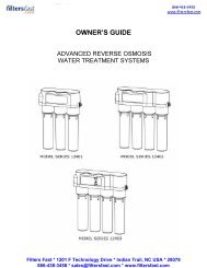
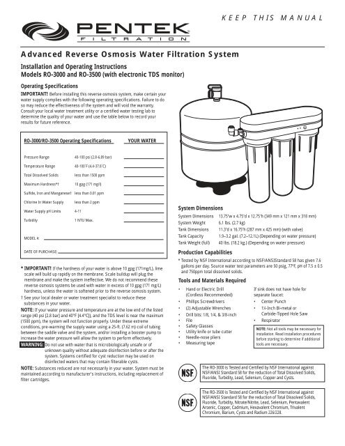
KEEP THIS MANUAL<br />
Advanced Reverse Osmosis <strong>Water</strong> Filtration System<br />
Installation and Operating <strong>Instruction</strong>s<br />
Models <strong>RO</strong>-<strong>3000</strong> and <strong>RO</strong>-3500 (with electronic TDS monitor)<br />
Operating Specifications<br />
IMPORTANT! Before installing this reverse osmosis system, make certain your<br />
water supply complies with the following operating specifications. Failure to do<br />
so may reduce the effectiveness of the system and will void the warranty.<br />
Consult your local water treatment utility or a certified water testing lab to<br />
determine the quality of your water and use the table below to record your<br />
results for future reference.<br />
<strong>RO</strong>-<strong>3000</strong>/<strong>RO</strong>-3500 Operating Specifications<br />
YOUR WATER<br />
Pressure Range<br />
Temperature Range<br />
Total Dissolved Solids<br />
Maximum Hardness*†<br />
Sulfide, Iron and Manganese†<br />
40-100 psi (2.8-6.89 bar)<br />
40-100˚F (4.4-37.8˚C)<br />
less than 1500 ppm<br />
10 gpg (171 mg/l)<br />
less than 0.01 ppm<br />
Chlorine In <strong>Water</strong> Supply<br />
<strong>Water</strong> Supply pH Limits 4-11<br />
Turbidity<br />
MODEL #:<br />
DATE OF PURCHASE:<br />
less than 2 ppm<br />
1 NTU Max.<br />
* IMPORTANT! If the hardness of your water is above 10 gpg (171mg/L), lime<br />
scale will build up rapidly on the membrane. Scale buildup will plug the<br />
membrane and make the system ineffective. We do not recommend these<br />
reverse osmosis systems be used with water in excess of 10 gpg (171 mg/L)<br />
hardness, unless the water is softened prior to the reverse osmosis system.<br />
† See your local dealer or water treatment specialist to reduce these<br />
substances in your water.<br />
NOTE: If your water pressure and temperature are at the low end of the listed<br />
range (40 psi [2.8 bar] and 40°F [4.4°C]), and the TDS level is near the maximum<br />
(1500 ppm), the system will not function properly. Under these extreme<br />
conditions, pre-warming the supply water using a 25-ft. (7.62 m) coil of tubing<br />
between the saddle valve and the system, and/or installing a booster pump to<br />
increase the water pressure will allow the system to perform effectively.<br />
WARNING: Do not use with water that is microbiologically unsafe or of<br />
unknown quality without adequate disinfection before or after the<br />
system. Systems certified for cyst reduction may be used on<br />
disinfected waters that may contain filterable cysts.<br />
NOTE: Substances reduced are not necessarily in your water. System must be<br />
maintained according to manufacturer's instructions, including replacement of<br />
filter cartridges.<br />
System Dimensions<br />
System Dimensions 13.75"w x 4.75"d x 12.75"h (349 mm x 121 mm x 318 mm)<br />
System Weight 6.1 lbs. (2.7 kg)<br />
Tank Dimensions 11.3"d x 16.75"h (287 mm x 425 mm) (with valve)<br />
Tank Capacity 1.9–3.2 gal. (7.2–12.1L) (Depending on water pressure)<br />
Tank Weight (full) 40 lbs. (18.2 kg.) (Depending on water pressure)<br />
Production Capabilities<br />
* Tested by NSF International according to NSF/ANSIStandard 58 has given 7.6<br />
gallons per day. Source water test parameters are 50 psig, 77ºF, pH of 7.5 ± 0.5<br />
and 750ppm total dissolved solids.<br />
Tools and Materials Required<br />
• Hand or Electric Drill<br />
(Cordless Recommended)<br />
• Phillips Screwdrivers<br />
• (2) Adjustable Wrenches<br />
• Drill bits: 1/8, 1/4, & 3/8-inch<br />
• File<br />
• Safety Glasses<br />
• Utility knife or tube cutter<br />
• Needle-nose pliers<br />
• Measuring tape<br />
If sink does not have hole for<br />
separate faucet:<br />
• Center Punch<br />
• 1 1 ⁄4-Inch Bi-metal or<br />
Carbide-Tipped Hole Saw<br />
• Respirator<br />
NOTE: Not all tools may be necessary for<br />
installation. Read installation procedures<br />
before starting to determine if additional<br />
tools are necessary.<br />
The <strong>RO</strong>-<strong>3000</strong> is Tested and Certified by NSF International against<br />
NSF/ANSI Standard 58 for the reduction of Total Dissolved Solids,<br />
Fluoride, Turbidity, Lead, Selenium, Copper and Cysts.<br />
The <strong>RO</strong>-3500 is Tested and Certified by NSF International against<br />
NSF/ANSI Standard 58 for the reduction of Total Dissolved Solids,<br />
Fluoride, Turbidity, Nitrate/Nitrite, Lead, Selenium, Pentavalent<br />
Arsenic, Copper, Cadmium, Hexavalent Chromium, Trivalent<br />
Chromium, Barium, Cysts and Radium 226/228.
General Precautions<br />
WARNING: The <strong>RO</strong>-<strong>3000</strong> and <strong>RO</strong>-3500 systems contain a replaceable<br />
membrane critical to the efficiency of the system. Replacement of<br />
the reverse osmosis membrane should be with one of identical<br />
specifications, as defined by the manufacturer, to assure the same<br />
efficiency and contaminant reduction performance.<br />
WARNING: The <strong>RO</strong>-<strong>3000</strong> and <strong>RO</strong>-3500 systems contain a replaceable<br />
membrane, critical for the effective reduction of total dissolved<br />
solids. Product water should be tested periodically to verify that<br />
the system is working properly.<br />
WARNING: The <strong>RO</strong>-3500 is acceptable for treatment of influent concentrations<br />
of no more than 27 mg/L nitrate and 3 mg/L nitrite in combination<br />
measured as N and is certified for nitrate/nitrite reduction only for<br />
water supplies with a pressure of 40 psig (280 kPa) or greater.<br />
WARNING: The <strong>RO</strong>-3500 shall only be used for arsenic reduction on<br />
chlorinated water supplies containing detectable residual free<br />
chlorine at the system inlet. <strong>Water</strong> systems using an in-line<br />
chlorinator should provide a one-minute chlorine contact time<br />
before the <strong>RO</strong> system.<br />
WARNING: The Reverse Osmosis (<strong>RO</strong>) system will not protect against diseasecausing<br />
bacteria or remove naturally-occurring harmless bacteria.<br />
CAUTION: The <strong>RO</strong>-<strong>3000</strong> and <strong>RO</strong>-3500 systems must be protected against<br />
freezing which can cause the filter housing to crack and water<br />
leakage.<br />
CAUTION: Because of the product's limited service life and to prevent costly<br />
repairs or possible water damage, we strongly recommend that<br />
the filter housings be replaced every ten years. If your housing has<br />
been in use for longer than this period, it should be replaced<br />
immediately.<br />
Date the bottom of any new filter housing to recommend the next<br />
replacement date.<br />
CAUTION: Do not use Plumber’s Putty in the installation of this product as it<br />
may cause cracking of the filter housing threads.<br />
NOTE:<br />
• Your water must be within required limits for satisfactory operation. If not,<br />
your membrane life may be shortened and your warranty will be voided (see<br />
Operating Specifications on page 1).<br />
• Install on cold water line only.<br />
• Make certain that installation complies with all state and local laws and<br />
regulations.<br />
• The reverse osmosis membrane and replacement cartridges included with<br />
this system have limited service lives. Changes in taste, odor, and color of<br />
the filtered water indicate that the cartridge(s) and/or membrane should be<br />
replaced (see Maintenance on page 10). On the monitored model (<strong>RO</strong>-3500)<br />
the green light indicates optimum performance while the amber light<br />
indicates that the membrane is in need of changing.<br />
• During extended periods of non-use (such as during a vacation), remove the<br />
membrane from the membrane housing and place it in a sealed plastic bag.<br />
Store membrane in refrigerator for future use. DO NOT FREEZE.<br />
• If system stands for more than 2 to 3 days without being used, the storage<br />
tank should be emptied.<br />
Membrane Precautions<br />
CAUTION: Chlorine will destroy the Reverse Osmosis membrane. If you use<br />
these <strong>RO</strong> systems with a chlorinated or periodically-chlorinated<br />
water supply, it is ABSOLUTELY NECESSARY to use a carbon prefilter<br />
(such as the USL-NCR cartridge, included with the system).<br />
This carbon pre-filter should be changed at least every 4 months<br />
to avoid chlorine breakthrough. See warranty for disclaimers and<br />
limitations that apply to the <strong>RO</strong> membrane.<br />
NOTE: To make sure no chlorine is present in the water that reaches the<br />
membrane, you may want to use a chlorine test kit to check the<br />
reject water that flows from the membrane to the drain. No chlorine<br />
should be detected.<br />
How Reverse Osmosis Works<br />
The <strong>Pentek</strong> <strong>RO</strong>-<strong>3000</strong> and <strong>RO</strong>-3500 use a semi-permeable membrane to reduce<br />
dissolved salts, improving the taste and odor of your water. The <strong>RO</strong> membrane is<br />
made of multiple layers of micron-thin film wound around a hollow center core.<br />
<strong>Water</strong> molecules can pass through the membrane, while dissolved salts are<br />
rejected. The <strong>Pentek</strong> <strong>RO</strong>-<strong>3000</strong> and <strong>RO</strong>-3500 systems feature triple-filter action.<br />
Your household water supply is pre-filtered to reduce dirt and chlorine that may<br />
foul the membrane. The <strong>RO</strong> membrane separates this pre-filtered water into<br />
P<strong>RO</strong>DUCT WATER and REJECT WATER. Your household water pressure forces<br />
the product water through the membrane and into the storage tank. Dissolved<br />
salts cannot pass through the membrane and are sent to the drain as reject<br />
water. When you open the <strong>RO</strong> faucet, product water is drawn from the storage<br />
tank through a post-polishing filter. The post-polishing filter takes out any<br />
remaining taste or odor in the water and provides you and your family with<br />
cleaner, great-tasting water.<br />
The <strong>RO</strong>-<strong>3000</strong> and <strong>RO</strong>-3500 systems also feature an auto shut-off valve, which<br />
shuts off the system once the pressure in the storage tank reaches 2/3 of the<br />
incoming water pressure (your household water pressure). When you open the<br />
faucet to draw water from the storage tank, the pressure inside the tank drops<br />
and the auto shut-off valve opens. The system then begins to operate,<br />
replenishing the water you took from the storage tank. For each gallon of water<br />
produced, 7 gallons are discharged as reject water. The storage tank can hold<br />
up to 3.2 gallons of water at a time, more than enough for the average family's<br />
drinking and cooking needs.<br />
When used under operating conditions specified on page 1 of the manual, your<br />
Reverse Osmosis membranes should last 12-24 months.<br />
NOTE: The <strong>RO</strong>-3500 unit will indicate a need for a membrane change with<br />
an amber light, see Light Indicator Readings on page 9 for details.<br />
The precise life span of your system's membrane will depend on the quality of<br />
the water entering the system and the frequency with which you use it. Frequent<br />
use prevents the dissolved salts from building up on the membrane as scale. The<br />
more water the system is required to produce, the longer the membrane will last.<br />
You may wish to find a variety of uses for your system in order to prolong the life<br />
of the membrane. The life of the membrane will also depend upon the regularity<br />
with which you replace the pre-filter cartridge in the system.<br />
Page 2
Replacement Parts<br />
A <strong>RO</strong>R Replacement Cartridge Kit 155923<br />
B <strong>RO</strong>M-230T Membrane (<strong>RO</strong>-<strong>3000</strong>) 155854<br />
C <strong>RO</strong>M-230TN Membrane (<strong>RO</strong>-3500) 155855<br />
D Nitrate/Nitrite Test Kit (<strong>RO</strong>-3500) 144925<br />
E TDS Test Kit (<strong>RO</strong>-<strong>3000</strong>) 150530<br />
F Manifold Cover 144747<br />
G Monitor (<strong>RO</strong>-3500) 157845<br />
H Housing o-ring (OR-233) 151231<br />
I Left and Right Housing 153126<br />
J Middle (Membrane) Housing 153158<br />
K Drinking <strong>Water</strong> Faucet 144839<br />
L Housing Wrench 150424<br />
M Auto Shut-Off Assembly 144653<br />
N 3/8-Inch Elbow 144764<br />
O 1/4- Inch Elbow 143370<br />
P Drain Clamp Assembly 144616<br />
Q Saddle Valve 144730<br />
R Membrane Locking Device 144847<br />
S Tank Valve 144829<br />
T Storage Tank with Stand 144165<br />
For replacement parts contact your nearest <strong>Pentek</strong> Filtration dealer or call 800-645-0267<br />
A B C E<br />
D<br />
F<br />
L<br />
G<br />
K<br />
H<br />
I J I<br />
S<br />
M<br />
N<br />
O<br />
T<br />
P Q R<br />
Page 3
Installation<br />
• Read all installation and operating instructions before installing and using your <strong>RO</strong> system.<br />
• Numbered diagrams correspond with numbered steps.<br />
Drinking <strong>Water</strong> Faucet<br />
Blue<br />
Drain<br />
Clamp<br />
White<br />
Red<br />
Saddle Valve<br />
Tank<br />
Valve<br />
Green<br />
Post-polishing<br />
Filter Housing<br />
Membrane<br />
Housing<br />
Pre-filter<br />
Housing<br />
Cold<br />
<strong>Water</strong><br />
White<br />
Manifold<br />
Cover<br />
Manifold<br />
Optional Tank Installation<br />
Storage Tank<br />
1. Installing the Saddle Valve<br />
WARNING: Use of a hand drill is recommended. To protect yourself from serious injury or<br />
fatal shock when using an electric drill, be sure the drill and the outlet it is<br />
plugged into are properly grounded. When using a drill, follow the<br />
manufacturer’s guidelines and procedures.<br />
NOTE: Saddle valve must be installed on a 2-inch long, straight-walled section of 3/8-<br />
inch to 7/8-inch steel, brass, copper, or PVC pipe. Call Technical Support if<br />
installing on braided or flexible tubing.<br />
1<br />
D<br />
B<br />
(A) Turn off cold water supply.<br />
(B) Turn on the cold water faucet before starting installation. Place a tray or towels under the<br />
cold water line to catch excess water.<br />
(C) Drill a 1/8-inch hole in cold water line. Remove any burrs with sandpaper or file.<br />
(D) Turn handle on saddle valve clockwise to expose lance no more than 3/16-inch beyond<br />
black rubber gasket.<br />
E<br />
2"<br />
C<br />
(E) Place saddle valve body over hole in cold water line so lance fits into hole.<br />
(F) Attach back plate of clamp and tighten bolts evenly and firmly so brackets are parallel.<br />
F<br />
(G) Turn handle on saddle valve clockwise to closed position. Leave closed until installation is<br />
complete.<br />
A<br />
G<br />
Page 4
Installation Continued<br />
2. Selecting the Faucet Location<br />
The drinking water faucet should be positioned with function, convenience and appearance in<br />
mind. An adequate flat area is required to allow faucet base to rest securely. The faucet fits<br />
through a 1 1 ⁄4-inch hole. Most sinks have pre-drilled 1 1 ⁄2-inch or 1 3 ⁄8-inch diameter holes<br />
designed for spray hoses. The drinking water faucet may be installed using one of these holes,<br />
despite their larger size. If these pre-drilled holes cannot be used or are in an inconvenient<br />
location, it will be necessary to drill a 1 1 ⁄4-inch hole in the sink or through countertop next to<br />
the sink for the faucet.<br />
3. Drilling the Faucet Hole<br />
CAUTION: This procedure may generate dusts which can cause severe irritation if inhaled<br />
or come in contact with the eyes. The use of safety glasses and respirator for<br />
this procedure is recomended.<br />
CAUTION: DO NOT ATTEMPT TO DRILL TH<strong>RO</strong>UGH AN ALL-PORCELAIN OR PORCELAIN-<br />
COATED SINK. For applications on these types of sinks we recommend using the<br />
sprayer hole or mounting the faucet through the countertop.<br />
CAUTION: When drilling through a countertop make sure the area below the drilled area is<br />
free of wiring and piping. Make certain that you have ample room to make the<br />
proper connections to the bottom of the faucet.<br />
CAUTION: Do not drill through a countertop that is more than 1-inch thick.<br />
CAUTION: Do not attempt to drill through a tiled, marble, granite or similar countertop.<br />
Consult a plumber or the countertop manufacturer for advice or assistance.<br />
The following instructions apply to stainless steel sinks only.<br />
(A) Line bottom of sink with newspaper to prevent shavings, parts or tools from falling down<br />
drain.<br />
(B) Place masking tape over the area to be drilled to prevent scratches if drill bit slips.<br />
(C) Mark point with center punch. Use a 1/4-inch drill bit to drill a pilot hole through sink.<br />
(D) Use a 1 1 ⁄2-inch hole saw to enlarge hole. Smooth rough edges with a file.<br />
4. Mounting the Faucet<br />
(A) Loosen brass stem-nut on faucet, remove metal "C" disc.<br />
(B) Holding the faucet, feed the three tubes through the hole in the sink. Position the faucet<br />
handle at a desired location.<br />
(C) Center the faucet and slip "C" disc between the white spacer and the bottom of the<br />
counter or sink. Tighten the stem nut with a wrench until it is tight.<br />
(D) Making sure the faucet handle is in the down position, use a needle-nose pliers to pull the<br />
short plastic tube out of the top of the faucet base.<br />
NOTE: If handle should come off faucet base, make sure the T-Bar is parallel to the<br />
front of the faucet base before inserting handle. If T-Bar is not in the correct<br />
position, the faucet will not work properly.<br />
(E) Lubricate the o-rings on the bottom of the faucet spout with supplied silicone lubricant.<br />
Use lubricant sparingly.<br />
(F) Insert goose-neck spout into faucet base firmly.<br />
5. Installing the Drain Clamp<br />
NOTE: If you have a single-basin sink with a disposal unit, call Technical Support for<br />
options.<br />
NOTE: Before installing the drain clamp, check the drainpipes under the sink for<br />
corrosion. Corroded pipes should be replaced before continuing with<br />
installation.<br />
(A) Attach the drain clamp to a vertical section of the drainpipe, about 6-inches above the<br />
trap. Make sure the opening on the drain clamp is facing towards the drinking water<br />
faucet.<br />
(B) Using the fitting hole of the drain clamp as a guide, drill 1/4-inch hole through one side of<br />
the drainpipe.<br />
(C) Remove the drain clamp from the drainpipe and enlarge the hole with a 3/8-inch drill<br />
bit.Use a file to remove rough edges from the drilled hole.<br />
(D) Make sure the black rubber gasket is adhered to the inside of the drain clamp and place<br />
the drain clamp assembly over the drilled hole. Look through the hole and position the<br />
clamp so that the center of the clamp hole is slightly higher (about 1/16-inch) than the<br />
center of the drilled hole. (See figure 5 D on page 6). Tighten the clamp securely.<br />
(E) Screw the plastic compression nut onto the drain clamp until hand-tight. (See figure 5 E<br />
on page 6).<br />
3<br />
Pilot Hole<br />
C<br />
D<br />
1⁄4"<br />
1<br />
⁄4”<br />
C<br />
1<br />
1 1 ⁄4"<br />
A<br />
⁄4”<br />
D<br />
4<br />
A<br />
B<br />
C<br />
D<br />
E<br />
F<br />
5<br />
6"<br />
B<br />
Mounting Hole<br />
A<br />
C<br />
B<br />
Page 5
Installation Continued<br />
6. Connecting the Faucet to the Drain<br />
NOTE: THIS IS A GRAVITY DRAIN LINE. ANY LOOPS, KINKS OR SHARP BENDS MUST<br />
BE ELIMINATED BEFORE P<strong>RO</strong>CEEDING. FAILURE TO CREATE A STRAIGHT LINE<br />
TO THE DRAIN MAY RESULT IN REJECT WATER LEAKING TH<strong>RO</strong>UGH THE AIR<br />
GAP IN THE FAUCET ONTO THE COUNTERTOP AND BELOW THE FAUCET.<br />
(A) Align the white 3/8-inch tubing from the faucet with the compression nut on the drain<br />
clamp. Create as straight a path as possible with the tubing. Cut the tubing squarely below<br />
the nut and remove the internal and external burrs.<br />
(B) Loosen the compression nut two complete turns. Insert the tubing into the nut until it<br />
stops. Tighten with fingers, then tighten 1 to 2 turns with a wrench.<br />
7. Installation of Mounting Screws<br />
(A) If system is being installed under the kitchen sink, locate it on back or right wall. Make<br />
sure to allow ample space for installation. To change the filter cartridges, a minimum of 1 1 ⁄2<br />
inches of clearance is required underneath the filter housings. A minimum of 2-inches of<br />
clearance from the left side of the unit is also required or six inches from the left bracket<br />
mounting screw hole. Install mounting screws at least 13 3 ⁄4 inches from cabinet floor and<br />
5 3 ⁄4 inches apart. Leave 5/16-inch space between the head of the screw and the wall to slip<br />
bracket onto screws.<br />
8. Connecting the Faucet to the System<br />
(A) Locate the red tubing (reject water line) from the drinking water faucet. Place a mark on<br />
the red tubing 5/8-inch from the end. Moisten the end of the tubing with water and insert<br />
tubing into the red quick-connect fitting found behind the membrane (middle) housing.<br />
Insert tubing until the mark is flush with the quick connect opening.<br />
(B) If desired, use the 1/4-inch elbow included with the installation kit. This elbow can be<br />
pressed in for installations in situations where room is not available to bend the tubing.<br />
This elbow fitting can also be swiveled. Locate the 1/4-inch fitting with the blue quickconnect<br />
collar on the left hand side of the <strong>RO</strong> system. Align the blue tubing from the<br />
faucet with the quick-connect fitting on the <strong>RO</strong> system. Place a mark on the blue tubing<br />
5/8-inch from the end. Moisten the end of the tubing with water and insert until the mark is<br />
flush with the quick-connect opening. If tubing is not firmly connected, leaking will occur.<br />
It is important for the tubing to be inserted all the way until the mark is flush with the outer<br />
edge of the quick-connect insert.<br />
NOTE: Tubing may be quickly and easily removed from the fitting if necessary by<br />
pressing in the collar around the fitting while pulling the tubing with your other<br />
hand.<br />
9. Connecting the Storage Tank to the System<br />
CAUTION: When tank is full, it weighs approximately 40 lbs. Provide ample support under the<br />
tank.<br />
(A) Remove the black protective cap to expose the 1/4-inch threaded opening at the top of the<br />
tank.<br />
(B) Thread the tank valve onto the top of the tank opening by turning it clockwise until snug.<br />
(C) Locate the green tubing. Place a mark on the green tubing 3/4-inch from each end.<br />
Moisten one end of the green tubing with water and insert with a twisting motion into the<br />
free port of the tank valve until the 3/4-inch mark is flush with the quick connect fitting.<br />
(D) Install free-end of green tubing to green quick-connect fitting or elbow as directed in step<br />
9C.<br />
NOTE: Do not cut green tube. This line should be left at the pre-cut length for future service.<br />
(E) Place entire system over mounting screws on wall and slide down.<br />
CAUTION: Make certain system is firmly attached to wall to prevent it from falling and<br />
possibly becoming damaged.<br />
NOTE: Use caution not to bend or pinch the tubing behind the system while attaching<br />
to mounting screws.<br />
NOTE: The pressurized storage tank has a capacity of 1.9 to 3.2 gallons. The tank’s air<br />
pressure is factory set at 5 to 7 psi when tank is empty.<br />
5<br />
6 A<br />
7<br />
8<br />
9<br />
A<br />
B<br />
3/4"<br />
D<br />
2"<br />
(min.)<br />
5/8"<br />
6" (min.)<br />
Red quick connect fitting.<br />
B<br />
5 3 ⁄8"<br />
or<br />
Use of elbow<br />
is optional.<br />
3/4"<br />
White<br />
13 3 ⁄4" (min.)<br />
1 1 ⁄2" (min.)<br />
E<br />
B<br />
5/8"<br />
Use of elbow<br />
is optional.<br />
C<br />
A<br />
D<br />
Page 6
Installation Continued<br />
10. Connecting the Saddle Valve<br />
(A) Locate pre-installed white plastic tubing found on the left hand side of the <strong>RO</strong> system.<br />
Slide the brass compression nut onto the tubing, followed by the white plastic ferrule. The<br />
long tapered end of the ferrule should face towards the end of the tubing and the tubing<br />
should extend through the ferrule about 1/4-inch. Place white insert into end of tubing.<br />
(B) Insert white plastic tubing into saddle valve and hand-tighten compression nut. Using a<br />
wrench, tighten nut 1 to 1 1/2 turns.<br />
11. Installing the Membrane<br />
(A) Using the housing wrench, unscrew the middle (membrane) housing.<br />
NOTE: Do not unwrap the tape around the membrane; it is part of the membrane. Do<br />
not squeeze the membrane.<br />
(B) Turn locking device clockwise to remove. Grasp the membrane by the central tube (the<br />
end with the two o-rings). Before insertion, lightly lubricate the brine seal with the silicone<br />
lubricant (included with membrane).<br />
(C) Gently slide the membrane into the housing. Pressing on the central tube of the membrane<br />
from the top only, push the membrane fully into the housing until the central tube is flush<br />
with the top of the housing. Be sure to push the membrane straight down into the housing.<br />
If the membrane is not centered in the housing, the locking device will not fit properly.<br />
After the membrane is seated, lightly lubricate the membrane o-rings with a small amount<br />
of silicone lubricant.<br />
(D) Insert, then turn the locking device counter-clockwise. Screw the housing back onto the<br />
<strong>RO</strong> system until it is hand-tight. DO NOT OVER TIGHTEN.<br />
CAUTION: The housing o-ring provides the watertight seal between the cap and the<br />
housing. It is important that the o-ring be properly seated in the groove below<br />
the threads of the housing or a water leak could occur.<br />
12. Faucet Operation<br />
(A) For controlled water flow, push the handle down.<br />
(B) For constant water flow, lift the faucet handle to lock it in the open position.<br />
13. Battery Installation (<strong>RO</strong>-3500 only)<br />
(A) Remove manifold cover.<br />
(B) Plug battery into leads.<br />
(C) Place battery in holder at the front of unit and replace cover.<br />
14. System Startup<br />
NOTE: The reverse osmosis membrane is treated with a food grade sanitizing agent<br />
that may cause an undesirable taste. Although it is not harmful, it should be<br />
flushed from the system.<br />
NOTE: The post-polishing filter may contain fine black carbon particles. These fines are<br />
harmless, but may make the water appear gray in color. The carbon fines are<br />
flushed from the system with the first tank full of water.<br />
NOTE: The <strong>RO</strong> system does not produce a high volume of water on demand as an<br />
ordinary filter does. <strong>Water</strong> is produced at a slow, drop-by-drop rate. The system<br />
requires about 6-12 hours to fill the storage tank. As water is taken from the<br />
tank, the system automatically starts the cycle of replacing the water and then<br />
stops water production when the tank is full.<br />
CAUTION: Visually check the entire system for leaks. Remove the manifold cover and<br />
check the top of the manifold for leaks. If a leak is present, see Troubleshooting<br />
on page 12.<br />
(A) Turn off valve at top of storage tank.<br />
(B) Turn on the cold water supply.<br />
(C) Completely open saddle valve until it comes to a stop.<br />
(D) Lift the faucet handle to lock it in the open position and let it drip for 30-minutes.<br />
NOTE: On the Model <strong>RO</strong>-3500, if the test button is pushed during the first 30-minutes of<br />
flushing, you may get an amber rather than a green light indication. This is due<br />
to the disinfectant agent being flushed from the membrane and is not a problem.<br />
(E) Close the saddle valve and wait for the faucet to stop dripping. Place a tray under the<br />
system and remove the left (post-polishing) filter housing. Dump the water from the<br />
housing into the sink and insert a white post-polishing filter with the black gasket end<br />
facing up. Check the housing o-ring to make sure it is properly seated and screw the<br />
housing back onto the manifold. HAND TIGHTEN ONLY.<br />
10<br />
11<br />
12<br />
A<br />
Membrane o-rings<br />
Housing o-ring<br />
Closed Tank<br />
B<br />
Locking<br />
Device<br />
Brine Seal<br />
Brine-ring<br />
o-rings<br />
14 A Valve<br />
C<br />
Open Tank Valve<br />
B<br />
Counterclockwise<br />
Counterclockwise<br />
A<br />
B<br />
Page 7
Installation Continued<br />
14. System Startup (Continued)<br />
(F) Completely open the saddle valve until it comes to a stop. Allow water to drip from the faucet for 3 more hours.<br />
Then close the faucet and open the valve on the storage tank. The tank valve is open when the handle lines up<br />
with the tubing connection.<br />
(G) Allow 6- to12-hours for the tank to fill. Again, periodically check the installation for leaks. After the storage tank<br />
is filled, open the faucet to flush the post-polishing filter. Allow 4- to 5-minutes for all of the water to drain from<br />
the tank.<br />
(H) Close faucet and allow tank to fill.<br />
NOTE: Initially, the water may appear cloudy. This is a result of air trapped in the post-polishing filter. It is not<br />
harmful and will disappear in a matter of minutes. It may take up to a week after installing a new postpolishing<br />
filter for the trapped air to dissipate.<br />
The system is ready for operation.<br />
You can now enjoy quality water from your Reverse Osmosis system.<br />
Optional Installation<br />
Connecting your Reveres Osmosis system to Refrigerator Icemaker / <strong>Water</strong> Dispenser<br />
CAUTION: If you are connecting this unit to your refrigerator/icemaker with initial <strong>RO</strong> installation, wait to turn on<br />
the icemaker until the post-polishing filter has been flushed according to Step 14-G on page 8.<br />
CAUTION: Use plastic tubing and fittings. Do not use copper tubing or brass fittings.<br />
NOTE: For optimum performance, it is recommended that the distance between the <strong>RO</strong> system and the<br />
refrigerator icemaker/water dispenser be no greater than 10-feet (3 m). At distances greater than 10-<br />
feet, the water pressure from the system may not be adequate to deliver water to the refrigerator.<br />
MATERIALS REQUIRED:<br />
(Available at your local hardware store)<br />
• 1/4-inch x 1/4-inch x 1/4-inch (0.635 cm x 0.635 cm x 0.635 cm) compression or quick-connect tee.<br />
• 1/4-inch (0.635 cm) Polyethylene tubing (maximum length of 10-feet (3m) recommended)<br />
• Shut-off valve<br />
1. Turn off refrigerator water supply and icemaker. (Consult manufacturer’s guidelines)<br />
2. Close tank valve (on top of storage tank).<br />
3. Turn off water to <strong>RO</strong> system at the saddle valve.<br />
4. Open drinking water faucet to relieve pressure.<br />
5. Locate Blue tubing leading to your drinking water faucet. Cut and insert the 1/4-inch x 1/4-inch x 1/4-inch<br />
compression or quick-connect tee into the blue tubing. (Consult manufacturer’s guidelines before installing the<br />
tee connection).<br />
NOTE: When cutting this blue tubing, you may experience some water leakage.<br />
6. Using a length of 1/2-inch polyethylene tubing, connect the icemaker/dispenser line with the free port on the<br />
compression tee.<br />
7. The shut-off valve should be installed as close to this port of the tee as possible.<br />
Shut-off valve should be installed in the OFF position.<br />
(Consult manufacturer’s guidelines before installing the shut-off valve)<br />
8. Completely open saddle valve (until it comes to a stop).<br />
9. Open tank valve.<br />
10. Turn off the drinking water faucet.<br />
11. Open shut-off valve at the tee connection.<br />
12. Turn on icemaker. (Consult manufacturer’s instructions).<br />
13. Check for leaks and tighten connections if necessary.<br />
Page 8
Testing your <strong>Pentek</strong> Reverse Osmosis System<br />
Model <strong>RO</strong>-<strong>3000</strong><br />
Reverse Osmosis System<br />
1. Total Dissolved Solids (TDS) Test<br />
NOTE: Under NSF/ANSIStandard 58, it is highly recommended that you (the consumer)<br />
have your water tested at least every 6 months to verify that your system is<br />
performing satisfactorily.<br />
Sampling <strong>Instruction</strong>s:<br />
Sampling instructions are included with the Total Dissolved Solids (TDS) Test Kit. If the TDS Test<br />
Kit is missing from your unit, please call 1-800-861-8758 for a replacement.<br />
Model <strong>RO</strong>-3500<br />
Monitored Reverse Osmosis System<br />
1. Light Indicator Readings on Model <strong>RO</strong>-3500<br />
The <strong>RO</strong>-3500 is equipped with a monitor that checks the Total Dissolved Solids (TDS) that the<br />
system is reducing. This allows the user to see the quality of the water that the system is<br />
producing. Test the unit monthly. When the blue test button is pushed, the light system will read<br />
one of the following colors:<br />
Green Light: Good <strong>Water</strong><br />
Amber Light: If this is a new installation, call Technical Support. Otherwise, draw 1-gallon of<br />
water from the unit. After 10-minutes, push button to test. If the light is still<br />
amber, change the pre-filter and empty the tank. If after 1-hour the light is still<br />
amber, you may need to replace the membrane. Determine when you last<br />
changed the membrane and call Technical Support at 1-800-861-8758.<br />
No Light: The battery needs to be changed.<br />
2. Nitrate Test Kit<br />
A Nitrate Test Kit is included with this unit and is designed to indicate nitrate levels in the<br />
drinking water. Test the water monthly. The current EPA Maximum Contaminant Level (MCL) for<br />
Nitrate as Nitrogen (N) is 10 mg/L or 10 ppm. The current EPA maximum contaminant level<br />
(MCL) for Nitrite as Nitrogen (N) is 1mg/L or 1ppm. Results showing any nitrate breakthrough<br />
should be followed up with a laboratory analysis of the water.<br />
WARNING: Consult with your doctor to see if you or your family should drink water with the<br />
nitrate/nitrite levels found in your water.<br />
Testing <strong>Instruction</strong>s:<br />
Testing instructions are included with the Nitrate Test Kit. If the Nitrate Test Kit is missing<br />
please call 1-800-861-8758 for replacement.<br />
Total Dissolved Solids Test Kit<br />
Nitrate Test Kit<br />
Page 9
Maintenance<br />
Use only the replacement elements and parts referred to in this<br />
manual. Failing to do so will void your warranty.<br />
Replacing the Pre-Filter and Post-polishing Filter Cartridges<br />
Replacement Filter Cartridges<br />
• The USL-NCR Pre-Filter Cartridge (grey/black) should be replaced every 4<br />
months, or earlier if your water is highly turbid and when changing the<br />
membrane.<br />
• The USL-CC Post-polishing Filter Cartridge (white) should be replaced at least<br />
every 12 months and when changing the membrane.<br />
Materials Needed:<br />
• New Cartridges (USL-NCR, USL-CC)<br />
• FDA Grade Silicone Grease<br />
• Clean Washcloth<br />
• Non-abrasive brush or sponge<br />
• Clean Rubber Gloves (optional)<br />
• Dishwashing Soap<br />
Replacing the Filter Cartridges<br />
1. Close saddle valve and place a tray under the system to catch any water<br />
that spills during removal of the filter housings. If an icemaker is attached to<br />
the unit, turn it off and also the shut-off valve found at the 1/4-inch tee<br />
connection.<br />
2. Lift the faucet handle to lock it in the open position.<br />
3. After water flow from the faucet stops, unscrew the filter housing from the<br />
left and/or right side of the manifold, do not remove the membrane (center)<br />
housing. Discard used cartridges.<br />
4. Remove the housing o-ring from grooves in the housing. Wipe the grooves<br />
and o-ring clean; set o-ring aside.<br />
NOTE: Use clean rubber gloves or wash hands thoroughly for this procedure<br />
to avoid contaminating the cleaning solution or any of the components of<br />
the system. It is recommended that clean rubber gloves be worn when<br />
cleaning and/or sanitizing the system and its components or handling new<br />
filter cartridges.<br />
5. Wash the housing and o-ring in the sink with dishsoap and a clean, nonabrasive<br />
washcloth or brush. Clean the filter housing, the inside of the<br />
manifold and the o-ring and rinse them well with clean, potable water.<br />
Inspect the o-ring for damage (i.e. nicks, scratches) and replace damaged<br />
o-rings. (See page 3 for reorder information and part numbers).<br />
NOTE: Do not get any of the electronic circuits or wiring wet when cleaning<br />
the unit.<br />
6. Lightly lubricate the o-ring with a coating of clean silicone grease. With two<br />
fingers, press o-ring securely into groove below the threads of the housing.<br />
CAUTION: The housing o-ring provides the water-tight seal between the cap<br />
and the bottom of the housing. It is important that the o-ring be<br />
properly seated in the groove below the threads of the housing or<br />
a water leak could occur.<br />
7. Insert the new cartridge into the housing. Make sure the cartridge slips over<br />
the standpipe in the bottom of the housing<br />
NOTE: Be sure to install cartridges in proper housings (see the diagram<br />
on page 4).<br />
8. Screw the housing back onto the manifold. HAND-TIGHTEN ONLY.<br />
9. Slowly open the saddle valve until it comes to a stop. Check for leaks.<br />
10. Let water drip from drinking water faucet for 3-hours. Continue to<br />
periodically check for leaks.<br />
11. Close faucet and wait 6-12 hours to allow the tank to fill. Open the drinking<br />
water faucet and drain one full tank to flush the carbon fines out of the<br />
system.<br />
12. If the unit is attached to an icemaker, wait one hour before turning on the<br />
ice maker.<br />
Replacing the Reverse Osmosis Membrane<br />
Replacement Filter Cartridges<br />
Replacement Filter Cartridges<br />
• The USL-NCR Pre-Filter Cartridge (grey/black) should be replaced every 4<br />
months, or earlier if your water is highly turbid and when changing the<br />
membrane.<br />
• The USL-CC Post-polishing Filter Cartridge (white) should be replaced at least<br />
every 12 months and when changing the membrane.<br />
• The <strong>RO</strong>M-230T Membrane (<strong>RO</strong>-<strong>3000</strong>) and the <strong>RO</strong>M-230TN Membrane (<strong>RO</strong>-3500)<br />
should be replaced every 12-24 months.<br />
Materials Needed:<br />
• New Cartridges (USL-NCR, USL-CC)<br />
• New membrane<br />
• Clean Rubber Gloves<br />
• Clean Washcloth<br />
• Dishwashing Soap<br />
• Chlorine Bleach<br />
• FDA-Grade Silicone Grease<br />
• Needle-nose pliers<br />
• Safety Glasses<br />
• Large bucket<br />
• 9-Volt battery<br />
• Non-abrasive brush or sponge<br />
NOTE: When handling the membrane, do not squeeze it, as this will<br />
damage the membrane’s effectiveness.<br />
NOTE: It is recommended that you sanitize the system each time you<br />
change the membrane. It is not necessary to sanitize the system<br />
when changing only the pre-filter or post-polishing filter<br />
cartridges.<br />
NOTE: When installing a new membrane, it is recommended that you<br />
replace the pre-filter and post-polishing filter cartridges as well.<br />
Replacing the Filter Cartridges and Membrane<br />
1. Turn off water supply at the saddle valve. Place a tray under the system to<br />
catch any water that spills during the removal of the filter housings. If an<br />
icemaker is attached to the unit, turn it off along with the shut-off valve<br />
found at the 1/4-inch tee connection.<br />
2. Open the drinking water faucet to drain the tank. When the tank is drained,<br />
close the faucet.<br />
3. Unscrew the middle (membrane) housing.<br />
4. Remove the locking device by turning it clockwise. Grasp the membrane<br />
tube with a needle-nose pliers and pull. Discard the old membrane.<br />
5. Unscrew the pre- and post-filter housings from the manifold and discard<br />
used cartridges.<br />
6. Remove the housing o-ring from the grooves below the housing threads.<br />
Wipe the o-rings clean and also the grooves in the filter housing. Set o-rings<br />
aside.<br />
NOTE: Use clean rubber gloves or wash hands thoroughly for this<br />
procedure to avoid contaminating the cleaning solution or any of<br />
the components of the system. It is recommended that clean<br />
rubber gloves be worn when cleaning and/or sanitizing the system<br />
and its components or handling new filter cartridges.<br />
7. Wash the housings in the sink with dishsoap and a clean, non-abrasive<br />
washcloth or brush. Clean the filter housings and the inside of the manifold<br />
and rinse them well with clean, potable water. Do not get any of the<br />
electronic circuits or wiring wet when cleaning the unit.<br />
CAUTION: WEAR SAFETY GLASSES WHILE PERFORMING THIS P<strong>RO</strong>CEDURE<br />
TO AVOID EYE CONTACT AND INJURY.<br />
CAUTION: Read "WARNING" information on the bleach container before<br />
using its contents.<br />
CAUTION: Handle sanitizing solution carefully to avoid contacting and<br />
injuring unprotected areas of the body.<br />
Page 10
Maintenance continued<br />
8. Make up a sanitizing solution of 1/3 teaspoon (1.5 ml) of household bleach and 1 gallon<br />
(3.8L) of clean, potable water in a bucket. Mix solution well.<br />
NOTE: Excessive concentrations of bleach may damage plastic and rubber<br />
components. Rinse all parts that contact bleach thoroughly with clean, potable<br />
water.<br />
9. Lightly lubricate each housing o-ring with a coating of clean silicone grease. With two<br />
fingers, press each o-ringsecurely into groove below the threads of the housing.<br />
CAUTION: The housing o-ring provides the water-tight seal between the cap and the<br />
bottom of the housing. It is important that the o-ring be properly seated in the<br />
groove below the threads of the housing or a water leak could occur.<br />
10. Add one cup or 8 oz. (236 ml) of sanitizing solution to each filter housing and install them<br />
onto the manifold. (DO NOT INSTALL FILTERS OR MEMBRANE AT THIS TIME)<br />
NOTE: TIGHTEN FILTER HOUSINGS BY HAND ONLY. DO NOT USE WRENCH.<br />
11. Slowly open source water at the saddle valve until completely open.<br />
12. Open the drinking water faucet. Close the faucet as soon as water begins to flow from the<br />
spout.<br />
13. Wait 5 minutes, then close the source water at the saddle valve.<br />
14. Wait 25 minutes, then open the drinking water faucet and let the water flow to drain.<br />
NOTE: Do not attempt to remove the filter housings until the water flow stops.<br />
15. Remove the filter housings and dispose of the water. Rinse the housings thoroughly with<br />
clean, potable water.<br />
16. Place the empty post-polishing filter housing on the left side of the unit. HAND TIGHTEN<br />
ONLY.<br />
NOTE: DO NOT put the USL-CC (post-polishing) filter into the housing at this time. It will<br />
be put into the housing after the membrane has been flushed.<br />
17. Insert the USL-NCR (pre-filter) cartridge into the right housing and attach to the right side<br />
of the unit. HAND TIGHTEN ONLY.<br />
NOTE: Use the silicone lubricant supplied with the membrane for Steps 18,19 & 21.<br />
18. Lightly lubricate the inside of the membrane (middle) threaded cap. (See diagram 1)<br />
19. Lightly lubricate both sides of the brine seal. (See diagram 2)<br />
20. Gently slide the membrane into the housing. Pressing on the central tube of the membrane<br />
from the top only, push the membrane fully into the housing until the central tube is flush<br />
with the top of the housing. Be sure to push the membrane straight down into the housing.<br />
If the membrane is not centered in the housing, the locking device will not fit properly.<br />
21. After the membrane is seated, lightly lubricate the two small o-rings at the end of the<br />
membrane. Also, lightly lubricate both brine ring o-rings. (See diagram 1)<br />
CAUTION: The rubber o-rings provide the water-tight seal between the cap and the<br />
housing. It is important that the o-ring be properly seated in the groove below<br />
the threads of the housing or a water leak could occur.<br />
22. Insert, then turn the locking device counter-clockwise. Screw the housing back onto the<br />
<strong>RO</strong> system until it is hand-tight. DO NOT OVER TIGHTEN.<br />
23. To complete the flushing of the membrane and USL-CC (post-polishing filter) and assembly<br />
of the unit go to Step 14 System Startup on page 7.<br />
Diagram 1<br />
Diagram 2<br />
Membrane o-rings<br />
Housing<br />
o-ring<br />
Inside of threaded cap.<br />
Locking Device<br />
Brine Seal<br />
Brine-ring<br />
o-rings<br />
Questions Call our Toll Free Technical Support Department<br />
at 800-861-8758Monday through Friday, 7:30 a.m. to 5:00 p.m. Central Standard Time.<br />
Page 11
Troubleshooting Guide<br />
If you are experiencing a problem not listed in this manual, shut off the water<br />
supply at the saddle valve, and close the tank valve. Call Technical Support at 1-<br />
800-861-8758.<br />
Leaks between the filter housing and manifold:<br />
1. Turn off cold water supply to system at saddle valve. Close tank valve. Open<br />
drinking water faucet to relieve water pressure.<br />
2. Using the housing wrench, remove the housing with the leak.<br />
3. Remove and clean housing o-ring and lubricate with clean silicone grease.<br />
Clean o-ring groove below threads of housing to remove any dirt or particles<br />
that may be preventing the o-ring from sealing completely. With two fingers,<br />
insert o-ring in groove and press into place.<br />
4. Tighten housing back onto manifold. HAND TIGHTEN ONLY.<br />
5. Turn on water supply at saddle valve. Open tank valve. Close drinking water<br />
faucet after water begins to flow. If leaks persist, call Technical Support.<br />
Leak between tank valve and storage tank:<br />
1. Turn off water supply to system at the saddle valve. Open faucet to drain<br />
storage tank. Let faucet run for 3-5 minutes until it drips.<br />
2. Remove green tubing from tank valve by pressing the collar around the<br />
fitting while pulling the tubing with your other hand.<br />
3. Unscrew the tank valve from the storage tank.<br />
4. Place two wraps of Teflon ® tape on the threads of the storage tank.<br />
5. Thread the tank valve onto the top of the tank opening by turning it<br />
clockwise until snug.<br />
6. Cut off 1-inch of tubing. Tubing should be cut squarely. Internal and external<br />
burs should be removed. Place a mark on tubing 3/4-inch from end of tubing.<br />
7. Insert tubing until the mark is flush with the quick connect fitting.<br />
8. Turn water supply on at the saddle valve and close drinking water faucet.<br />
9. Allow system to pressurize for several hours and check for leaks.<br />
10. Check for leaks after tank is fully pressurized (6-12 hours). If leak persists,<br />
call Technical Support.<br />
Leaks at quick-connect fittings:<br />
1. Close tank valve, close saddle valve and open drinking water faucet.<br />
2. Press collar around the quick connect fitting while pulling the tubing with<br />
your other hand.<br />
3. Cut off 1 inch of tubing. Tubing should be cut squarely. Internal and external<br />
burs should be removed. Place a mark on tubing 5/8-inch from end on 1/4-<br />
inch tubing or 3/4-inch from end on 3/8-inch tubing.<br />
4. Insert tubing until the mark is flush with the quick connect fitting.<br />
5. Open the saddle valve until it comes to a stop. Open the tank valve and<br />
close drinking water faucet. If leaks persist, call Technical Support.<br />
Leaks from faucet<br />
1. Check to make sure white tubing leading from the drinking water faucet to<br />
the drain is as straight as possible (it is usually necessary to cut this line<br />
during installation). Any kinks or sags in this drain line will impede the flow<br />
of water to the drain.<br />
2. Check to make sure there is no foreign matter clogging the drain line or at<br />
the drain clamp hole. If leaks persist, call Technical Support.<br />
3. Check to make sure the drain clamp and the drain hole are properly aligned.<br />
(Refer to diagram 5 D on page 6).<br />
No flow or slow flow from the brine (reject) line<br />
(less than 6 fl. oz. or 180 milliliters per minute).<br />
NOTE: Before checking brine (or reject) flow, make sure the unit is<br />
producing water by turning the valve on the storage tank off and<br />
opening the drinking water faucet. <strong>Water</strong> should drip from faucet.<br />
1. Replace pre-filter according to “Replacing the Pre-filter and Post-polishing<br />
filter Cartridges” instructions on page 10 and recheck the Brine (or reject)<br />
flow rate.<br />
2. If the pre-filter is not at fault, the brine (or reject) flow controller could be<br />
clogged. Call Technical Support.<br />
High TDS in Product <strong>Water</strong> (Amber Light on <strong>RO</strong>-3500):<br />
If high TDS (Total Dissolved Solids) is detected in the product water, the amber<br />
light indicator on the <strong>RO</strong>-3500 will light when the blue button is pressed. The prefilter<br />
may need to be changed, the <strong>RO</strong> membrane may need to be installed or<br />
replaced, or the reject flow control tubing may be clogged. If this is a new<br />
installation, call Technical Support. Otherwise, draw 1 gallon of water from the<br />
unit. After 10 minutes, push the button to test. If the light is still amber, change<br />
the pre-filter and empty the tank. If after 1 hour the light is still amber you may<br />
need to replace the membrane. Determine when you last changed the<br />
membrane and call Technical Support at 1-800-861-8758<br />
Limited Flow at Drinking <strong>Water</strong> Faucet:<br />
1. Turn off water supply to system at saddle valve.<br />
2. Lift drinking water faucet handle to lock it in the open position.<br />
3. Unscrew the blue cap at the base of the storage tank to expose air valve.<br />
Use a small air compressor or bicycle pump to add air to the storage tank.<br />
This will force the water out of the storage tank through the faucet. Continue<br />
to add air until no more water comes out of the faucet.<br />
4. Turn off the drinking water faucet.<br />
5. Using an air pressure gauge, adjust the pressure in the storage tank to<br />
approximately 7 psi.<br />
6. Replace the blue cap.<br />
7. Open the saddle valve until it comes to a stop. Let the system run 6-12 hours<br />
to fill the tank. A full tank weighs approximately 40-pounds. If performance<br />
has not improved, call Technical Support.<br />
Gradual Return of Taste and Odor:<br />
After a long period of time a gradual return of noticeable taste and odors may<br />
indicate that the system needs cleaning and servicing. Replace all cartridges.<br />
See Replacing the Reverse Osmosis Membrane on page 10.<br />
Sudden Return of Taste and Odor:<br />
If shortly after complete servicing, noticeable taste and odors return, contact<br />
Technical Support.<br />
Questions Call our Toll Free Technical Support Department<br />
at 800-861-8758Monday through Friday, 7:30 a.m. to 5:00 p.m. Central Standard Time.<br />
Page 12
Performance Data<br />
Important Notice: Read this performance data and compare the capabilities of this system with your actual water treatment needs. It is<br />
recommended that before installing a water treatment system, you have your water supply tested to determine your actual water treatment needs.<br />
This system has been tested according to NSF/ANSI 58 for the reduction of substances listed below. The concentration of the indicated substances<br />
in water eneterin gthe sysem was reduced to a concentration less than or equal to the permissible limit for water leaving the system as specified in<br />
NSF/ANSI 58.<br />
Model <strong>RO</strong>-<strong>3000</strong><br />
Influent Challenge Max Permissible Product Reduction Minimum Average<br />
Substance Concentration <strong>Water</strong> Concentration Requirements Reduction Reduction<br />
Standard 58<br />
Total Dissolved Solids 750 ± 40 mg/L 187 mg/L 86.5% 90.2%<br />
Fluoride 8.0 mg/L ± 10% 1.5 mg/L 77.5% 90.5%<br />
Cysts Minimum 50,000/mL 99.95% 99.96% 99.99%<br />
Turbidity 11 mg/L ± 1 NTU 0.5 NTU 99.5% 99.7%<br />
Lead 0.15 mg/L ± 10% 0.010 NTU 94.3% 98.7%<br />
Selenium 0.10 mg/L ± 10% 0.05 mg/L 94.7% 97.5%<br />
Copper 3.0 mg/L ± 10% 1.3 mg/L 98.9% 99.9%<br />
Standard 42 USL-CC Post-Polishing Filter<br />
Chlorine 2.0 ppm 88%<br />
Production Rate: 7.6 gpd (28.8 Lpd)<br />
Model <strong>RO</strong>-3500<br />
Influent Challenge Max Permissible Product Reduction Minimum Average<br />
Substance Concentration <strong>Water</strong> Concentration Requirements Reduction Reduction<br />
Standard 58<br />
Total Dissolved Solids 750 ± 40 mg/L 187 mg/L 86.5% 90.2%<br />
Pentavalent Arsenic 0.30 mg/L ± 10% 0.025 mg/L 97.9% 98.9%<br />
Fluoride 8.0 mg/L ± 10% 1.5 mg/L 77.5% 90.5%<br />
Cysts Minimum 50,000/mL 99.95% 99.96% 99.99%<br />
Turbidity 11 mg/L ± 1 NTU 0.5 NTU 99.5% 99.7%<br />
Lead 0.15 mg/L ± 10% 0.010 NTU 94.3% 98.7%<br />
Nitrate plus Nitrite (both as N)<br />
30.0 mg/L± 10% 10.0 mg/L<br />
Nitrate (as N) 27.0 mg/L ± 10% 10.0 mg/L 82.6% 87.4%<br />
Nitrite (as N) 3.0 mg/L ± 10% 1.0 mg/L 78.8% 80.7%<br />
Selenium 0.10 mg/L ± 10% 0.05 mg/L 94.7% 97.5%<br />
Copper 3.0 mg/L ± 10% 1.3 mg/L 98.9% 99.9%<br />
Cadmium 0.03 mg/L ± 10% 0.005 mg/L 95% 97.3%<br />
Hexavalant Chromium 0.3 mg/L ± 10% 0.1 mg/L 86.6% 86.6%<br />
Trivalent Chromium 0.3 mg/L ± 10% 0.1 mg/L 92.8% 92.8%<br />
Radium 226/228 25 pCi/L ± 10% 5 pCi/L 80%<br />
Barium 10.0 mg/L ± 10% 2.0 mg/L 90.7% 90.7%<br />
Standard 42 USL-CC Post-polishing filter<br />
Chlorine 2.0 ppm 88%<br />
Production Rate: 7.6 gpd (28.8 Lpd)<br />
The <strong>RO</strong>-3500 is acceptable for treatment of influent concentrations of no more<br />
than 27 mg/L nitrite in combination measured as N and is certified for nitrate /<br />
nitrite reduction only for water supplies with a pressure of 40 psig (280 kPa) or<br />
greater.<br />
The <strong>RO</strong>-3500 shall only be used for arsenic reduction on chlorinated water<br />
supplies containing detectable residual free chlorine at the system inlet. <strong>Water</strong><br />
systems using an in-line chlorinator should provide a one-minute chlorine<br />
contact time before the <strong>RO</strong> system.<br />
WARNING: Do not use with water that is microbiologically unsafe or of<br />
unknown quality without adequate disinfection before or after the<br />
system. Systems certified for cyst reduction may be used on<br />
disinfected waters that may contain filterable cysts.<br />
NOTE: Substances reduced are not necessarily in your water. Filter must<br />
be maintained according to manufacturer's instructions, including<br />
replacement of filter cartridges.<br />
The tested efficiency rating for these systems is 11%. Efficiency rating means<br />
the percentage of the influent water to the system that is available to the user as<br />
reverse osmosis treated water under operating conditions that approximate<br />
typical daily usage. The tested recovery rating is 24%. Recovery rating means<br />
the percentage of the influent water to the membrane portion of the system that<br />
is available to the user as reverse osmosis treated water when the system is<br />
operated without a storage tank or when the storage tank is bypassed.<br />
The <strong>RO</strong>-3500 has been tested for the treatment of water containing pentavalent<br />
arsenic [also known as As(V), As(+5), or arsenate] at concentrations of 0.30 mg/L<br />
or less. This system reduces pentavalent arsenic, but may not remove other<br />
forms of arsenic. This system is to be used on water supplies containing a<br />
detectable free chlorine residual or on water supplies that have been<br />
demonstrated to contain only pentavalent arsenic. Treatment with chloramine<br />
(combined chlorine) is not sufficient to ensure complete conversion of trivalent<br />
arsenic to pentavalent arsenic. Please see the Arsenic Facts section of the<br />
Performance Data Sheet for further information.<br />
Test Conditions<br />
Flow Rate = as noted for filter system<br />
Inlet Pressure = 60 psi (4.1 bar)<br />
pH = 7.5±1<br />
Temperature = 68°F±5°F (20°C±2.5°C)<br />
Operating Requirements<br />
Pressure = 40–100 psi (2.8–6.9 bar)<br />
Temperature = 40–100°F (4.4–37.8°C)<br />
Turbidity = 1 NTU Max.<br />
Testing was performed under standard laboratory conditions, actual<br />
performance may vary.<br />
Model <strong>RO</strong>-<strong>3000</strong> and <strong>RO</strong>-3500<br />
The following performance claims for the <strong>RO</strong>-<strong>3000</strong> and <strong>RO</strong>-3500 are not tested<br />
or certified by NSF.<br />
Substance Average Influent Average (Max) Average (Min)<br />
Concentration Effluent Concentration Reduction<br />
Sulfate 815.8 ppm 8.4 ppm 98.9%<br />
Magnesium 31.3 ppm 0.15 ppm 99.5%<br />
Zinc 24.9 ppm 0.1 ppm 99.5%<br />
Ammonia 1.92 ppm 0.27 ppm 85.9%<br />
Tannin 2.5 ppm 0.5 ppm 80%<br />
Testing performed at 73º F ± 5º F (22.7º C ± 2.5º c), pH of 7.5 ± 0.5 and 50 psi (3.45<br />
bar) pressure.<br />
Suggested Retail Price for Replacement Filter Cartridges:<br />
<strong>RO</strong>R Cartridge Set $33.95<br />
<strong>RO</strong>M-230T: $109.99<br />
<strong>RO</strong>M-230TN: $109.99<br />
NOTE: Price subject to change. Contact your local dealer or call:<br />
1-800-645-0267 for current replacement cartridge pricing.<br />
Page 13
Performance Data<br />
Arsenic Fact Sheet<br />
Arsenic (abbreviated As) is found naturally in some well water. Arsenic in water<br />
has no color, taste or odor. It must be measured by a lab test. Public water<br />
utilities must have their water tested for arsenic. You can get the results from<br />
your water utility. If you have your own well, you can have the water tested. The<br />
local health department or state environmental health agency can provide a list<br />
of certified labs. The cost is typically $15 to $30. Information about arsenic in<br />
water can be found on the Internet at the US Environmental Protection Agency<br />
website: www.epa.gov/safewater/arsenic.html.<br />
There are two forms of arsenic: pentavalent arsenic [also called As(V), As(+5),<br />
and arsenate] and trivalent arsenic [also called As(III), As(+3) and arsenite]. In<br />
well water, arsenic may be pentavalent, trivalent, or a combination of both.<br />
Special sampling procedures are needed for a lab to determine what type and<br />
how much of each type of arsenic is in the water. Check with the labs in your<br />
area to see if they can provide this type of service.<br />
Reverse osmosis (<strong>RO</strong>) water treatment systems do not remove trivalent arsenic<br />
from water very well. <strong>RO</strong> systems are very effective at removing pentavalent<br />
arsenic. A free chlorine residual will rapidly convert trivalent arsenic to<br />
pentavalent arsenic. Other water treatment chemicals such as ozone and<br />
potassium permanganate will also change trivalent arsenic to pentavalent<br />
arsenic. A combined chlorine residual (also called chloramine) may not convert<br />
all the trivalent arsenic. If you get your water from a public water utility, contact<br />
the utility to find out if free chlorine or combined chlorine is used in the water<br />
system.<br />
The <strong>RO</strong>-3500 system is designed to remove pentavalent arsenic. It will not<br />
convert trivalent arsenic to pentavalent arsenic. The system was tested in a lab.<br />
Under those conditions, the system reduced 0.30 mg/L (ppm) pentavalent arsenic<br />
to 0.010 mg/L (ppm)(the USEPA standard for drinking water) or less. The<br />
performance of the system may be different at your installation. Have the treated<br />
water tested for arsenic to check if the system is working properly.<br />
The <strong>RO</strong> component of the <strong>RO</strong>-3500 system must be replaced every 12-24 months<br />
to ensure the system will continue to remove pentavalent arsenic. The<br />
component identification and locations where you can purchase the component<br />
are listed in the installation/operation manual.<br />
Page 14
PENTEK ONE YEAR LIMITED WARRANTY<br />
<strong>Pentek</strong> warrants to the original owner (under normal use): Reverse Osmosis Systems to be free from defects in material and/or workmanship one (1) year from<br />
the date of purchase. Any replacement products furnished will be free from defects in material and/or workmanship for the remainder of the original warranty<br />
period. This warranty does not cover: (1) pre and post filter cartridges, or reverse osmosis membrane (2) defects not reported within the above time period, (3)<br />
items manufactured by other companies, (4) problems arising from failure to comply with <strong>Pentek</strong> instructions, (5) problems and/or damage arising from acts of<br />
nature, abuse, misuse, negligence or accident by any party other than <strong>Pentek</strong>, (6) problems and/or damage resulting in whole or in part from alteration,<br />
modification, repair or attempted alteration, modification or repair by any party other than <strong>Pentek</strong>, (7) noncompliance with applicable codes/ordinances.<br />
If a defect in workmanship and/or material in a product or part covered by the warranty should arise, <strong>Pentek</strong>, at its sole discretion, will repair or replace the<br />
defective product or part (<strong>Pentek</strong> may consider, in good faith, the customer's preference).<br />
All claimed defective product must: (1) be authorized for return by <strong>Pentek</strong> with an RGA number (2) include proof of the purchase date of the product or part (3)<br />
returned to <strong>Pentek</strong> prior to the expiration of the warranty date, at the customer's expense, shipment pre-paid, (4) be accompanied by a letter detailing the Model<br />
Number, Serial Number (if any), and a brief description of the problem.<br />
TO THE MAXIMUM EXTENT PERMITTED BY APPLICABLE LAW, PENTEK DISCLAIMS ALL OTHER WARRANTIES, WHETHER EXPRESS OR IMPLIED, INCLUDING,<br />
BUT NOT LIMITED TO, THE IMPLIED WARRANTY OF MERCHANTABILITY AND FITNESS FOR A PARTICULAR PURPOSE, WITH REGARD TO THE P<strong>RO</strong>DUCTS,<br />
PARTS AND ANY ACCOMPANYING WRITTEN MATERIALS.<br />
To the maximum extent permitted by applicable law, <strong>Pentek</strong> shall not be liable for any damages whatsoever (including, but not limited to, loss of time,<br />
inconvenience, expenses, labor or material charges incurred in connection with the removal or replacement of the Reverse Osmosis System, special, incidental,<br />
consequential, or indirect damages for personal injury, loss of business profits, business interruption, loss of business information, or any other pecuniary loss)<br />
arising out of the use of or inability to use the defective products or parts, even if <strong>Pentek</strong> has been advised of the possibility of such damages.<br />
<strong>Pentek</strong>s' maximum liability under any provision of this Limited Warranty shall be limited to the amount actually paid for the Reverse Osmosis System.<br />
NOTE: Because some states do not allow the exclusion or limitation of incidental or consequential damages, the above limitations or exclusions may not apply.<br />
THIS WARRANTY GRANTS SPECIFIC LEGAL RIGHTS, AND OTHER RIGHTS MAY APPLY. SUCH RIGHTS VARY F<strong>RO</strong>M STATE TO STATE.<br />
IOWA RESIDENTS ONLY:<br />
Store or seller’s name<br />
Address<br />
City State Zip<br />
Telephone<br />
Seller’s signature<br />
Customer’s signature<br />
Date<br />
Page 15
Mfg. by Pentair <strong>Water</strong> Treatment © 2003<br />
502 Indiana Ave • Sheboygan, WI 53081<br />
Toll Free Technical Support: 800-861-8758 • Technical Support: 920-451-9301<br />
supportspecialist@pentekfiltration.com • www.pentekfiltration.com<br />
Phone: 920-457-9434 • International Fax: 920-457-2417<br />
www.international@pentekfiltration.com<br />
146250 12/03