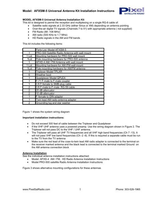
Model: AFXSM-5 Universal Antenna Kit Installation Instructions
Model: AFXSM-5 Universal Antenna Kit Installation Instructions
Model: AFXSM-5 Universal Antenna Kit Installation Instructions

Create successful ePaper yourself
Turn your PDF publications into a flip-book with our unique Google optimized e-Paper software.
<strong>Model</strong>: <strong>AFXSM</strong>-5 <strong>Universal</strong> <strong>Antenna</strong> <strong>Kit</strong> <strong>Installation</strong> <strong>Instructions</strong><br />
MODEL <strong>AFXSM</strong>-5 <strong>Universal</strong> <strong>Antenna</strong> <strong>Installation</strong> <strong>Kit</strong><br />
This kit is designed to permit the reception and multiplexing on a single RG-6 cable of:<br />
• Satellite radio signals at 2.33 GHz (either Sirius or XM) depending on antenna pointing<br />
• Over-the-air digital TV signals (Channels 7 to 51) with appropriate antenna ( not supplied)<br />
• FM Radio (88 -108 MHz)<br />
• AM radio (500 KHz to 1.7 MHz)<br />
• HD Radio signals in the AM and FM bands<br />
This kit includes the following items:<br />
Parts List: <strong>Model</strong> <strong>AFXSM</strong>-5<br />
1 PRO-500 Satellite Radio <strong>Antenna</strong> with wall mount<br />
1 Lot Mounting hardware for PRO-500 wall mount<br />
1Lot Pole mounting hardware for PRO-500 antenna<br />
1 AFHD-4 AM / FM <strong>Antenna</strong> with wall mount<br />
1 Lot Mounting hardware for AM /FM wall mount<br />
1Lot Pole mounting hardware for AM/FM antenna<br />
1 Triplexer <strong>Model</strong> TPLXR<br />
6 Weather boot<br />
1 Quadplexer <strong>Model</strong> QPLEX<br />
1 F-71 F-male to F-male coupler<br />
1 3 ft F-female to SMB-plug cable<br />
2 3 ft F-male to F-male RG-59 cable<br />
2 20 dB attenuator<br />
2 10 dB attenuator<br />
1 F-female to DIN adapter<br />
1 Twin lead AM radio antenna adapter<br />
2 Grounding lug and star washer<br />
Figure 1 shows the system wiring diagram<br />
Important installation instructions:<br />
• Do not exceed 300 feet of cable between the Triplexer and Quadplexer<br />
• If the VHF UHF antenna uses a powered preamp. Use the wiring diagram shown in Figure 2. The<br />
Triplexer will not pass DC to the VHF / UHF antenna.<br />
• The Triplexer will pass all UHF TV frequencies and all VHF high band frequencies (Ch 7 -13). It<br />
will not pass VHF low band frequencies (Ch -2 -6). If this is required a separate cable must be run<br />
to the TV from the TV antenna<br />
• Make sure the red lead of the coax-to-twin lead AM radio adapter is connected to the terminal on<br />
the receiver marked antenna and the black lead is connected to the terminal marked Ground on<br />
the AM antenna connection block<br />
<strong>Antenna</strong> <strong>Installation</strong><br />
See the individual antenna installation instructions attached:<br />
• <strong>Model</strong>: AFHD-4 AM / FM, HD Radio <strong>Antenna</strong> <strong>Installation</strong> <strong>Instructions</strong><br />
• <strong>Model</strong> PRO-500 satellite Radio <strong>Antenna</strong> <strong>Installation</strong> <strong>Instructions</strong><br />
Figure 3 shows alternative mounting configurations for these antennas<br />
www.PixelSatRadio.com 1 Phone: 303-526-1965
<strong>Model</strong>: <strong>AFXSM</strong>-5 <strong>Universal</strong> <strong>Antenna</strong> <strong>Kit</strong> <strong>Installation</strong> <strong>Instructions</strong><br />
www.PixelSatRadio.com 2 Phone: 303-526-1965
<strong>Model</strong>: <strong>AFXSM</strong>-5 <strong>Universal</strong> <strong>Antenna</strong> <strong>Kit</strong> <strong>Installation</strong> <strong>Instructions</strong><br />
www.PixelSatRadio.com 3 Phone: 303-526-1965
<strong>Model</strong>: <strong>AFXSM</strong>-5 <strong>Universal</strong> <strong>Antenna</strong> <strong>Kit</strong> <strong>Installation</strong> <strong>Instructions</strong><br />
www.PixelSatRadio.com 4 Phone: 303-526-1965
<strong>Model</strong>: <strong>AFXSM</strong>-5 <strong>Universal</strong> <strong>Antenna</strong> <strong>Kit</strong> <strong>Installation</strong> <strong>Instructions</strong><br />
Warranty<br />
Pixel Technologies warrants its products against defects in material or workmanship for a period of 12 months from<br />
the date of retail sale unless otherwise contracted.<br />
Defective products will be repaired or replaced at the sole discretion of Pixel Technologies, Inc.<br />
Shipping Your Product for Warranty Repair<br />
• When shipping your product you must include the following:<br />
• A copy of the receipt, invoice, or other proof of purchase.<br />
• A description of the problem<br />
• Include all original components that came with the unit. Missing components will not be replaced.<br />
• Include return name, physical address, & telephone number/email address and RMA number.<br />
(An RMA number can be obtained by calling Pixel Technologies at (303) 526-1965)<br />
• Please ship product by traceable means (such as UPS, FedEx, etc)<br />
Return Material Authorization (RMA)<br />
You must email or call us and obtain an RMA number before returning any product and be sure to write it clearly on<br />
the outside of the package. We reserve the right to refuse any products returned to us without a return authorization<br />
number clearly written on the outside of the return package. All returns or exchanges MUST be postmarked within 3<br />
business days after an RMA number is issued. Please keep products and packaging in like-new condition when<br />
returning for a refund to avoid fees for damaged/missing items. Packaging may be opened, but ALL items must be<br />
present including the packaging itself and literature. Items that have been physically damaged and show clear signs<br />
of wear also cannot be returned.<br />
Damaged, Missing, Delayed or Wrong Items Shipped<br />
Pixel Technologies is not responsible for items that may be damaged, lost, or missing by the shipping company, or<br />
"carrier" (UPS, DHL, USPS, etc.). All products and packaging should be carefully inspected upon receipt. Any and all<br />
claims regarding wrong item shipped, missing items, or items damaged in shipping must be made to us by email or<br />
phone within 7 (seven) calendar days of your order being marked delivered to you by the carrier; after that we can<br />
no longer file any claims. The purchaser should alert the carrier and Pixel Technologies that a claim needs to be filed<br />
for that shipment. Once the claim is approved, we will re-ship your item at no additional charge.<br />
If we shipped you the wrong item, we will ship out the correct item to you at no additional charge. We will ask that<br />
you return the incorrect item to us. An RMA number will be issued and you will be fairly compensated for your return<br />
shipping expenses. We reserve the right to choose a shipping method for your replacement, normally matching the<br />
same in-transit time as your original shipment.<br />
If an item is missing, we will review the order, checking correct package weight, etc.. If we determine that the item<br />
was in fact omitted through our error, we will ship the item out at no additional charge to you. Shipping method will be<br />
equal in speed to the original shipping method at time of order (Air or Express service may not apply to shipments<br />
going to Hawaii, Alaska, or Canada).<br />
If a piece is missing from a kit (for example, a cable) we will ship the missing piece via the carrier and shipping<br />
method of our choice.<br />
We will be happy to help you with the details of packaging and shipping your merchandise for credit or exchange if<br />
defective. Some limitations and restrictions apply. Replacements for defective items are usually shipped within 1-3<br />
business days (via ground) after receipt of the defective item.<br />
We strive to ship products out as soon as possible. Once items are shipped, Pixel Technologies has no control<br />
over the timeliness of the shipments and cannot be held responsible for any delays caused by the carrier.<br />
If necessary, Pixel Technologies will aid in the filing of an appropriate claim with the carrier in the event of<br />
package loss or damage. We cannot refund shipping charges regardless of reason for delayed shipments.<br />
www.PixelSatRadio.com 5 Phone: 303-526-1965
<strong>Model</strong>: AFHD-4 AM / FM HD Radio <strong>Antenna</strong> <strong>Installation</strong> <strong>Instructions</strong><br />
This kit includes the following items required to install the AFHD-4 AM / FM antenna<br />
Included items in the kit<br />
QTY Description<br />
1 AM / FM antenna<br />
1 L-mounting bracket<br />
1 Weather boot<br />
2 20 dB attenuator<br />
2 10 dB attenuator<br />
2 3 ft RG-6 cables<br />
2 U bolts with washers and nuts<br />
2 Pole mount saddle brackets<br />
4 Mounting screws with plastic inserts<br />
1 F-female to twin-lead adaptor<br />
1 Push-on F-female to DIN adapter<br />
<strong>Antenna</strong> Location<br />
For optimum results the antenna should be mounted outdoors as high above ground level and as far away as possible from any AM<br />
interference sources (see Table 1). It can also be mounted in an attic, but reception will depend on the roofing material and the<br />
insulation and siding materials. Thermal insulation that uses aluminum foil backing or metal roofing/siding material will shield the<br />
antenna from achieving good reception. Most stone and stucco siding has wire mesh reinforcement that will also block signal reception<br />
indoors. Before finalizing the mounting location it is recommended to experiment with a few different temporary locations. AM<br />
and FM reception can vary greatly as function of the antenna’s location.<br />
Cable length, Type and Routing<br />
Always use good quality RG-6 cable and do not run the cable more than 300 ft. (The shorter the better for best FM<br />
reception). (RG-6 cable has a loss of about 2.8 dB / 100 ft at the high end of the FM band (108 MHz)). For runs longer<br />
than 300 ft, a special wide-band line-amplifier is available to amplify the signal.<br />
For AM reception, RG-6 cable loss is not an issue (only 0.33 dB per 100 ft at 1.7 MHz) but for best rejection of local AM<br />
interference, Quad-shielded RG-6 should be considered. In addition, do not run the cable in parallel with cat 5 cables<br />
carrying digital signals or in parallel with AC power lines.<br />
<strong>Antenna</strong> Mounting<br />
The antenna L-bracket (Figure 1) should be first mounted in place to either a wall, chimney or a pole (not larger than 2<br />
inches in diameter) with the supplied hardware as shown in Figures 2 and 3. The antenna should be as high above<br />
ground level as practical and as far away as possible from local AM interference sources and any structure ( including<br />
aluminum siding) that could block reception.<br />
After mounting the L-bracket, screw the antenna rod into its base and tighten with a wrench.<br />
Use the included weather boot with the lead-in RG-6 cable or other weather proofing means to seal the outdoor F-<br />
connector from moisture ingress.<br />
Figure 1: L-Bracket Figure 2: Pole Mount Figure 3: Wall Mount<br />
www.PixelSatRadio.com 1 Phone: 303-526-1965
<strong>Model</strong>: AFHD-4 AM / FM HD Radio <strong>Antenna</strong> <strong>Installation</strong> <strong>Instructions</strong><br />
Wiring Diagram<br />
Wire the components to the Triplexer and Quadplexer as shown in Figure 1 of the <strong>Model</strong> <strong>AFXSM</strong>-5 <strong>Universal</strong> <strong>Antenna</strong> <strong>Kit</strong><br />
instruction sheet. Make sure the black wire from the coax- to- twin lead adapter is connected to the ground input of<br />
receiver’s AM antenna terminals.<br />
Attenuator Selection<br />
Occasionally nearby high-power transmitters (TV, AM or FM) can overload your receiver’s front-end causing crossmodulation<br />
distortion, audio distortion or noise. Use the supplied coaxial 10 dB (FAM-10) and 20 dB attenuators (FAM-<br />
20) on the outputs of the AM /FM band splitter to determine the best amount of attenuation that provides optimum<br />
reception.<br />
To do this, first tune the radio manually across the entire AM band one step at a time (do not use the channel scan or<br />
search function of the receiver) and note the station frequencies that you are receiving well. Repeat this with first a 10 dB<br />
and then a 20 dB attenuator to determine if the attenuators help or hurt overall reception. The attenuators can be<br />
combined to achieve different amounts of attenuation. In most cases no attenuation is required and the best reception is<br />
achieved. Once the reception for the AM band is optimized, repeat these steps for the FM band to determine the best<br />
attenuator setting. These are standard cable-TV type attenuators that can be obtained from Pixel and many other sources<br />
if additional attenuation is required.<br />
AM Interference:<br />
Unfortunately in this age of digital entertainment, AM radio has become the “weak sister” of features included in most<br />
entertainment systems. Most receiver manufacturers are spending the minimum possible amount on their AM tuning<br />
sections and the number of household source of AM radio interference has increased exponentially (see Table 1 below).<br />
Fortunately the emergence of Hybrid Digital (HD) AM radio technology is helping to cure some of these problems but the<br />
best strategy for good AM reception is to first eliminate as many of the interference sources as is practical and then<br />
locate the receiving antenna as far away as possible from the remaining interference sources. Using high quality wellshielded,<br />
Quad RG-6 lead-in wire from the antenna to the receiver will help reduce interference and optimize reception.<br />
Table 1. Typical sources of AM Radio Interference<br />
Dimmer switch<br />
Neighbor’s dimmer switch<br />
Fluorescent light<br />
Computer<br />
Touch lamp (even when turned off)<br />
Automatic on/off night lights.<br />
Automatic outdoor yard lights<br />
Electronic bug and pest controllers<br />
Light bulb that is about to burn out<br />
Faulty electrical switch<br />
Nearby television, plasma or LCD display<br />
Neighbor using fluorescent lights<br />
Christmas tree lights & other blinking bulbs<br />
Neighbor’s dimmer switch (apt. complex)<br />
Cell phone chargers<br />
Dirty insulators on nearby power pole<br />
Electric blanket<br />
120V AC smoke detectors (battery operated OK)<br />
Ionic Breeze or other electrostatic air purifier<br />
Ultrasonic motion detectors<br />
Appliances with motors<br />
Lap top computer power supply<br />
Almost any wall mounted power supply that uses a "switching design"<br />
Computer network "Cat 5" wiring<br />
www.PixelSatRadio.com 2 Phone: 303-526-1965
<strong>Model</strong>: AFHD-4 AM / FM HD Radio <strong>Antenna</strong> <strong>Installation</strong> <strong>Instructions</strong><br />
Specifications:<br />
<strong>Antenna</strong> length: 48 inches<br />
Frequency of operation:<br />
AM Band 500 KHz to 1750 KHz<br />
FM Band 88MHz -108 MHz<br />
Ground plane required: None<br />
AM capture length: 300 inches<br />
AM / FM Band Separator Performance:<br />
FM rejection in AM band: > 50 dB<br />
AM rejection in FM band: > 60 dB<br />
AM/FM Pass-band loss: < 1dB<br />
AM load impedance: 300 ohms<br />
FM load impedance: 75 ohms<br />
<strong>Antenna</strong> Beam width: Omni-directional<br />
Reception Performance:<br />
These results will vary as function of the antenna’s height above ground, the power of the transmitting station, the<br />
transmitter’s antenna beam pattern, the local terrain and the quality of the receiver utilized. Table 2 shows actual<br />
reception test results for the antenna mounted 20 feet above ground over flat terrain, using a Sangean <strong>Model</strong> HDT-1X as<br />
the receiver with 200 ft of cable between the antenna and receiver.<br />
Table 2. Reception Capability<br />
Receiver Mode<br />
FM Stereo<br />
FM HD<br />
AM (Mono)<br />
AM HD<br />
Reliable Good Quality<br />
Daytime Reception<br />
80 Miles<br />
50 Miles<br />
90 Miles<br />
50 Miles<br />
Test Conditions:<br />
Receiver:<br />
Sangean HDT-1X<br />
Cable Length (antenna to receiver): 200 feet RG-6 cable<br />
<strong>Antenna</strong> height above ground: 20 feet<br />
Terrain: Flat<br />
www.PixelSatRadio.com 3 Phone: 303-526-1965
<strong>Model</strong>: PRO-500 Satellite Radio <strong>Antenna</strong> <strong>Installation</strong> <strong>Instructions</strong><br />
This antenna can be used for reception of XM or Sirius Satellite Radio (but not both simultaneously). Its internal<br />
voltage regulator makes it compatible with all generations and models of XM and Sirius radios.<br />
IMPORTANT SAFETY INSTRUCTIONS<br />
• Read and Retain <strong>Instructions</strong> – Read all <strong>Instructions</strong> before operating equipment and save for future reference.<br />
• Outdoor <strong>Antenna</strong> Grounding – The antenna and coaxial cable connecting to the unit should be properly<br />
grounded to provide protection against voltage surges and built-up static charges. Article 810 of the National<br />
Electrical Code (NEC), ANSI/NFPA 70, provides information with regard to proper grounding of the mast and<br />
supporting structure, grounding of the lead-in wire to an antenna discharge unit, size of grounding conductors,<br />
location of antenna-discharge unit, connection to grounding electrodes, and requirements for the grounding<br />
electrode.<br />
• Power Lines – An outside antenna system should not be located in the vicinity of overhead power lines or<br />
electric light or power circuits, or where they can fall into such power lines or circuits. When installing an outside<br />
antenna system, extreme care should be taken to keep from touching such power lines or circuits, as contact<br />
with them might be fatal.<br />
The required components include the following:<br />
QTY Description<br />
1 <strong>Antenna</strong> Panel & Wall mount<br />
1 U-bolt<br />
1 Saddle bracket<br />
1 F-female to SMB-plug adapter cable, 3’<br />
1 Rubber weather boot<br />
1 lot Mounting and assembly hardware<br />
1 Grounding lug and star washer<br />
Figure 1: Included Items for PRO- 500 <strong>Antenna</strong><br />
Wall Mounting and <strong>Antenna</strong> Alignment<br />
Attach the wall mount assembly to any vertical or horizontal flat surface. Use the supplied screws to secure the<br />
mount in the position desired (use of the included anchors requires 5/16” holes).<br />
• Connect an RG-6 coaxial cable (not supplied) with male F-connectors to the antenna and to the Sat Radio input<br />
of the Triplexer ( the sum of all the cable lengths from the antenna to the Triplexer and from the Triplexer to the<br />
Quadplexer and from the Quadplexer to the radio should not exceed 300 feet. Using the supplied 3 ft F-Female<br />
to SMB adapter cable, connect the Quadplexer’s Sat Radio output to the satellite radio’s antenna input. For<br />
cable runs exceeding 300 feet, special line amplifiers are available to increase the signal strength.<br />
• Adjust the azimuth and elevation pointing of the antenna for best reception using the antenna signal strength<br />
menu in the radio. The antenna has a beam width of ± 25º, which is narrower than standard consumer- quality<br />
home-kit antennas, but provides higher gain and rejection to multi-path interference.<br />
Appendix 1 lists exact magnetic azimuth bearings and elevation pointing angles for many major cities<br />
throughout the US and Canada.<br />
• Tighten all hardware and seal the outdoor connectors using the included weather boots or other means to<br />
prevent moisture ingress. Provide a strain relief for the cable.<br />
www.PixelSatRadio.com Phone: 303-526-1965<br />
1
<strong>Model</strong>: PRO-500 Satellite Radio <strong>Antenna</strong> <strong>Installation</strong> <strong>Instructions</strong><br />
• Tighten all hardware and seal the outdoor connectors using the included weather boot or other means to prevent<br />
moisture ingress. Provide a strain relief for the cable.<br />
Pole Mounting<br />
• Attach the pole mount bracket to any pole (not larger than 2 inches in diameter) using the U-bolt and saddle as<br />
shown in Figure 3.<br />
Saddle<br />
bracket<br />
U-bolt<br />
Nuts and washers<br />
Pole not larger<br />
than 2 inches in<br />
diameter<br />
Wall mount bracket<br />
Figure 3: Pole Mount U-bolt & saddle<br />
• Tighten all hardware and seal the outdoor connectors using the included weather boots or other means to<br />
prevent moisture ingress. Provide a strain relief for the cable.<br />
XM Reception<br />
XM has two satellites located at fixed orbital positions in the southern sky (at 115° W longitude and 85º W longitude).<br />
These satellites each carry all of the XM channels, so it is only required to have an un-obscured line-of-sight to one of<br />
these orbital locations. To initially set up the antenna, orient it approximately due south at an up elevation angle of<br />
approximately 45º. Use this as starting spot and peak the signal reception for maximum signal reception on one of the<br />
XM satellites using the antenna alignment menu in the radio.<br />
Sirius Reception<br />
Sirius has three satellites in elliptical orbit that are constantly moving over the earth. These orbits are arranged so that<br />
two satellites are always in view at any point in time at relatively high elevation angles (from + 45° to almost 90°) in<br />
the sky. Figure 4 shows relative azimuth pointing guidelines for reception in different regions of the US, and Figure 5<br />
shows them for Canada.<br />
Because the satellites’ positions are constantly changing, signal strength will vary somewhat at different times of the<br />
day. The “sweet spot” for optimum Sirius antenna pointing is just over the eastern border of North Dakota. Figures 4<br />
www.PixelSatRadio.com 2<br />
Phone: 303-526-1965
<strong>Model</strong>: PRO-500 Satellite Radio <strong>Antenna</strong> <strong>Installation</strong> <strong>Instructions</strong><br />
and 5 show approximate pointing guidelines for five regions of the US and three regions of Canada. These guidelines<br />
should get you close to optimum. The radio’s antenna / signal menu should be used to make fine adjustments.<br />
Appendix 1 shows the exact magnetic azimuth and elevation pointing for major cities in the US and Canada.<br />
However, exact precision pointing is rarely necessary.<br />
Figure 4: SIRIUS <strong>Antenna</strong> Pointing Guidelines, United States<br />
AREA<br />
AREA 1<br />
AREA 2<br />
AREA 3<br />
AREA 4<br />
AREA 5<br />
ANTENNA AIMING DIRECTION UNITED STATES<br />
Aim the antenna EAST or NORTHEAST<br />
Aim the antenna NORTH or NORTHEAST<br />
Aim the antenna NORTH or NORTHWEST<br />
Aim the antenna WEST or NORTHWEST<br />
Aim the antenna STRAIGHT UP at the sky<br />
Figure 5 : SIRIUS <strong>Antenna</strong> Pointing Guidelines, Canada<br />
AREA<br />
AREA 1<br />
AREA 2<br />
AREA 3<br />
ANTENNA AIMING DIRECTION CANADA<br />
Aim the antenna EAST or SOUTHEAST<br />
Aim the antenna SOUTH or STRAIGHT UP at the sky<br />
Aim the antenna WEST or SOUTHWEST<br />
www.PixelSatRadio.com Phone: 303-526-1965<br />
3
<strong>Model</strong>: PRO-500 Satellite Radio <strong>Antenna</strong> <strong>Installation</strong> <strong>Instructions</strong><br />
<strong>Installation</strong> Notes<br />
• Mount the antenna outdoors with the supplied wall mount or pole mount bracket. Operation indoors or<br />
behind windows is not recommended. Window panes can have tinted coatings which can attenuate the<br />
signal. The attenuation of these coatings can vary greatly as the temperature changes.<br />
• (XM <strong>Installation</strong>) Use the menus in the radio to peak the satellite signal reception on one of the satellites. It is not<br />
necessary to position the antenna for simultaneous reception of multiple satellites.<br />
• The antenna’s internal low noise amplifier is designed to compensate for the loss of up to 300 feet of RG-6<br />
cable. For longer cable runs use an in-line amplifier (Pixel <strong>Model</strong> SBA-1) to boost the signal at its input to the<br />
Triplexer.<br />
• Although this antenna can receive signals from terrestrial repeaters, it is recommended to always use the<br />
satellite signals for primary reception at fixed sites. The satellite signals are much more stable and are not<br />
affected by many uncontrolled variables that can greatly impact signal quality from repeaters over time.<br />
• Seal all outdoor coax connector fittings with the weather boot (supplied), sealant or weatherized tape<br />
to eliminate moisture ingress.<br />
Troubleshooting<br />
Problem: No signal reception and the following messages may be displayed on the radio:<br />
<strong>Antenna</strong>:<br />
This error signal indicates that the antenna is not properly connected.<br />
• Ensure there are no “shorts” or discontinuities in the cables and that all connections are tight. The easiest<br />
way to do this is as follows:<br />
• With the radio turned on and all antenna cables connected at the radio, check the DC voltage at the antenna<br />
end of the cable. It should be between 4 VDC and 7 VDC.<br />
No Signal:<br />
This error signal indicates that the antenna is connected properly but that the signal is too weak for reception.<br />
• Ensure the sum total of all cables between the antenna and radio does not exceed 300 Feet and it is RG-6<br />
cable.<br />
• Ensure the antenna is properly aimed.<br />
www.PixelSatRadio.com Phone: 303-526-1965<br />
4
<strong>Model</strong>: PRO-500 Satellite Radio <strong>Antenna</strong> <strong>Installation</strong> <strong>Instructions</strong><br />
Appendix 1<br />
The following chart shows the optimum azimuth bearing and elevation pointing angles for locations throughout the US<br />
and Canada. The azimuth has been magnetically corrected.<br />
Warning: Although in many locations it may be possible to receive signals from terrestrial repeaters, it is not<br />
recommended to use these signals at fixed locations. Repeater signal strength can vary greatly from day to<br />
day as function of many uncontrolled variables.<br />
Sirius XM Sat 1 (West 85°) XM Sat 2 (West 115 °)<br />
City St Azimuth° Elevation° Azimuth° Elevation° Azimuth° Elevation°<br />
Birmingham AL 324.1 71.5 179.1 49.1 223.5 39.8<br />
Dothan AL 325.5 68.4 182.1 51.8 227.5 40.9<br />
Little Rock AR 337.9 75.9 166.6 47.0 212.1 41.6<br />
Phoenix AZ 40.7 66.7 128.0 40.5 173.0 49.1<br />
Fillmore CA 50.8 60.7 119.2 35.5 160.0 47.9<br />
Los Angeles CA 49.0 61.1 119.8 36.3 161.2 48.4<br />
San Diego CA 45.7 61.4 120.6 38.0 163.4 50.0<br />
San Francisco CA 58.5 58.3 116.4 30.6 153.8 43.5<br />
Denver CO 43.8 77.6 142.4 37.9 184.4 40.8<br />
Washington DC 300.0 65.7 202.5 42.1 239.2 29.4<br />
Ft Myers FL 326.3 61.8 190.9 57.2 237.1 42.0<br />
Jacksonville FL 320.9 64.9 191.3 52.7 234.8 39.2<br />
Key West FL 328.5 59.9 191.3 59.6 238.9 43.4<br />
Miami FL 325.2 59.9 195.4 57.9 240.5 41.4<br />
Tampa FL 325.7 63.5 189.3 55.6 235.1 41.5<br />
Atlanta GA 318.6 69.9 185.0 48.8 228.0 38.1<br />
Savannah GA 317.3 65.8 192.8 50.6 234.9 37.4<br />
Pocatello ID 355.3 70.9 131.0 31.6 169.6 38.1<br />
Chicago IL 298.0 78.6 179.4 39.2 218.5 32.6<br />
Dodge City KS 16.3 79.2 151.1 41.6 194.9 41.7<br />
Kansas City KS 341.5 81.6 162.9 41.5 205.2 38.3<br />
Louisville KY 309.3 74.5 182.7 43.5 223.4 35.0<br />
New Orleans LA 337.0 69.8 170.1 52.9 219.5 45.0<br />
Boston MA 293.3 60.0 214.5 36.9 247.9 23.2<br />
Germantown MD 299.7 66.1 202.0 41.8 238.7 29.4<br />
Caribou ME 287.4 56.8 220.2 31.3 252.0 19.0<br />
Portland ME 291.3 59.3 216.1 35.3 248.9 21.8<br />
Meridian MN 300.8 85.8 166.9 36.1 205.8 32.8<br />
Minneapolis MN 285.8 86.0 167.7 35.1 206.0 31.8<br />
St Louis MO 319.7 78.7 172.6 42.8 214.4 36.9<br />
Billings MT 76.2 75.9 137.9 30.4 175.6 34.5<br />
Kalispell MT 80.8 68.9 129.1 25.8 164.8 32.0<br />
Winston-Salem NC 308.2 67.7 195.2 45.8 234.6 33.6<br />
Minot ND 106.5 83.7 151.7 30.0 188.7 30.6<br />
North Platte NE 33.8 82.4 150.8 37.8 192.0 38.2<br />
Omaha NE 349.9 84.4 160.7 38.9 201.7 36.6<br />
Cherry Hill NJ 297.6 63.9 206.7 40.5 242.3 27.4<br />
Albuquerque NM 33.1 72.6 137.5 41.8 183.0 46.4<br />
Shiprock NM 41.9 72.0 134.8 39.3 178.3 44.9<br />
Elco NV 61.0 66.7 125.7 31.9 164.4 40.5<br />
Las Vegas NV 49.9 65.4 124.9 36.3 166.5 46.0<br />
Reno NV 60.2 61.7 120.0 30.8 157.8 41.8<br />
Brooklyn NY 295.9 62.8 208.9 39.5 243.7 26.2<br />
Albany NY 292.2 63.1 209.5 37.3 243.8 24.6<br />
www.PixelSatRadio.com Phone: 303-526-1965<br />
5
<strong>Model</strong>: PRO-500 Satellite Radio <strong>Antenna</strong> <strong>Installation</strong> <strong>Instructions</strong><br />
Sirius XM Sat 1 (West 85°) XM Sat 2 (West 115 °)<br />
City St Azimuth° Elevation° Azimuth° Elevation° Azimuth° Elevation°<br />
Buffalo NY 290.5 69.1 199.1 37.8 235.1 27.3<br />
New York NY 295.9 63.0 208.8 39.4 243.7 26.2<br />
Cleveland OH 294.6 71.8 192.6 39.7 230.1 30.0<br />
Tulsa OK 352.6 78.4 158.8 44.6 203.8 41.9<br />
Burns OR 67.9 63.4 121.9 27.9 158.4 37.3<br />
Eugene OR 69.0 58.9 117.1 25.3 152.1 36.2<br />
Pendleton OR 72.4 63.9 122.6 26.2 158.3 34.8<br />
Philadelphia PA 297.5 64.1 206.4 40.6 242.0 27.5<br />
Newport RI 294.7 60.1 214.0 37.9 247.7 24.0<br />
Columbia SC 313.4 67.1 193.1 48.3 234.0 35.8<br />
Pierre SD 59.5 85.1 152.7 34.4 191.8 34.6<br />
Nashville TN 317.6 73.8 179.8 45.9 222.2 37.4<br />
Dallas TX 356.4 74.5 155.6 48.1 204.1 45.7<br />
Houston TX 352.0 70.9 157.3 52.0 209.1 48.1<br />
Lubbock TX 15.8 74.1 145.6 45.5 193.3 46.8<br />
San Antonio TX 1.1 70.5 150.0 51.2 202.8 50.0<br />
Salt Lake City UT 58.4 70.9 131.3 33.9 171.1 40.5<br />
Milford UT 52.6 68.7 128.8 35.6 169.9 43.4<br />
Norfolk VA 304.1 64.1 204.1 44.3 241.2 30.5<br />
Burlington VT 288.9 62.7 210.8 35.1 244.5 22.9<br />
Seattle WA 75.0 59.8 118.3 22.8 152.5 32.3<br />
Green Bay WI 283.3 79.9 179.3 36.2 217.1 30.3<br />
Milwaukee WI 291.9 79.3 179.1 37.9 217.6 31.6<br />
Charleston WV 303.8 70.4 192.2 43.3 231.2 32.6<br />
Casper WY 61.3 77.9 141.0 34.1 180.7 37.5<br />
Canada Sirius XM Rock (East 85°) XM Roll (West 115 °<br />
City Pr Azimuth Elevation Azimuth Elevation Azimuth Elevation<br />
Vancouver BC 78.4 58.7 115.9 22.9 151.3 33.0<br />
Prince Rupert BC 81.4 49.7 108.0 15.9 140.6 26.5<br />
Calgary AB 89.7 68.6 128.6 25.5 165.3 31.5<br />
Edmonton AB 129.7 68.3 162.3 23.5 198.2 28.8<br />
Saskatoon SK 109.0 76.0 141.4 27.0 178.6 29.9<br />
Toronto ON 287.9 69.8 198.6 39.3 236.5 28.4<br />
Ottawa ON 282.6 65.6 204.0 36.9 240.1 25.1<br />
Montreal QB 286.3 63.2 210.9 36.4 246.1 23.8<br />
St Johns QB 286.8 62.8 211.5 36.6 246.6 23.7<br />
Halifax NS 290.7 51.7 227.8 34.3 259.4 18.1<br />
Saint John's NF 288.2 39.4 240.4 27.1 268.6 9.7<br />
Brandon MT 131.5 83.9 154.3 31.1 193.0 31.1<br />
Sault Sainte<br />
Marie ON 274.9 75.7 188.3 36.5 226.7 28.7<br />
Thunder Bay ON 255.0 80.9 177.8 34.3 216.3 29.1<br />
Whitehorse YT 84.2 42.8 102.7 9.8 133.9 19.2<br />
Winnipeg MA 165.3 85.4 159.3 31.7 197.9 30.4<br />
Yellowknife NT 110.9 61.7 127.2 15.3 160.3 19.3<br />
www.PixelSatRadio.com Phone: 303-526-1965<br />
6