On Limitation of the Current of Low-Energy, High-Current Electron ...
On Limitation of the Current of Low-Energy, High-Current Electron ...
On Limitation of the Current of Low-Energy, High-Current Electron ...

Create successful ePaper yourself
Turn your PDF publications into a flip-book with our unique Google optimized e-Paper software.
Poster Session<br />
<strong>On</strong> <strong>Limitation</strong> <strong>of</strong> <strong>the</strong> <strong>Current</strong> <strong>of</strong> <strong>Low</strong>-<strong>Energy</strong>, <strong>High</strong>-<strong>Current</strong> <strong>Electron</strong><br />
Beam Formed in Plasma-Filled Diode 1<br />
G.E. Ozur<br />
Institute <strong>of</strong> <strong>High</strong> <strong>Current</strong> <strong>Electron</strong>ics SB RAS, 2/3, Akademicheskii ave., Tomsk, 634055, Russia<br />
Phone: 8(3822) 49-20-52, Fax: 8(3822) 49-24-10, E-mail: ozur@Lve.hcei.tsc.ru<br />
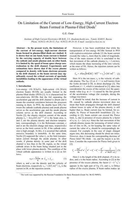
Abstract – In <strong>the</strong> present work, <strong>the</strong> limitations <strong>of</strong><br />
<strong>the</strong> current <strong>of</strong> low-energy, high-current electron<br />
beam formed in plasma-filled diode are studied. It<br />
is shown that on one hand, beam current is limited<br />
by <strong>the</strong> carrying capacity <strong>of</strong> double layer between<br />
<strong>the</strong> cathode and anode plasmas and, on o<strong>the</strong>r hand,<br />
it is limited by <strong>the</strong> speed <strong>of</strong> beam space charge neutralization<br />
in <strong>the</strong> drift channel. Experiments and<br />
estimations have shown that if <strong>the</strong> excess plasma<br />
compared in density with beam electrons presents<br />
in <strong>the</strong> drift channel, so <strong>the</strong> beam current may significantly<br />
exceed <strong>the</strong> critical currents <strong>of</strong> aperiodic<br />
instabilities leading to <strong>the</strong> appearance <strong>of</strong> <strong>the</strong> virtual<br />
cathode.<br />
1. Introduction<br />
<strong>Low</strong>-energy (10–30 keV), high-current (10–20 kA)<br />
electron beams HCEBs are usually formed in <strong>the</strong><br />
plasma-filled diodes (PFD) [1]. It is characterized for<br />
non-relativistic HCEBs that <strong>the</strong> foil separating <strong>the</strong><br />
acceleration gap and <strong>the</strong> drift channel is absent and it<br />
means <strong>the</strong> essential correlation between <strong>the</strong> processes<br />
running in <strong>the</strong>m. In PFD, <strong>the</strong> double layer (DL) between<br />
<strong>the</strong> cathode (cathode plasma) and anode plasma<br />
serves as <strong>the</strong> acceleration gap and <strong>the</strong> anode plasma<br />
column serves as <strong>the</strong> drift channel. According to<br />
Nezlin [2], <strong>the</strong> chaotic electron current <strong>of</strong> <strong>the</strong> anode<br />
plasma I еа = Sen a (2kT e /m) 1/2/4 (S is <strong>the</strong> beam area, n a<br />
and T e are <strong>the</strong> plasma density and electron temperature,<br />
correspondingly, k is <strong>the</strong> Boltzmann constant, e<br />
and m are <strong>the</strong> electron charge and mass, respectively)<br />
serves as <strong>the</strong> limit current in DL if <strong>the</strong> cathode emission<br />
is high enough. At this, it is assumed that cathode<br />
emissive boundary is immobile. At <strong>the</strong> same time,<br />
Nezlin [2] supposed <strong>the</strong> value I еа as <strong>the</strong> limit transportation<br />
current through <strong>the</strong> anode plasma. In o<strong>the</strong>r<br />
words, if plasma density in some part <strong>of</strong> <strong>the</strong> drift<br />
channel is less than in <strong>the</strong> DL region, so <strong>the</strong> virtual<br />
cathode arises in <strong>the</strong> beam being situated just in <strong>the</strong><br />
place with lower plasma density. The condition <strong>of</strong> <strong>the</strong><br />
virtual cathode appearance is written in в [2] as follows:<br />
navea<br />
n<br />
bu<br />
> or I<br />
inj<br />
> I , (1)<br />
ea<br />
4<br />
where n b and u are <strong>the</strong> density and <strong>the</strong> velocity <strong>of</strong><br />
beam electrons, respectively v ea = (2kT e /m) 1/2 ; I inj is <strong>the</strong><br />
current in DL or <strong>the</strong> injection current.<br />
______________<br />
1 The work was supported by <strong>the</strong> Russian Foundation for Basic Research (Grant No. 06-02-96905).<br />
81<br />
However, it has been established that while <strong>the</strong><br />
transportation <strong>of</strong> low-energy HCEBs formed in PFD<br />
with explosive-emission cathode [1] <strong>the</strong> beam current<br />
exceeds <strong>the</strong> value I еа more than by order <strong>of</strong> magnitude.<br />
<strong>On</strong>e <strong>of</strong> <strong>the</strong> main reasons <strong>of</strong> this is concluded in <strong>the</strong><br />
fast movement <strong>of</strong> <strong>the</strong> cathode plasma (v p ≈ 2 cm/ms),<br />
which means <strong>the</strong> sharp increasing <strong>of</strong> <strong>the</strong> ions velocity<br />
at <strong>the</strong> enter <strong>of</strong> DL. Hence, <strong>the</strong> injection current can be<br />
written as follows:<br />
{ 0.4( 2kT<br />
/ M)<br />
} 1 /2<br />
+ v ( M / m) 1/ 2<br />
Iinj = ASena<br />
e<br />
p<br />
× . (2)<br />
Here М is <strong>the</strong> ion mass; v p is <strong>the</strong> velocity <strong>of</strong> cathode<br />
plasma. The Eq. (2) at А = 1 is well known from<br />
<strong>the</strong> works devoted to DL in direct discharge [3]. The<br />
coefficient А > 1, which is introduced in [1], takes into<br />
consideration <strong>the</strong> excess <strong>of</strong> <strong>the</strong> current over <strong>the</strong> quasisteady<br />
value (e.g. at A = 1) caused by <strong>the</strong> fast growth<br />
<strong>of</strong> <strong>the</strong> acceleration voltage (for example, during <strong>the</strong><br />
voltage rise-time).<br />
It should be noted, that <strong>the</strong> increase <strong>of</strong> current in<br />
DL caused by cathode plasma movement does not<br />
mean that beam propagates through <strong>the</strong> drift channel<br />
without losses in spite <strong>of</strong> <strong>the</strong> plasma density is still<br />
higher than n b . Beam current may be limited, for example,<br />
by Pierce <strong>of</strong> beam-drift instabilities [2]. According<br />
to [2], beam current can exceed <strong>the</strong> Pierce<br />
limit, I P , due to presence <strong>of</strong> excess plasma by a factor<br />
<strong>of</strong> n a /n b : I b = I P (n a /n b ). Since <strong>the</strong> fast movement <strong>of</strong> <strong>the</strong><br />
cathode plasma means <strong>the</strong> increasing <strong>of</strong> initial velocities<br />
<strong>of</strong> ions in DL, so for keeping <strong>the</strong> same value <strong>of</strong><br />
current <strong>the</strong> value <strong>of</strong> n a should be correspondingly decreased.<br />
For example in <strong>the</strong> case <strong>of</strong> single charged<br />
argon ions, this decreasing should be about ten times.<br />
However, does it mean <strong>the</strong> corresponding decrease <strong>of</strong><br />
Pierce limit We think – no, and <strong>the</strong> reason is as follows.<br />
Consider <strong>the</strong> expression for Pierce limit given in<br />
[2]:<br />
2 2<br />
ma 2 3<br />
⎛<br />
2 2 2 π 2 ⎞<br />
Ip = k u , ⎜k = ks + kr<br />
= +<br />
.<br />
2 2 ⎟ (3)<br />
4e ⎝<br />
L a ln( R/ a)<br />
⎠<br />
Here L is <strong>the</strong> length <strong>of</strong> <strong>the</strong> drift channel, R is its radius,<br />
and а is <strong>the</strong> beam radius. According to [2] at <strong>the</strong><br />
presence <strong>of</strong> <strong>the</strong> excess plasma, <strong>the</strong> factor (1 + k –2 r 2 )<br />
appears in <strong>the</strong> right part <strong>of</strong> Eq. (3), and r D is Debye<br />
radius <strong>of</strong> <strong>the</strong> excess plasma. If beam radius makes up<br />
−<br />
D
Intense <strong>Electron</strong> and Ion Beams<br />
several centimeters, so <strong>the</strong> second item in brackets<br />
becomes much higher than unit starting from<br />
n e = (n a – n b ) ≈ 108 cm –3 . Substituting this factor into<br />
Eq. (3) one can obtain<br />
2<br />
ma 3 −2<br />
I<br />
P<br />
≈ u rD<br />
.<br />
4e<br />
(4)<br />
Compare I P with I ea , one can obtain <strong>the</strong> following<br />
expression:<br />
I<br />
I<br />
⎛<br />
8⎜<br />
⎝<br />
u<br />
⎞<br />
⎟<br />
⎠<br />
P<br />
e<br />
≈<br />
⎜<br />
1/ 2<br />
ea [ 2kTe<br />
/ m] ⎟ n . (5)<br />
a<br />
It is evident from (5), that if <strong>the</strong> velocity <strong>of</strong> beam<br />
electrons in <strong>the</strong> drift channel is even if five times<br />
higher than <strong>the</strong> <strong>the</strong>rmal velocity <strong>of</strong> plasma electrons<br />
and n e ~ n a , <strong>the</strong> limitation <strong>of</strong> beam current by Pierce<br />
and/or beam-drift instability practically disappears.<br />
<strong>On</strong>e more important consequence follows from Exp.<br />
(5): for essential increasing <strong>of</strong> <strong>the</strong> Pierce limit, <strong>the</strong>re is<br />
need in <strong>the</strong> significant amount <strong>of</strong> <strong>the</strong> excess plasma as<br />
it is stated in [2]. Our result agrees with <strong>the</strong> results<br />
obtained by Zharinov with co-workers [4] in those<br />
respect that <strong>the</strong>ir calculations give <strong>the</strong> similar values<br />
<strong>of</strong> <strong>the</strong> excess plasma density (about 1012 cm –3 ) for<br />
removal <strong>of</strong> <strong>the</strong> Pierce limitation.<br />
Properly speaking, <strong>the</strong> statement <strong>of</strong> author [2]<br />
about <strong>the</strong> increase <strong>of</strong> beam current to <strong>the</strong> value <strong>of</strong><br />
I b = I P (n а /n b ) is based on <strong>the</strong> comparison <strong>of</strong> beam current<br />
obtained in experiment (4 A at 120 eV kinetic<br />
energy) with <strong>the</strong> calculated one (25 mA) for <strong>the</strong> case<br />
n e = 0. In fact in <strong>the</strong> experiment described in [2],<br />
I b = I P (n а /n b ), but simultaneously <strong>the</strong> beam current<br />
was close to I еа , e.g., to <strong>the</strong> current which must propagate<br />
through plasma. Thus, we have deal with simple<br />
coinciding. As we show above, beam current may<br />
significantly exceed Pierce limit with <strong>the</strong> presence <strong>of</strong><br />
comparatively small amount <strong>of</strong> <strong>the</strong> excess plasma. We<br />
observed this in our previous experiments [1], in<br />
which beam current exceeded <strong>the</strong> Pierce limit by 30–<br />
50 times while <strong>the</strong> relation n а /n b was about 10 only.<br />
Taking into account <strong>the</strong> finite value <strong>of</strong> guide magnetic<br />
field [5] may increase <strong>the</strong> Pierce limit by a factor <strong>of</strong><br />
2–3 only, so this cannot explain experimental data.<br />
Pay attention that according to Exp. (4) <strong>the</strong> Pierce<br />
limit (and beam current too) should not already depend<br />
on <strong>the</strong> length <strong>of</strong> drift channel if <strong>the</strong> excess<br />
plasma is available inside it. The same conclusion<br />
follows from Eq. (3) in <strong>the</strong> case <strong>of</strong> L >> a. However,<br />
<strong>the</strong> results <strong>of</strong> experiments [1] as well as experiments<br />
described below have shown that beam current decreases<br />
with <strong>the</strong> increasing <strong>of</strong> L. For example in [1]<br />
<strong>the</strong> increase <strong>of</strong> L from 27.5 cm to 57.5 cm results in<br />
decreasing <strong>the</strong> beam current amplitude from 23 kA to<br />
11 kA. Thus, <strong>the</strong>re is ano<strong>the</strong>r reason <strong>of</strong> HCEB limitation<br />
caused by <strong>the</strong> processes in <strong>the</strong> drift channel. The<br />
present work is devoted to <strong>the</strong> refinement <strong>of</strong> <strong>the</strong> reasons<br />
responsible to limitation <strong>of</strong> <strong>the</strong> HCEB current in<br />
PFD.<br />
3<br />
n<br />
82<br />
2. Experimental apparatus<br />
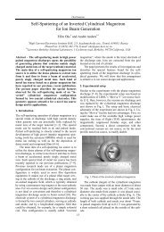
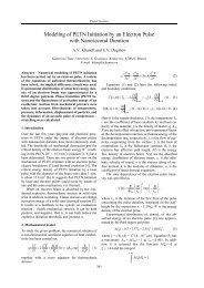
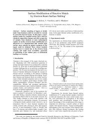
The block-diagram <strong>of</strong> experimental setup is given in<br />
Fig. 1. The body <strong>of</strong> electron gun made <strong>of</strong> stainless<br />
steel represents itself <strong>the</strong> tube <strong>of</strong> length 340 mm and<br />
inner diameter <strong>of</strong> 158 mm mounted to vacuum chamber<br />
<strong>of</strong> 400 mm in diameter. Thus, <strong>the</strong> drift tube was<br />
stepped in contrast to <strong>the</strong> case <strong>of</strong> [1], where <strong>the</strong> transportation<br />
was performed in <strong>the</strong> strait tube. Cathode<br />
diameter was 48 mm.<br />
Fig. 1. Experimental setup: 1 – explosive-emission cathode;<br />
2 – Penning discharge anode; 3 – collector; 4 – chamber; 5 –<br />
insulator; 6 – cathode plasma; 7 – anode plasma; 8 – solenoid;<br />
9 – Rogowsky coil<br />
Plasma anode was formed with <strong>the</strong> use <strong>of</strong> highcurrent<br />
(120–150 A) reflective (Penning) discharge in<br />
argon at <strong>the</strong> pressure p = 0.015–0.07 Pa. The residual<br />
gas pressure was 5 × 10 –3 Pa. The discharge was triggered<br />
by applying <strong>the</strong> positive pulse (5 kV) to <strong>the</strong> anode.<br />
The anode represents a stainless steel thin-wall<br />
ring <strong>of</strong> 69 mm in diameter and 20 mm in length.<br />
The external guide magnetic field <strong>of</strong> 2.5 kOe provided<br />
both reflective discharge operation and beam<br />
transport. The acceleration voltage pulse was monitored<br />
by resistive divider R1, R2. Cathode current was<br />
measured using Rogowsky coil 9, and beam current<br />
onto <strong>the</strong> collector was measured by low-inductance<br />
shunt Rsh. Signals were registered using 4-channel<br />
digital oscilloscope Tektronix TDS-2024 with bandwidth<br />
200 MHz.<br />
In experiments, <strong>the</strong> dependences <strong>of</strong> beam current<br />
and beam energy at <strong>the</strong> distance L g-c (Fig. 1) were<br />
studied. Working gas pressure and guide magnetic<br />
field strength was also varied. Beam energy was<br />
measured using calorimeter <strong>of</strong> 110 mm in diameter.<br />
3. Results and discussion<br />
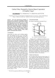
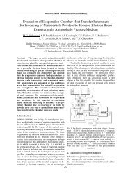
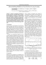
Typical waveforms obtained for different L g-c are presented<br />
in Fig. 2. It is evident that beam current amplitude<br />
falls with <strong>the</strong> increase <strong>of</strong> L g-c , and beam current<br />
failure is observed after reaching some critical value.<br />
At <strong>the</strong> moment <strong>of</strong> failure, <strong>the</strong> high-frequent oscillations<br />
<strong>of</strong> high amplitude are observed on <strong>the</strong> beam current<br />
waveform. These oscillations decay at <strong>the</strong> end <strong>of</strong><br />
pulse when <strong>the</strong> acceleration voltage becomes less than
Poster Session<br />
3–5 kV. The higher L g-c <strong>the</strong> earlier <strong>the</strong> beam current<br />
failure comes. Besides, <strong>the</strong> second maximum in beam<br />
current waveform does not observe at large distances<br />
L g-c , e.g., <strong>the</strong> integral <strong>of</strong> beam current (beam charge)<br />
falls faster <strong>the</strong>n its amplitude. Thus, beam current<br />
waveforms in <strong>the</strong> system with stepped drift tube<br />
sharply distinguishes from <strong>the</strong> ones obtained in <strong>the</strong><br />
strait tube where <strong>the</strong> amplitude <strong>of</strong> oscillations is much<br />
lower and <strong>the</strong> second maximum in beam current does<br />
not disappear.<br />
channel [6, 7]. This time makes up about several<br />
nanoseconds in our case.<br />
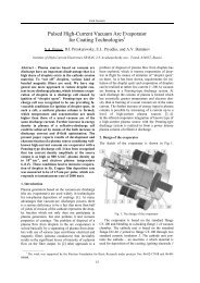
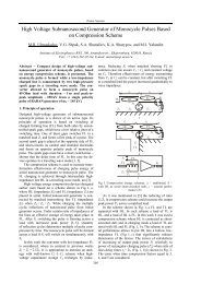
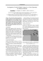
Beam current amplitude, kA<br />
L g-c , cm<br />
Fig. 3. The dependences <strong>of</strong> beam current amplitude on <strong>the</strong><br />
distance L g-c for different charge voltages <strong>of</strong> high-voltage<br />
pulsed generator (HVPG) supplying <strong>the</strong> electron gun.<br />
Н = 1.3 kOe, p = 0.04 Pa, n a = 3 × 10 12 cm –3<br />
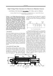
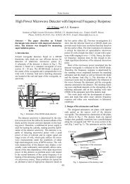
W b , J<br />
Fig. 2. Waveforms <strong>of</strong> acceleration voltage (Ch 1,<br />
10.6 kV/div), cathode current (Ch 2, 14.4 kA/div), and beam<br />
current onto collector (Ch 3, 3 kA/div) obtained at different<br />
distances L g-c . Н = 1.3 kOe, argon pressure is 0.04 Pa,<br />
n a = 3 × 10 12 cm –3<br />
The plots <strong>of</strong> beam current amplitude and beam energy<br />
in dependence on L g-c are given in Figs. 3 and 4.<br />
It is evident, that beam current and energy decrease<br />
ra<strong>the</strong>r faster. The comparison with <strong>the</strong> results obtained<br />
in [1] shows that in <strong>the</strong> stepped tube <strong>the</strong> current and<br />
energy decreasing runs approximately 1.5 times faster<br />
than in <strong>the</strong> case <strong>of</strong> strait tube.<br />
The obtained results show existence <strong>of</strong> beam current<br />
limitation related to <strong>the</strong> processes in <strong>the</strong> drift<br />
channel. The reason <strong>of</strong> this is ra<strong>the</strong>r simple and well<br />
known. At <strong>the</strong> high rate <strong>of</strong> beam rising, its charge neutralization<br />
runs with some delay specified by <strong>the</strong> finite<br />
time <strong>of</strong> plasma electrons going away from <strong>the</strong> drift<br />
83<br />
L g-c , cm<br />
Fig. 4. The dependences <strong>of</strong> beam energy on <strong>the</strong> distance L g-c<br />
for different charge voltages <strong>of</strong>: (1; 4) – 15 kV; (2; 5) –<br />
20 kV; (3; 6) – 30 kV. Plots 1–3 correspond to calorimetrical<br />
data, plots 4–6 obtained by integrating <strong>the</strong> acceleration<br />
voltage and beam current waveforms. Н = 1.3 kOe,<br />
p = 0.04 Pa, n a = 3 × 10 12 cm –3<br />
Estimate roughly <strong>the</strong> current rise rate, at which <strong>the</strong><br />
delay <strong>of</strong> charge neutralization may limit <strong>the</strong> beam current.<br />
Let beam current rises linearly in time and τ is<br />
characteristic time <strong>of</strong> plasma electron going away<br />
from <strong>the</strong> drift channel toward <strong>the</strong> collector. During<br />
this time, beam inputs an excess charge q = I b × τ,<br />
which creates radial, E r , and longitudinal, E z , electric<br />
fields. According to Ostrogradsky–Gauss <strong>the</strong>orem one<br />
can write<br />
2 I<br />
2 2 τ b<br />
dIb<br />
τ<br />
Er<br />
π aL+ Ez<br />
π a = = . (6)<br />
ε dt ε<br />
0 0<br />
Since E r а ≈ E z L ≈ U 0 , so it can be assumed<br />
E r /E z ≈ L/a. Here U 0 is <strong>the</strong> acceleration voltage which<br />
we believe to be equal to potential drop in <strong>the</strong> beam<br />
(<strong>the</strong> condition <strong>of</strong> <strong>the</strong> virtual cathode appearance). After<br />
simple computations, we get
Intense <strong>Electron</strong> and Ion Beams<br />
2 2<br />
⎛ a ⎞ dI τ<br />
U0 1 + ≈ b<br />
⎜<br />
.<br />
2 ⎟<br />
(7).<br />
⎝ L ⎠ dt 2πε0L<br />
Neglecting <strong>the</strong> second item in brackets and assuming<br />
τ = L/(2eU 0 /m) 1/2 , e.g. equal to <strong>the</strong> time flight <strong>of</strong><br />
beam electron without deceleration (minimum time<br />
value), one can get an expression for maximum current<br />
rise rate at exceeding <strong>of</strong> which <strong>the</strong> virtual cathode<br />
may appear:<br />
2<br />
⎛dIb<br />
⎞ 4πε<br />
e<br />
0U0<br />
⎜ ⎟ ≈ .<br />
(8).<br />
⎝ dt ⎠max<br />
mL<br />
Substituting into (8) <strong>the</strong> typical values U 0 = 20 kV<br />
and L = 0.3 m, we get (dI b /dt)max ≈ 2.5 × 10 10 A/s<br />
which is ra<strong>the</strong>r close to those observed in our experiments.<br />
At <strong>the</strong> absence <strong>of</strong> current neutralization, <strong>the</strong><br />
value (dI b /dt)max may be several times lower since<br />
time <strong>of</strong> charge neutralization due to electrostatic ejection<br />
is, at least, two times larger [6].<br />
According to <strong>the</strong> mentioned above, <strong>the</strong> observed<br />
decrease <strong>of</strong> beam current with <strong>the</strong> increasing <strong>of</strong> L becomes<br />
understandable. If <strong>the</strong> length <strong>of</strong> drift channel<br />
increases, so <strong>the</strong> time <strong>of</strong> plasma electron going away<br />
increases also; <strong>the</strong> degree <strong>of</strong> charge neutralization<br />
decreases, hence, <strong>the</strong> decreasing <strong>of</strong> beam current is<br />
observed. The presence <strong>of</strong> <strong>the</strong> step in drift tube in <strong>the</strong><br />
case <strong>of</strong> incomplete beam space charge neutralization<br />
must cause an additional limitation <strong>of</strong> current which<br />
was observed in <strong>the</strong> present work.<br />
As concerned <strong>the</strong> statement <strong>of</strong> Nezlin, that if<br />
plasma density decreases from DL to collector, so <strong>the</strong><br />
virtual cathode must appear, we believe that this<br />
statement is not well-founded enough. Nezlin proceeds<br />
from <strong>the</strong> results <strong>of</strong> experiments [8] in which<br />
such a gradient was created by <strong>the</strong> corresponding gradient<br />
<strong>of</strong> <strong>the</strong> working gas pressure from which plasma<br />
column was formed due to ionization by beam electrons.<br />
But let us pay attention what was <strong>the</strong> concrete<br />
pressure gradient in <strong>the</strong>se experiments. In <strong>the</strong> nearcathode<br />
region, <strong>the</strong> working gas pressure makes up<br />
p 1 = 10 –4 Torr, and at <strong>the</strong> distances <strong>of</strong> tens centimeters<br />
from <strong>the</strong> cathode, <strong>the</strong> pressure was p 2 = 10 –5 Torr. Of<br />
course, in such a situation plasma density in <strong>the</strong> low<br />
pressure region was lower than <strong>the</strong> density <strong>of</strong> electrons<br />
<strong>of</strong> <strong>the</strong> injected beam since in [8] <strong>the</strong> ratio<br />
(eU/kT e ) 1/2 makes up about factor <strong>of</strong> 5–8, e.g. it was<br />
even lower than p 1 /p 2 . At such conditions, from our<br />
point <strong>of</strong> view, beam space charge neutralization was<br />
partial only, and this was <strong>the</strong> reason for virtual cathode<br />
appearance.<br />
4. Conclusions<br />
1. In plasma-filled diode, <strong>the</strong> value <strong>of</strong> beam current is<br />
limited, on one hand, by <strong>the</strong> injection conditions in<br />
double layer between <strong>the</strong> cathode and anode plasmas<br />
according to Eq. (2), and on o<strong>the</strong>r hand, it is limited<br />
by <strong>the</strong> speed <strong>of</strong> beam space charge neutralization in<br />
<strong>the</strong> drift channel.<br />
2. Experiments and estimations show that beam<br />
current may significantly exceed <strong>the</strong> critical currents<br />
<strong>of</strong> aperiodic instabilities responsible to <strong>the</strong> virtual<br />
cathode arising. To achieve this, it is needed <strong>the</strong> excess<br />
plasma with density comparable with <strong>the</strong> density<br />
<strong>of</strong> beam electrons. We believe that such excess plasma<br />
density is enough for suppressing <strong>the</strong> initial fluctuation<br />
<strong>of</strong> <strong>the</strong> beam charge density and potential.<br />
References<br />
[1] G.E. Ozur, S.A. Popov, and M.N. Lazutkin, in<br />
Proc. <strong>of</strong> <strong>the</strong> 13th Symposium on <strong>High</strong> <strong>Current</strong><br />
<strong>Electron</strong>ics, 2004, pp. 60–63.<br />
[2] M.V. Nezlin, Dynamics <strong>of</strong> Beams in Plasma, Moscow,<br />
Energoatomizdat, 1982, pp. 132–149.<br />
[3] E.I. Lutsenko, N.D. Sereda, and A.F. Tseluiko, Zh.<br />
Tekn. Fiz. 58, 1299 (1988).<br />
[4] S.I. Vybornov, A.V. Zharinov, and V.A. Malafaev,<br />
Fizika Plazmy 14, 84 (1988).<br />
[5] A.M. Ignatov and A.A. Rukhadze, Fizika<br />
Plazmy 10, 112 (1984).<br />
[6] A.A. Rukhadze, L.S. Bogdankevich, S.E. Rosinsky,<br />
and V.G. Rukhlin. Physics <strong>of</strong> <strong>High</strong>-<strong>Current</strong><br />
Relativistic <strong>Electron</strong> Beams, Moscow, Energoatomizdat,<br />
1980, 168 p.<br />
[7] V.I. Krementsov, P.S. Strelkov, and A.G. Shquarunets,<br />
Fizika Plazmy 2, 936 (1976).<br />
[8] M.V. Nezlin, Zh. Eksp. Teor. Fiz. 53, 1180 (1967).<br />
84