
Create successful ePaper yourself
Turn your PDF publications into a flip-book with our unique Google optimized e-Paper software.
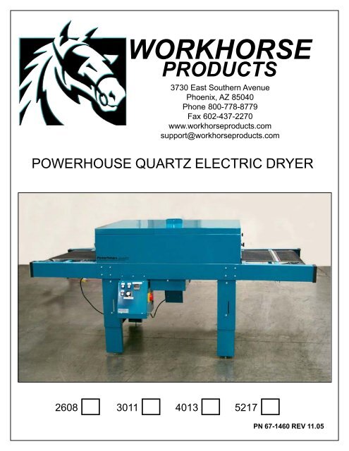
WORKHORSE<br />
PRODUCTS<br />
3730 East Southern Avenue<br />
Phoenix, AZ 85040<br />
Phone 800-778-8779<br />
Fax 602-437-2270<br />
www.workhorseproducts.com<br />
support@workhorseproducts.com<br />
POWERHOUSE QUARTZ ELECTRIC DRYER<br />
2608 3011 4013 5217<br />
PN 67-1460 REV 11.05
Page 2<br />
SAFETY PRECAUTIONS<br />
To ensure safe and reliable operation of your dryer, all operators of this system and personnel<br />
around this system should be thoroughly trained on the following procedures.<br />
1. For your safety, do not store or use gasoline or other flammable vapors and liquids in the<br />
vicinity (at least 3’ (1 Meter)) of this or any other appliance.<br />
2. Vent lines to the outdoors must be installed by a qualified HVAC engineer on all air exhaust<br />
and gas line components equipped with a vent fitting.<br />
3. Proper grounding (a ground rod at the equipment footing), according to NEC requirements,<br />
must be provided for during electrical connection by a QUALIFIED ELECTRICIAN.<br />
4. Never alter the internal wiring of this machine.<br />
5. Never place any item other than the stock to be cured or dried on this dryer’s conveyor belt.<br />
Do not overload the belt.<br />
6. Do not let the conveyor belt track off the conveyor drive rollers.<br />
7. Keep all loose articles (including clothing, hair, jewelry, etc.) away from the conveyor belt.<br />
8. Never leave the machine unattended when it is operating.<br />
9. Do not perform maintenance on this machine until all power has been shut off at the dryer<br />
AND at the incoming power circuit breaker.<br />
THIS ELECTRIC DRYER IS INTENDED SOLELY FOR THE PURPOSE OF CURING INK<br />
ON TO TEXTILE AND CUT GOODS. THIS DRYER IS NOT INTENDED FOR USE IN HEATING,<br />
CURING OR BAKING OF ANY OTHER MATERIALS WHATSOEVER. THIS DRYER IS<br />
INTENDED FOR IN-DOOR USE ONLY<br />
THE EXCLAMATION WITHIN AN EQUILOATERAL TRIANGLE IS INTENDED TO ALERT THE<br />
USER OF IMPORTANT SAFETY PRECAUTIONS SHOP PERSONNEL SHOULD BE AWARE<br />
OF DURING OPERATION.
Page 3
Page 4<br />
1<br />
2<br />
The POWERHOUSE Dryers (2608, 3011, 4013, 5217) Ships in one wooden Crate (Photo 1).<br />
Uncrate using a power Screwdriver (Photo 2).<br />
3 4<br />
4<br />
Remove the shrink wrap ( Photo 3). Then remove the Belt Extentions. DO NOT REMOVE THE<br />
SHRINK WRAP on the Belt Extentions these hold the Belt Rollers in place (Photo 4)<br />
Layout all the Parts<br />
(A) 2-Belt Extentions<br />
(B) 1-Dryer Belt<br />
(C) 1-Parts Bag<br />
(D) Dryer Body<br />
(A)<br />
(A)<br />
(B)<br />
(D)<br />
(E)<br />
(F)<br />
(E) 6-Reflectors<br />
(F) 1-Box with 6<br />
Quartz Elements<br />
inside.<br />
(C)
Page 5<br />
Parts Bag<br />
4 - Stabilizing Bolts<br />
Various Bolts and Nuts<br />
used to attach various<br />
parts of the Dryer.<br />
2 - Element Wrenches<br />
4 - Motor Wire tie<br />
down holders<br />
2 -Spare Ceramic<br />
element stand offs<br />
Step 1 Leveling Dryer<br />
Measure 1/2 " down from the<br />
tip of the Stabilizing Boltsand<br />
put a mark. Then lift one side of<br />
the Dryer Body (before you<br />
attach the Belt Extentions) and<br />
insert into one of the legs.<br />
Hand tighten the Stabilizing<br />
Bolt to the 1/2" mark. After<br />
installing all four Leveling Bolts if<br />
the Dryer rocks Use a 9/16<br />
open end wrench to lightly screw<br />
down the bolt in the leg corner<br />
that is rocking till the bolt<br />
touches the ground and the<br />
dryer stops rocking.<br />
DO NOT try to raise the level of the Dryer with the Stabilizing Bolts and DO NOT use casters<br />
on the Dryer legs as this will cause damage to the metal structure. If the Dryer is not level<br />
lift the Dryer leg that will make it level before you attempt to adjust the Stabilizing Bolt.
Page 6<br />
Step 2 Raising the Dryer / Photo 1<br />
The POWERHOUSE Dryers are shipped with<br />
the Telescoping Legs collapsed. Follow the rest<br />
of Step 2 to raise the Dryer to working height.<br />
Step 2 Raising the Dryer / Photo 2/3<br />
Notice on each of the Telescoping Legs is a<br />
"J" Slot. (Photo 1).<br />
Take 8 of the 5/16 x 3/4" Bolts 8- washers and<br />
8 locking 5/16 flange nuts. You will use 2 Bolt<br />
and Nut sets for each leg.<br />
Put one of the 5/16 x 3/4" Bolts in the hole at<br />
the top of the "J" Slot. (Photo 2) and loosely<br />
tighten the Locking Flange Nut from the<br />
rear. Do this for each leg.<br />
2<br />
3<br />
Step 2 Raising the Dryer / Photo 4<br />
Once you have the Bolts and<br />
Nuts with the washers in each<br />
of the "J" Slots, lift one end of<br />
the Dryer. (two people is best)<br />
Float Arms<br />
The Telescoping leg will slide<br />
down the "J" Slot and secure<br />
itself at the end of the "J" Slot.
Page 7<br />
Step 2 Raising the Dryer / Photos 5/6<br />
Once you have one end of the<br />
POWERHOUSE Dryer raised, lift<br />
the other end. (Photo 5).<br />
When the Dryer is at the working<br />
height tighten the Bolts at the end<br />
of the "J" Slot. for each leg.<br />
Then put another Bolt in the hole<br />
just under the "J" Slot, washer<br />
and Flanged Locking Nut and<br />
tighten. (see insert photo on<br />
Photo 6)<br />
5 6<br />
Step 3 taking Top off Dryer Photo 1<br />
Using a 7/16" wrench remove the Bolts on<br />
all the panels, be careful not to scratch the<br />
painted surface.<br />
Step 3 taking Top off Dryer Photo 2<br />
Once you have unbolted the top panels<br />
remove them one by one. Place them<br />
carefully on a table or the floor.
Page 8<br />
Step 3 taking Top off Dryer Photo 3<br />
POWERHOUSE QUARTZ Dryer<br />
with the top panels off.<br />
Step 4 Install Belt Extensions Photo 1/2<br />
There are two Belt Extensions<br />
the Out Feed Rail Assembly<br />
(the one with the Drive motor<br />
assembly) and the In Feed Rail<br />
Assembly.<br />
To start loosen the bolts on top<br />
of the support rail on the open<br />
end of the Belt Extension, this<br />
helps with alignment. (photo 1)<br />
1 2<br />
Make sure that the Rail Assembly<br />
Cross Support Struts<br />
have the smooth side facing<br />
up.<br />
Insert one end of the Belt Extension into the Belt Extension Slot, push in a little, then line up<br />
the other end and push in. Push both ends in till they line up with the four holes.<br />
Step 4 Install Belt Extensions Photo 3<br />
Once you have lined up the four bolt holes put the<br />
four 5/16 x 3/4" bolts with washers in. Tighten all<br />
eight bolts just enough so you can still move the Belt<br />
Extension with mild force.<br />
Push up on each side of the Belt Extension until it is<br />
level with the main body. Then tighten all eight bolts<br />
securely.
Page 9<br />
Step 4 Install Belt Extensions Photo 4<br />
Install the Out Feed Rail Assembly<br />
(the one with the Drive motor assembly).<br />
Don't forget to loosen the bolts on<br />
top of the support rail on the open end<br />
of the Belt Extension.<br />
Make sure that the Rail Assembly<br />
Cross Support Struts have the smooth<br />
side facing up. The Motor should be<br />
on the same side as the Control Panel.<br />
Attach like the IN Feed Rail Assembly<br />
(Photo 3) by using and tightening the<br />
eight bolts.<br />
Step 4 Install Belt Extensions Photo 5<br />
The POWERHOUSE<br />
QUARTZ Dryer with the<br />
Legs at working height and<br />
both In Feed and Out Feed<br />
Belt Assemblies installed.<br />
The next section will cover installing<br />
and tracking the Dryer Belt
Fig 1<br />
Page 10<br />
INSTALLING THE DRYER BELT<br />
After the Belt Extensions are in place and<br />
locked down feed the Belt OVER the Lower Belt<br />
Extension Brace and through the lower slot<br />
(fig 1)<br />
Fig 2<br />
Keep feeding the Belt through the Heat Chamber<br />
to the other side. (Fig 2)<br />
Fig 3<br />
At the other end feed through the lower slot<br />
and OVER the LOWER Belt Extension Brace.<br />
(Fig 3)<br />
Fig 4<br />
Pull the Belt over the Roller and OVER the TOP<br />
Belt Extension Brace. (fig 4)<br />
Fig 5<br />
Feed the Belt back through the Heat Chamber.<br />
(fig 5).<br />
Keep feeding Belt back through the Heat Chamber<br />
staying on TOP of the Heat Chamber<br />
Braces. (fig 6).
Page 11<br />
Pull the Belt out of the Heat Chamber OVER the<br />
TOP Belt Extension Braces (fig 7)<br />
Fig 7<br />
Pick up the other end of the Belt and lay on top<br />
of the ROLLER and pull the two ends of the Belt<br />
as close as you can get them. (fig 8)<br />
Fig 8<br />
If the Belt does not fit together loosen the Tracking<br />
Bolts at the two ends of the Belt Extensions<br />
and then push the ROLLER in till you can join<br />
the two ends of the Belt. (fig 9 and 10)<br />
Fig 9<br />
Fig 10<br />
Pull out the Joining Pin that is stored in one of<br />
the Belt ends.<br />
Join the two ends of the Belt by interlocking the<br />
ends an then feeding the Joining Pin all the way<br />
through. (fig 11)<br />
After the Belt is centered on the rubber<br />
portion, evenly adjust the Tension Bolts<br />
on all four corners so that the Belt is<br />
just snug and can still be deflected one<br />
to two inches. (fig 12)<br />
Fig 11<br />
Fig 12<br />
Start the Dryer with the Belt running<br />
about 35% and as the Belt heats up<br />
make very SMALL adjustments to keep<br />
the Belt tracking in one position by<br />
turning the adjustment screw Clock<br />
wise to bring the roller end OUT or<br />
Counter Clock wise to push the Roller end in. NOTE: the Belt tends to move in the direction of the<br />
end of the Roller, which it reaches first, so loosen that screw slightly Counter Clock wise. The Belt<br />
may have to be heated up and cooled off several times over a period of days before it will "settle"<br />
into a track.<br />
The belt may not track on the exact middle of the Roller and it is quite possible to track on opposite<br />
ends of each Roller, but still stay tracked in a fixed position. Once the Belt has found it's fixed position<br />
leave it alone.<br />
DO NOT OVER TENSION THE BELT
Page 12<br />
Step 5 Install Quartz Bulb Photo 1<br />
The Quartz Element connections are<br />
located on ceramic stand off's and consist<br />
of a metal clip which the ends of the Elements<br />
are attached to.<br />
You do not need to do any wiring as all<br />
Element wiring is factory installed.<br />
Step 5 Install Quartz Bulb Photo 2<br />
You do not need to do any wiring as all<br />
Element wiring is factory installed.<br />
Carefully unwrap the Quartz Elements and<br />
locate the two Element Wrenches (see<br />
Parts Bag on Page 4). Place one wrench<br />
on the inside Nut on one end of the Element<br />
and while holding the Element firmly<br />
use the other wrench to loosen the front<br />
Nut.<br />
Repeat this procedure for the other end<br />
and for all the Elements.<br />
Step 5 Install Quartz Bulb Photo 3<br />
Open a gap between the two nuts and<br />
washers so that the Element Support Clip<br />
on the Ceramic stand off will fit BETWEEN<br />
the Two WASHERS.
Step 5 Install Quartz Bulb Photo 4<br />
After connecting all six Elements put<br />
the Reflectors on. A Reflector Shield is<br />
placed over each Element.<br />
The slots that you see in Photos 3<br />
and 4 on previous page is where you<br />
lay in the Reflector Sheilds.<br />
Page 13<br />
Step 5 Install Quartz Bulb Photo 5<br />
Either before or after you install the<br />
Reflector Sheilds, use the two Element<br />
Wrenches to tighten the Nuts to make a<br />
Solid Connection for all six Elements on<br />
both sides.<br />
7<br />
Step 6 Hooking up Power Photo 1<br />
The control Panel is located under the Out<br />
Feed Side of the Dryer.<br />
The hole in the side of the Control Panel<br />
is where you put the Power Cord so you<br />
can connect it to the Yellow and Red Main<br />
Disconnect Switch.<br />
This Switch turns off the main power, but<br />
UNPLUG the POWER CORD if doing any<br />
maintenance.<br />
Main Disconnect<br />
Switch<br />
Power Cord<br />
Access
Page 14<br />
Step 6 Routine Cleaning Photo 2<br />
Every 60 to 90 days you need to loosen the four<br />
bolts that hold the motor bracket on the dryer<br />
and clean off excess lint. You also should clean<br />
off the 2 places of vent patterns. These also will<br />
collect lint. Depending on uasge of dryer these<br />
steps may need to be done more frequently.<br />
Step 6 Hooking up Power Photo 3<br />
In order to hook up the Power Cord you need<br />
to remove the cover of the Control panel.<br />
Main Disconnect<br />
Switch<br />
To remove the cover unscrew the four screws<br />
that hold the cover on. The cover has wires<br />
connected to it for the different controls so be<br />
careful how you handle the cover.<br />
Step 6 Hooking up Power Photo 3<br />
Make sure the Main Disconnect Switch is in<br />
the OFF position.<br />
Using the Hole on the inside right of the<br />
Control Box feed the black, white and ground<br />
wire in.<br />
Power Cord<br />
Access<br />
Power Cord<br />
Hook up<br />
Receptacle<br />
Connect the white wire in the first slot of the<br />
Power Cord Hookup Receptacle, the Black<br />
one in the second slot.<br />
The ground wire is hooked up to a ground<br />
screw located right in the back of the Power<br />
Cord Hookup Receptacle. DON'T hook the<br />
ground wire to the Power Cord Hookup Receptacle. Put the Cover back on.
Page 15<br />
CONTROL PANEL DESCRIPTION<br />
The main Disconnect Switch (Yellow and Red) turns on the primary power to the Dryer. The<br />
belt will start to turn and the main recirculating and control panel fans will turn on.<br />
The temperature controller will power up and the process value PV will display the current<br />
ambient temperature sensed inside the Dryer Chamber and the set value SV will display the<br />
last value set for the oven to operate at by the operator.<br />
Toggle Button (A) is the Main on/off Switch. This will start and control all of the elements<br />
together.<br />
(A)<br />
(B)<br />
(C)<br />
(F)<br />
(D)<br />
(E)
Page 16
Page 17
Page 18
Page 19
Page 20
Page 21
Page 22
Page 23<br />
CONTROL CIRCUIT PARTS LIST<br />
Ref Symbol PN Description 2608 3011 4013 5217<br />
Use Per Unit<br />
4FUI-2 39-76177 Fuse ABC5 250vac 2 2 2 2<br />
25FUI-2 76205 Fuse ABC10 250vac 2 2 2 2<br />
BR 20460 Bridge Rectifier 1 1 1 1<br />
CAP 390853 Capacitor 1<br />
CAP 390928 Capacitor 2100mdf 35v 1 1 1<br />
CMSC 76194 Variable Speed Control Board 1 1 1 1<br />
FANI- 2 390934 Axial Fan 230vac 105cfm 1 1 1 1<br />
JTC 20428 Thermocouple J Type 1 1 1 1<br />
MTR 1 390926 BELT DRIVE MOTOR ASSY PHQ DRYERS 1 1 1 1<br />
MTR 2 76153 Motor 60HZ 1/4HP Recalculating for PHQ 1 1 1 1<br />
MTR 2 50HZ 76161 Motor 60HZ 1/4HP Recalculating for PHQ<br />
For 380/415VAC and countries without 60HZ 1 1 1 1<br />
POT 390940-1 Potentiometer Assembly for PHQ Series 1 1 1 1<br />
SW1-3 20450 On/Off Rocker Switch 3 2 2 2<br />
TC 76002 Temperature Control 1 1 1 1<br />
MAIN POWER CIRCUIT PARTS LIST<br />
76175 Fuse Buss NON 35 6 6 6 6
Page 24<br />
ELEMENT CIRCUIT PARTS LIST<br />
Ref PN Description 2608 3011 4013 5217<br />
Symbol Use Per Unit<br />
Quartz 20932 Quartz Element 3 Pack Assembly 104V PHQ-2608 2<br />
Element 1400W Screw Ends (for 208vac)<br />
Quartz 20930 Quartz Element 3pack Assembly 115V PHQ-2608<br />
Element 1400W Screw Ends (for 220-240vac) 2<br />
Quartz 20934 Quartz Element 2608-CAP 2500W Push In<br />
Element Ends 230VAC 1<br />
Quartz 20417 Quartz Element3 Pack Assembly 104V PHQ-30<br />
Element 1000W Screw Ends (for 208vac) 4<br />
Quartz 20414 Quartz Element 3 Pack Assembly 115V PHQ-30<br />
Element 1000W Screw Ends (for 220-240vac) 4<br />
Quartz 20418 Quartz Element 3 Pack Assembly 104V PHQ-40<br />
Element 1500W Screw Ends (for 208vac) 4<br />
Quartz 20415 Quartz Element 3 pack Assembly 115V PHQ-40<br />
Element 1500W Screw Ends (for 220-240vac) 4<br />
Quartz 20419 Quartz Element 2 Pack Assembly 104V PHQ-52<br />
Element 1700W Screw Ends (for 208vac) 8<br />
Quartz 20416 Quartz Element 2 Pack Assembly 115V PHQ-52<br />
Element 1700W Screw Ends (for 220-240vac) 8<br />
42-Hex-8-10 Nut Hex Machine Screw # 8-32 SS 24 48 48 64<br />
81327 Wrench PHQ Element 2 2 2 2<br />
81324 Element Support SS for PHQ Series 12 24 24 32<br />
20420 Quartz Tube for PHQ 2608 & 30 6 12<br />
20421 Quartz Tube for PHQ 40 12<br />
20422 Quartz Tube for PHQ 52 16<br />
20401 Ceramic Stand Off for Element Connector 12 24 24 36<br />
20448 Ceramic End Cap for Screw End Element 12 24 24 36<br />
43-FLT-8-20 Washer Flat #8 SS 24 48 48 64<br />
20928 Coil 104vac 1400W (for 208vac) 6<br />
20926 Coil 115vac 1400W (for 220-240vac) 6<br />
20408 Coil 104vac 1000W (for 208vac) 12<br />
20411 Coil 115vac 1000W (for 220-240vac) 12<br />
20409 Coil 104vac 1500W (for 208vac) 12<br />
20412 Coil 115vac 1500W (for 220-240vac) 12<br />
20410 Coil 104vac 1700W (for 208vac) 18<br />
20413 Coil 115vac 1700W (for 220-240vac) 18<br />
41-PHMS-8-35 Screw Machine SS 8-32 x 3/8 24 48 48 64
Page 25<br />
Exhausting the Unit<br />
Use a qualified HAVAC installer to duct out the room where the unit is located. The suggested method, as shown<br />
below, is to install duct the same size as the units top ring with an in line Air Duct Booster* located 3-4 feet away from<br />
the dryer vent opening. This can be straight up through the ceiling with a mushroom cap or angled 90 degree out through a wall<br />
or the window.<br />
A qualified HAVAC installer can determine the best method. As a substrate enters, passes through, and then exits the<br />
open air dryer chamber, fumes and smoke are generated by the heating of the ink and the substrate. In the case of tee<br />
shirts, chemicals (sizing) are used in the creation process that will smoke when heated.<br />
The smoke is carried by the belt from entry to exit and boils out of both ends. By not venting directly from the oven<br />
you accomplish several things. You do not remove excess heated air (recirculating) out of the oven chamber causing<br />
the unit to work harder, and you capture and remove the smoke and fumes being carried out of the chamber on the belt.<br />
An Air Duct Booster the size of your units top ring will create enough of a draft to sufficiently exhaust the smoke and<br />
fumes.<br />
*Air Duct Booster can be obtained by the HAVAC installer – or one source for the 120V 60HZ booster is Grainger:<br />
Duct 0.0" SP CFM Straight Dims. (In.) Tjernlund Stock 2608 3011 4013 5217<br />
Dia. (In.) CFM @ Duct Lengths(Ft.) L Dia Model No.<br />
150 25<br />
6 180 100 50 6-1/2 6 EF-6 5C963 1<br />
90 75<br />
300 25<br />
8 325 250 50 9 8 EF-8 5C964 1 1 1<br />
200 75<br />
Ceiling<br />
The preferred way to exhaust the<br />
Unit is to purchase a Range Hood<br />
from a store like Home Depot and<br />
attach in the area indicated<br />
Air Duct Booster
Page 26<br />
LIMITED WARRANTY AND WARRANTY REGISTRATION<br />
Although every effort has been made to provide accurate specifications, <strong>Workhorse</strong> <strong>Products</strong>/Odyssey does not assume any<br />
liability for damages, whether consequential or incidental, that may result from the use or misuse of the indicated<br />
specifications. <strong>Workhorse</strong> <strong>Products</strong>/Odyssey requires the use of a licensed industrial electrician for the installation of<br />
electrical service to equipment requiring electrical power.<br />
<strong>Workhorse</strong> <strong>Products</strong>/Odyssey reserves the right to alter specifications in the manufacture of its products.<br />
It is understood and agreed that Seller’s liability for any equipment whether liability in contract, in tort, under any warranty, in<br />
negligence, in strict liability or otherwise shall not exceed the return of the amount of the purchase price paid by Buyer. Not<br />
withstanding the foregoing provision, under no circumstances shall Seller be liable for special, indirect or consequential damages.<br />
The price stated for the equipment is a consideration in limiting Seller’s liability. No action regardless of form, arising out of the<br />
transactions under this Agreement may be brought by Buyer more than one (1) year after the cause of action has occurred. Our<br />
warranty is specified is exclusive and no other warranty, whether written or oral, is expressed or implied. <strong>Workhorse</strong> <strong>Products</strong><br />
specifically disclaims the implied warranties of merchantability and fitness for a particular purpose.<br />
Equipment manufactured or sold by <strong>Workhorse</strong> <strong>Products</strong>/Odyssey is warranted against defects in workmanship and materials for<br />
a period of one year from receipt by customer. All warranties initiate from date of shipment to original customer.<br />
Replacement parts are covered for the term of the equipment warranty period. Parts not under warranty are covered for thirty (30)<br />
days from receipt by customer. Any part found by <strong>Workhorse</strong>/Odyssey to be defective in material or workmanship within the<br />
stated warranty period will be replaced or repaired at <strong>Workhorse</strong>’s option without charge. AFTER OBTAINING AN RMA#<br />
SEND RETURNED FREIGHT PREPAID TO 3730 E. Southern Avenue, PHOENIX, AZ 85040 USA. Written<br />
authorization must be obtained from <strong>Workhorse</strong>/Odyssey before any part will be accepted. Replacement parts are sent out freight<br />
collect. Parts sent out prior to receiving defective part will be sent C.O.D., cost plus freight. Upon return of defective<br />
part, if it is deemed that the part was not damaged by customer but failed, the cost of the replacement part will be<br />
refunded.<br />
This warranty does not extend to expendable parts such as filters, fuses, elements and brushes. <strong>Workhorse</strong> does not warrant<br />
failure of parts or components resulting from misuse or lack of proper maintenance. Installation, inspection, and<br />
maintenance costs are the sole responsibility of the purchaser.<br />
Registration Form<br />
Company Name:<br />
Address:<br />
City:<br />
State:<br />
Country:<br />
Zip Code:<br />
Model Number:<br />
Date Purchased<br />
Contact Name:<br />
Phone Number:<br />
Fax Number:<br />
Email :<br />
Cell Number:<br />
Serial Number:<br />
Date Received:<br />
Please Fax Registration Form for Warranty to take place