EC SERIES - Bosch Hot Water & Heating
EC SERIES - Bosch Hot Water & Heating
EC SERIES - Bosch Hot Water & Heating

Create successful ePaper yourself
Turn your PDF publications into a flip-book with our unique Google optimized e-Paper software.
<strong>EC</strong> <strong>SERIES</strong><br />
Table of Contents<br />
Model Nomenclature ..................................................................................................................1<br />
Introduction....................................................................................................................................2<br />
Initial Inspection............................................................................................................................2<br />
General Description.....................................................................................................................2<br />
Moving and Storage ....................................................................................................................2<br />
Safety Considerations .................................................................................................................2<br />
Location............................................................................................................................................2<br />
Installation.......................................................................................................................................2<br />
Condensate Drain.........................................................................................................................3<br />
Duct System....................................................................................................................................3<br />
Electrical ...........................................................................................................................................4<br />
Piping ................................................................................................................................................4<br />
Well <strong>Water</strong> Systems .....................................................................................................................5<br />
Cooling Tower / Boiler Application........................................................................................5<br />
Earth Coupled Systems...............................................................................................................5<br />
System Checkout ..........................................................................................................................7<br />
Unit Start-Up...................................................................................................................................7<br />
Maintenance...................................................................................................................................8<br />
Operating Pressures & Temperatures ...................................................................................9<br />
Unit Check-Out............................................................................................................................16<br />
Trouble Shooting .......................................................................................................................17<br />
<strong>SERIES</strong>:<br />
<strong>EC</strong><br />
MODEL NOMENCLATURE<br />
<strong>EC</strong> 036 -1 VT C - F L T<br />
NOMINAL CAPACITY:<br />
VOLTAGE DESIGNATION:<br />
0 - 115/1/60<br />
1 - 208/1/60 & 230/1/60<br />
2 - 277/1/60<br />
3 - 208/3/60 & 230/3/60<br />
4 - 460/3/60<br />
5 - 575/3/60<br />
CABINET CONFIGURATION:<br />
VT - VERTICAL<br />
HZ - HORIZONTAL<br />
CF - COUNTERFLOW<br />
HEAT EXCHANGER MATERIAL:<br />
C - COPPER<br />
N - CUPRO-NICKEL<br />
SUPPLY AIR LOCATION:<br />
T - TOP<br />
F - FRONT<br />
R - REAR<br />
S - STRAIGHT THRU<br />
E - END BLOW<br />
B - BOTTOM<br />
RETURN AIR LOCATION:<br />
L - LEFT<br />
R - RIGHT<br />
B - BACK<br />
F - FRONT<br />
WATER CONN<strong>EC</strong>TION<br />
LOCATION:<br />
F - FRONT
2 <strong>EC</strong> <strong>SERIES</strong><br />
INTRODUCTION:<br />
The <strong>EC</strong> Series uses scroll and reciprocating compressors<br />
and refrigerant R-410A to achieve high efficiency levels,<br />
quiet operation and reliable performance.<br />
The new refrigerant provides performance similar to that of<br />
R-22 with one major advantage. Refrigerant R-410A is an<br />
HFC so it does not contain any ozone depleting HCFC's or<br />
CFC's.<br />
INITIAL INSP<strong>EC</strong>TION:<br />
Be certain to inspect all cartons or crates on each unit as<br />
received at the job site before signing the freight bill. Verify<br />
that all items have been received and that there are no<br />
visible damages; note any shortages or damages on all<br />
copies of the freight bill. In the event of damage or<br />
shortage, remember that the purchaser is responsible for<br />
filing the necessary claims with the carrier. Concealed<br />
damages not discovered until after removing the units from<br />
the packaging must be reported to the carrier within 24<br />
hours of receipt.<br />
GENERAL DESCRIPTION:<br />
The <strong>EC</strong> <strong>Water</strong>-to-Air Heat Pumps provide the best<br />
combination of performance and efficiency available.<br />
Safety devices are built into each unit to provide the<br />
maximum system protection possible when properly<br />
installed and maintained.<br />
The <strong>EC</strong> <strong>Water</strong>-to-Air Heat Pumps are Underwriters<br />
Laboratories (UL), (CE) and (CUL) listed for safety. The <strong>EC</strong><br />
<strong>Water</strong>-to-Air Heat Pumps are designed to operate with<br />
entering liquid temperature between 50° F and 100° F. With<br />
the extended range option, the heat pump can operate with<br />
entering liquid temperatures between 25° F and 110° F.<br />
NOTE: 50° F Min. EWT for well water applications with<br />
sufficient water flow to prevent freezing. Antifreeze<br />
solution is required for all closed lop applications.<br />
Cooling Tower/ Boiler and Earth Coupled (GeoThermal)<br />
applications should have sufficient antifreeze solution to<br />
protect against extreme conditions and equipment failure.<br />
Frozen water coils are not covered under warranty.<br />
WARNING: This product should not be used for<br />
temporarily heating/cooling during construction. Doing so<br />
may effect the units warranty.<br />
SAFETY CONSIDERATIONS:<br />
CAUTION: R-410A systems operate at higher pressures<br />
than standard R-22 systems. Do not use R-22 service<br />
equipment or components on R-410A equipment.<br />
Installation and servicing of this equipment can be<br />
hazardous due to system pressure and electrical<br />
components. Only trained and qualified personnel should<br />
install, repair, or service the equipment. Untrained<br />
personnel can perform basic functions of maintenance<br />
such as cleaning coils and replacing filters.<br />
WARNING: Before performing service or maintenance<br />
operations on the system, turn off main power to the unit.<br />
Electrical shock could cause personal injury or death.<br />
When working on equipment, always observe precautions<br />
described in the literature, tags, and labels attached to the<br />
unit. Follow all safety codes. Wear safety glasses and work<br />
gloves. Use a quenching cloth for brazing, and place a fire<br />
extinguisher close to the work area.<br />
LOCATION:<br />
Locate the unit in an indoor area that allows easy removal<br />
of the filter and access panels, and has enough room for<br />
service personnel to perform maintenance or repair.<br />
Provide sufficient room to make water, electrical, and duct<br />
connection(s). If the unit is located in a confined space such<br />
as a closet, provisions must be made for return air to freely<br />
enter the space. On horizontal units, allow adequate room<br />
below the unit for a condensate drain trap and do not<br />
locate the unit above supply piping. These units are not<br />
approved for outdoor installation; therefore, they must be<br />
installed inside the structure being conditioned. Do not<br />
locate in areas that are subject to freezing.<br />
INSTALLATION:<br />
WARNING: Remove all shipping blocks under blower<br />
housing. Loosen compressor mounting bolts.<br />
MOUNTING VERTICAL UNITS:<br />
Vertical units up to five tons are available in left, right, front,<br />
or rear air return configurations. Vertical units should be<br />
mounted level on a vibration absorbing pad slightly larger<br />
than the base to minimize vibration transmission to the<br />
building structure. It is not necessary to anchor the unit to<br />
the floor. (See Figure #1). Vertical units larger than five tons<br />
MOVING AND STORAGE:<br />
If the equipment is not needed for immediate installation<br />
upon its arrival at the job site, it should be left in its<br />
shipping carton and stored in a clean, dry area. Units must<br />
only be stored or moved in the normal upright position as<br />
indicated by the “UP” arrows on each carton at all times. If<br />
unit stacking is required, stack units as follows: Vertical<br />
units less than 6 tons, no more than two high. Horizontal<br />
units less than 6 tons, no more than three high. “Do not<br />
stack units larger than 6 tons.”<br />
(Figure #1)<br />
VIBRATION<br />
PAD<br />
FULL SIZE
<strong>EC</strong> <strong>SERIES</strong><br />
should be vibration isolated according to the design<br />
engineers specifications.<br />
MOUNTING HORIZONTAL UNITS:<br />
While horizontal units may<br />
be installed on any level<br />
surface strong enough to<br />
hold their weight, they are<br />
typically suspended above a<br />
ceiling by threaded rods. The<br />
rods are usually attached to<br />
(Figure #2)<br />
the unit corners by hanger<br />
bracket kits (P/N 930-004, or 006). (See Figure #2). The rods<br />
must be securely anchored to the ceiling. Refer to the<br />
hanging bracket assembly and installation instructions for<br />
details. Units larger than six tons include an integral angle<br />
iron frame with mounting holes present. (See unit<br />
horizontal detail drawing). Horizontal units installed above<br />
the ceiling must conform to all local codes. An auxiliary<br />
drain pan if required by code, should be at least four inches<br />
larger than the bottom of the heat pump. Plumbing<br />
connected to the heat pump must not come in direct<br />
contact with joists, trusses, walls, etc..<br />
Some applications require an attic floor installation of the<br />
horizontal unit. In this case the unit should be set in a full<br />
size secondary drain pan on top of a vibration absorbing<br />
mesh. The secondary drain pan prevents possible<br />
condensate overflow or water leakage damage to the<br />
ceiling. The secondary drain pan is usually placed on a<br />
plywood base isolated from the ceiling joists by additional<br />
layers of vibration absorbing mesh. In both cases, a 3/4"<br />
drain connected to this secondary pan should be run to an<br />
eave at a location that will be noticeable. If the unit is<br />
located in a crawl space, the bottom of the unit must be at<br />
least 4" above grade to prevent flooding of the electrical<br />
parts due to heavy rains.<br />
CONDENSATE DRAIN:<br />
WARNING: If equipped with float style condensate<br />
overflow switch, final adjustment must be made in the<br />
field.<br />
A drain line must be connected to the heat pump and<br />
pitched away from the unit a minimum of 1/8" per foot to<br />
allow the condensate to flow away from the unit.<br />
(Figure #3)<br />
This connection must be in conformance with local<br />
plumbing codes. A trap must be installed in the condensate<br />
line to insure free condensate flow. (Units are not internally<br />
trapped). A vertical air vent is sometimes required to avoid<br />
air pockets. (See Figure #3). The length of the trap depends<br />
on the amount of positive or negative pressure on the<br />
drain pan.<br />
A second trap must not be included. The horizontal unit<br />
should be pitched approximately 1/4" towards the drain in<br />
both directions, to facilitate condensate removal. (See<br />
Figure #4)<br />
(Figure #4)<br />
DUCT SYSTEM:<br />
All <strong>EC</strong> models are provided with a return air duct flange,<br />
while a supply air outlet collar is provided on all models<br />
except the 6 thru 12 ton horizontal models to facilitate duct<br />
connections. Refer to the individual data specification<br />
sheet for physical dimensions of the collar and flange.<br />
A flexible connector is recommended for supply and<br />
return air connections on metal duct systems. All<br />
metal ducting should be insulated with a minimum of<br />
one inch duct insulation to avoid heat loss or gain and<br />
prevent condensate forming during the cooling operation.<br />
Application of the unit to uninsulated duct work is not<br />
recommended as the unit's performance will be adversely<br />
affected. Do not connect discharge ducts directly to the<br />
blower outlet. The factory provided air filter must be<br />
removed when using a filter back return air grill.The factory<br />
filter should be left in place on a free return system.<br />
If the unit will be installed in a new installation with new<br />
duct work, the installation should be designed using<br />
current ASHRAE procedures for duct sizing. If the unit will<br />
be connected to an existing duct system, a check should be<br />
made to assure that the duct system has the capacity to<br />
handle the air required for the unit application. If the duct<br />
system is too small, larger duct work must be installed. Be<br />
certain to check for existing leaks and repair.<br />
The duct system and all diffusers should be sized to handle<br />
the designed air flow quietly. To maximize sound<br />
attenuation of the unit blower, the supply and return air<br />
plenums should be insulated. There should be no direct<br />
straight air path thru the return air grille into the heat<br />
pump. The return air inlet to the heat pump must have at<br />
least one 90 degree turn away from the space return air<br />
grille. If air noise or excessive air flow are a problem, the<br />
blower speed can be changed to a lower speed to reduce<br />
air flow.<br />
3
4 <strong>EC</strong> <strong>SERIES</strong><br />
EL<strong>EC</strong>TRICAL:<br />
All field wiring must comply with local and national fire,<br />
safety and electrical codes. Power to the unit must be<br />
within the operating voltage range indicated on the unit's<br />
nameplate. On three phase units, phases must be balanced<br />
within 2%.<br />
Properly sized fuses or HACR circuit breakers must be<br />
installed for branch circuit protection. See equipment<br />
rating plate for maximum size. The unit is supplied with an<br />
opening for attaching conduit. Be certain to connect the<br />
ground lead to the ground lug in the control box. Connect<br />
the power leads as indicated on the unit wiring diagram.<br />
THERMOSTAT CONN<strong>EC</strong>TIONS:<br />
Thermostat wiring is connected to the 5-position (6-<br />
position on dual compressor models) low voltage terminal<br />
block located in the upper portion of the electrical box. The<br />
thermostat connections and their functions are as follows:<br />
C<br />
O<br />
Y<br />
Y1<br />
Y2<br />
R<br />
G<br />
Transformer 24 VAC Common<br />
Reversing Valve (energized in cooling)<br />
Compressor contactor<br />
1ST stage compressor contractor (dualcompressor<br />
unit)<br />
2ND stage compressor contractor (dualcompressor<br />
unit)<br />
Transformer 24 VAC <strong>Hot</strong><br />
Fan<br />
SAFETY DEVICES AND THE UPM CONTROLLER<br />
Each <strong>EC</strong> unit is factory provided with a Unit Protection<br />
Module (UPM) that controls compressor operation and<br />
monitors the safety controls that protect the unit.<br />
Safety controls include the following:<br />
• High pressure switches located in the refrigerant<br />
discharge lines. One per refrigeration circuit.<br />
• Low pressure switches located in the unit refrigerant<br />
suction lines. One per refrigeration circuit.<br />
• Optional freeze protection sensor located on the<br />
leaving side of the water coil prevents unit operation<br />
below 35ºF. A freeze stat pin located on the board may<br />
be put in the YES or NO position depending whether<br />
the freeze stat is ordered.<br />
NOTE: The factory default is in the YES position. If the<br />
freeze stat option is not ordered the pin must be relocated<br />
to the NO position.<br />
• Optional Condensate overflow protection sensor<br />
located in the drain pan(s) of the unit and wired to the<br />
UPM board.<br />
The UPM includes the following features:<br />
• ANTI-SHORT CYCLE TIMER – 5 minute delay on break<br />
timer to prevent compressor short cycling.<br />
• RANDOM START – Each controller has a unique<br />
random start delay ranging from 270 to 300 seconds.<br />
• LOW PRESSURE BYPASS TIMER - The low pressure<br />
switch is bypassed for 120 seconds after compressor<br />
start-up to prevent nuisance low pressure lockouts<br />
during cold start-up in the heating mode.<br />
• BROWNOUT/SURGE/POWER INTERRUPTION PROT<strong>EC</strong>TION –<br />
a 20 millisecond window is monitored for the above<br />
condition. Should any of these conditions be detected,<br />
the 5-minute delay on break timer and the random<br />
start timer delay are initiated.<br />
• MALFUNCTION OUTPUT – The controller has a set of<br />
wet contacts for remote fault indication.<br />
• TEST SERVICE PIN – A jumper pin is provided to reduce<br />
all time delay settings to 5 seconds during<br />
troubleshooting or verification of unit operation. Note<br />
that operation of the unit in test mode can lead to<br />
accelerated wear and premature failure of the unit.<br />
• L.E.D. FAULT INDICATION – Two L.E.D. indicators are<br />
provided as follows:<br />
One blink<br />
Two blinks<br />
Three blinks<br />
Four blinks<br />
Five blinks<br />
One blink<br />
Two blinks<br />
Three blinks<br />
Four blinks<br />
Five blinks<br />
Six blinks<br />
• GREEN: Power L.E.D. indicates 18 – 30 VAC<br />
present at the board.<br />
• RED: Fault indicator with blink codes as follows:<br />
• INTELLIGENT RESET - If a fault condition is initiated the<br />
5 minute delay on break time period and the random<br />
start timer are initiated and the unit will restart after<br />
these delays expire. During this period the fault LED<br />
will indicate the cause of the fault. If the fault condition<br />
still exists or reoccurs before one hour, the unit will go<br />
into a hard lockout and requires a manual lockout<br />
reset. A condensate overflow fault will cause the unit<br />
to go into a hard lockout immediately.<br />
• LOCKOUT RESET - A hard lockout can be reset by<br />
turning the unit thermostat off and then back on or by<br />
shutting off unit power at the circuit breaker.<br />
NOTE: The blower motor will remain active during a<br />
lockout condition.<br />
PIPING:<br />
SINGLE COMPRESSOR UNITS (UPM-I)<br />
High pressure lockout<br />
Low pressure lockout<br />
Freeze sensor lockout<br />
Condensate overflow<br />
Brownout Conditions<br />
DUAL COMPRESSOR UNITS (UPM-II)<br />
1st Stage high pressure<br />
lockout<br />
1st Stage low pressure lockout<br />
2nd Stage high pressure<br />
lockout<br />
2nd Stage low pressure<br />
lockout<br />
Freeze Protection lockout<br />
Condensate overflow lockout<br />
Supply and return piping must be as large as the unit<br />
connections on the heat pump (larger on long runs). Never<br />
use flexible hoses of a smaller inside diameter than that of
<strong>EC</strong> <strong>SERIES</strong><br />
the water connections on the unit. <strong>EC</strong> Units are supplied<br />
with either a copper or optional cupro-nickel condenser.<br />
Copper is adequate for ground water that is not high in<br />
mineral content. Should your well driller express concern<br />
regarding the quality of the well water available or should<br />
any known hazards exist in your area, we recommend<br />
proper testing to assure the well water quality is suitable<br />
for use with water source equipment. In conditions<br />
anticipating moderate scale formation or in brackish water<br />
a cupro-nickel heat exchanger is recommended.<br />
Both the supply and discharge water lines will sweat if<br />
subjected to low water temperature. These lines should be<br />
insulated to prevent damage from condensation.<br />
All manual flow valves used in the system must be ball<br />
valves. Globe and gate valves must not be used due to high<br />
pressure drop and poor throttling characteristics. Never<br />
exceed the recommended water flow rates. Serious<br />
damage or erosion of the water to refrigerant heat<br />
exchanger could occur.<br />
Always check carefully for water leaks and repair<br />
appropriately. Units are equipped with female pipe thread<br />
fittings. Consult the specification sheets for sizes. Teflon<br />
tape sealer should be used when connecting water piping<br />
connections to the units to insure against leaks and<br />
possible heat exchanger fouling. Do not overtighten the<br />
connections. Flexible hoses should be used between the<br />
unit and the rigid system to avoid possible vibration. Ball<br />
valves should be installed in the supply and return lines for<br />
unit isolation and unit water flow balancing.<br />
Pressure/temperature ports are recommended in both the<br />
supply and return lines for system flow balancing. The<br />
water flow can be accurately set by measuring the waterto-refrigerant<br />
heat exchangers water side pressure drop.<br />
See the unit specification sheets for the water flow and<br />
pressure drop information.<br />
CAUTION: <strong>Water</strong> piping exposed to extreme, low ambient<br />
temperatures is subject to freezing.<br />
WELL WATER SYSTEMS: (50° F EWT Min.)<br />
(Figure #5)<br />
When a water well is used exclusively for supplying water<br />
to the heat pump, the pump should operate only when the<br />
heat pump operates. A 24 volt, double pole single throw<br />
(DP/ST) contactor can be used to operate the well pump<br />
with the heat pump.<br />
When two or more units are supplied from one well, the<br />
pump can be wired to operate independently from either<br />
unit. Two 24-volt double pole single throw relays wired in<br />
parallel are required. An upsized VA transformer may be<br />
required in either case.<br />
The discharge water from the heat pump is not<br />
contaminated in any manner and can be disposed of in<br />
various ways depending on local codes (i.e. discharge well,<br />
dry well, storm sewer, drain field, stream, pond, etc.)<br />
COOLING TOWER / BOILER APPLICATION:<br />
(Figure #6)<br />
To assure adequate cooling and heating performance, the<br />
cooling tower and boiler water loop temperature should be<br />
maintained between 50°F to 75°F in the heating mode and<br />
60°F to 110°F in the cooling mode. In the cooling mode,<br />
heat is rejected from the unit into the water loop. A cooling<br />
tower provides evaporative cooling to the loop fluid; thus,<br />
maintaining a constant supply temperature to the unit.<br />
When utilizing an open cooling tower, chemical water<br />
treatment is mandatory to ensure the water is free of<br />
corrosive materials.<br />
A secondary heat exchanger (plate frame between the unit<br />
and the open cooling tower) may also be used. It is<br />
imperative that all air is eliminated from the closed loop<br />
side of the heat exchanger to prevent condenser fouling.<br />
In the heating mode, heat is absorbed from the water loop<br />
to the unit. A boiler can be utilized to maintain the loop<br />
within the proper temperature range.<br />
No unit should be connected to the supply or return piping<br />
until the water system has been completely cleaned and<br />
flushed to remove dirt, piping chips or other foreign<br />
material. Supply and return hoses should be connected<br />
together during this process to ensure the entire system is<br />
properly flushed. After the cleaning and flushing has taken<br />
place the unit may be connected to the water loop and<br />
should have all valves wide open.<br />
EARTH COUPLED SYSTEMS: (Figure #7)<br />
Operation of an <strong>EC</strong> Series unit on a closed loop application<br />
requires the extended range option.<br />
NOTE: Closed loop and pond applications require<br />
specialized design knowledge. No attempt at these<br />
installations should be made unless the dealer has received<br />
specialized training.<br />
Utilizing Ground Loop Pumping Package (GLP), makes the<br />
installation easy. Anti-freeze solutions must be utilized<br />
when low evaporating conditions are expected to occur.<br />
Refer to the installation manuals for more specific<br />
instructions.<br />
IN-WARRANTY MATERIAL RETURN:<br />
When contacting your FHP Representative for service or<br />
replacement parts, refer to the model and serial number of<br />
the unit as stamped on the data plate attached to the unit.<br />
All warranty material returned to the factory for credit must<br />
be accompanied by a material return material tag. Enter<br />
the information as called for on the tag in order to expedite<br />
handling and insure prompt issuance of credits.<br />
Freight charges for all items returned to the factory shall be<br />
prepaid.The return of the part does not constitute an order<br />
for a replacement. Therefore, a purchase order must be<br />
entered through your nearest representative. The order<br />
shall include the part number, model number, and serial<br />
number of the unit involved. If the part is within the<br />
warranty period, and after our inspection of the returned<br />
part proves that the failure is due to faulty material or<br />
workmanship a credit or replacement part will be issued.<br />
All warranty parts shall be returned freight prepaid to:<br />
FHP Manufacturing Company<br />
601 N.W. 65TH Court • Fort Lauderdale, FL 33309<br />
5
6 <strong>EC</strong> <strong>SERIES</strong><br />
(Figure #5)<br />
WELL WATER APPLICATIONS<br />
(50°F EWT MIN.)<br />
1. LINE VOLTAGE DISCONN<strong>EC</strong>T<br />
2. FLEX DUCT CONN<strong>EC</strong>TION<br />
3. LOW VOLTAGE CONTROL CONN<strong>EC</strong>TION<br />
4. LINE VOLTAGE CONN<strong>EC</strong>TION<br />
5. VIBRATION PAD<br />
6. P/T PORTS<br />
7. HOSE KITS (Optional)<br />
8. BALL VALVES<br />
9. SOLENOID VALVE SLOW CLOSING<br />
10. CONDENSATE DRAIN CONN<strong>EC</strong>TION<br />
11. PRESSURE TANK (Optional)<br />
NOTE: SEE FIGURE #3 FOR CONDENSATE DRAIN<br />
CONN<strong>EC</strong>TION
<strong>EC</strong> <strong>SERIES</strong><br />
SYSTEM CH<strong>EC</strong>KOUT:<br />
• After completing the installation, and before<br />
energizing the unit, the following system checks<br />
should be made:<br />
• Verify that the supply voltage to the heat pump is in<br />
accordance with the nameplate ratings.<br />
• Make sure that all electrical connections are tight and<br />
secure.<br />
• Check the electrical fusing and wiring for the correct<br />
size.<br />
• Verify that the low voltage wiring between the<br />
thermostat and the unit is correct.<br />
• Verify that the water piping is complete and correct.<br />
• Check that the water flow is correct, and adjust if<br />
necessary.<br />
• Check the blower for free rotation, and that it is<br />
secured to the shaft.<br />
• Verify that vibration isolation has been provided.<br />
• Unit is serviceable. Be certain that all access panels are<br />
secured in place.<br />
UNIT START-UP:<br />
1. Set the thermostat to the highest setting.<br />
2. Set the thermostat system switch to "COOL", and the<br />
fan switch to the "AUTO" position. The reversing valve<br />
solenoid should energize. The compressor and fan<br />
should not run.<br />
3. Reduce the thermostat setting approximately 5<br />
degrees below the room temperature.<br />
4. Verify the heat pump is operating in the cooling mode.<br />
5. Turn the thermostat system switch to the "OFF"<br />
position. The unit should stop running and the<br />
reversing valve should deenergize.<br />
6. Leave the unit off for approximately (5) minutes to<br />
allow for system equalization.<br />
7. Turn the thermostat to the lowest setting.<br />
8. Set the thermostat switch to "HEAT".<br />
9. Increase the thermostat setting approximately 5<br />
degrees above the room temperature.<br />
10. Verify the heat pump is operating in the heating mode.<br />
7<br />
(Figure #6)<br />
COOLING TOWER/BOILER APPLICATION<br />
1. LINE VOLTAGE DISCONN<strong>EC</strong>T<br />
2. LOW VOLTAGE CONTROL CONN<strong>EC</strong>TION<br />
3. P/T PLUGS (Optional)<br />
4. HOSE KITS<br />
5. BALL VALVES<br />
6. SUPPLY AND RETURN LINES OF CENTRAL SYSTEM<br />
7. FLEX DUCT CONN<strong>EC</strong>TION<br />
8. HANGING BRACKETS ASSEMBLY (1/2 - 3 1 ⁄2 TON MODELS)<br />
9. THREADED ROD<br />
NOTE: SEE FIGURE #3 FOR CONDENSATE DRAIN CONN<strong>EC</strong>TION
8 <strong>EC</strong> <strong>SERIES</strong><br />
11. Set the thermostat to maintain the desired space<br />
temperature.<br />
12. Check for vibrations, leaks, etc...<br />
13. Instruct the owner on the unit and thermostat<br />
operation.<br />
MAINTENANCE:<br />
1. Filter changes or cleanings are required at regular<br />
intervals. The time period between filter changes will<br />
depend upon type of environment the equipment is<br />
used in. In a single family home, that is not under<br />
construction, changing or cleaning the filter every 60<br />
days is sufficient. In other applications, such as motels,<br />
where daily vacuuming produces a large amount of<br />
lint, filter changes may need to be as frequent as<br />
biweekly.<br />
3. Lubrication of the blower motor is not required,<br />
however, may be performed on some motors to extend<br />
motor life. Use SAE-20 non-detergent electric motor<br />
oil.<br />
4. The condensate drain should be checked annually by<br />
cleaning and flushing to insure proper drainage.<br />
5. Periodic lockouts almost always are caused by air or<br />
water flow problems. The lockout (shutdown) of the<br />
unit is a normal protective measure in the design of the<br />
equipment. If continual lockouts occur call a mechanic<br />
immediately and have them check for: water flow<br />
problems, water temperature problems, air flow<br />
problems or air temperature problems. Use of the<br />
pressure and temperature charts for the unit may be<br />
required to properly determine the cause.<br />
2. An annual ”checkup” is recommended by a licensed<br />
refrigeration mechanic. Recording the performance<br />
measurements of volts, amps, and water temperature<br />
differences (both heating and cooling) is<br />
recommended. This data should be compared to the<br />
information on the unit’s data plate and the data taken<br />
at the original startup of the equipment.<br />
(Figure #7)<br />
EARTH COUPLED APPLICATION<br />
1. LINE VOLTAGE DISCONN<strong>EC</strong>T (UNIT)<br />
2. FLEX DUCT CONN<strong>EC</strong>TION<br />
3. LOW VOLTAGE CONTROL CONN<strong>EC</strong>TION<br />
4. LINE VOLTAGE CONN<strong>EC</strong>TION (UNIT)<br />
5. P/T PORTS<br />
6. VIBRATION PAD<br />
7. CONDENSATE DRAIN<br />
8. GROUND LOOP CONN<strong>EC</strong>TION KIT<br />
9. GROUND LOOP PUMPING PACKAGE (GL001-1 or 002-1)<br />
10. POLYETHELENE WITH INSULATION<br />
11. LINE VOLTAGE DISCONN<strong>EC</strong>T (EL<strong>EC</strong>TRIC HEATER)<br />
NOTE: SEE FIGURE #3 FOR CONDENSATE DRAIN CONN<strong>EC</strong>TION
<strong>EC</strong> <strong>SERIES</strong><br />
MODEL<br />
<strong>EC</strong>007<br />
<strong>EC</strong>009<br />
<strong>EC</strong>012<br />
Operating Temperatures & Pressures, <strong>EC</strong>007-012<br />
ENTERING<br />
WATER<br />
TEMP, ˚F<br />
30˚<br />
40˚<br />
50˚<br />
60˚<br />
70˚<br />
80˚<br />
90˚<br />
100˚<br />
30˚<br />
40˚<br />
50˚<br />
60˚<br />
70˚<br />
80˚<br />
90˚<br />
100˚<br />
30˚<br />
40˚<br />
50˚<br />
60˚<br />
70˚<br />
80˚<br />
90˚<br />
100˚<br />
WATER FLOW<br />
GPM<br />
SUCTION<br />
PRESSURE<br />
PSIG<br />
DISCHARGE<br />
PRESSURE<br />
PSIG<br />
COOLING<br />
WATER<br />
TEMP<br />
RISE, ˚F<br />
OPERATING DATA<br />
AIR<br />
TEMP<br />
DROP, ˚F<br />
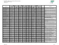
This chart shows approximate temperatures and pressures for a unit in good repair. The values shown are meant as a guide only and should not be used to estimate system<br />
charge. This chart assumes rated air flow and 80º d.b./67º w.b. entering air temperature in cooling, 70º d.b. entering air temperature in heating. <strong>Heating</strong> data at entering fluid<br />
temperatures below 50º assumes the use of antifreeze. Operation in shaded area requires the extended range option.<br />
As a result of continuing research and development, specifications are subject to change without notice.<br />
SUCTION<br />
PRESSURE<br />
PSIG<br />
DISCHARGE<br />
PRESSURE<br />
PSIG<br />
HEATING<br />
WATER<br />
TEMP<br />
DROP, ˚F<br />
AIR<br />
TEMP<br />
RISE, ˚F<br />
1.4 65-80 282-344 6-7 14-17<br />
1.9 73-89 294-359 3-4 15-18<br />
1.4 106-129 146-178 17-21 18-22 80-98 299-365 7-9 16-20<br />
1.9 102-124 133-162 10-13 19-23 89-108 311-380 4-5 17-21<br />
1.4 115-141 180-220 17-20 17-21 95-116 315-385 9-11 19-23<br />
1.9 111-135 163-200 10-12 18-23 105-128 329-402 5-7 20-24<br />
1.4 124-152 213-261 16-19 17-21 109-133 332-406 11-13 21-26<br />
1.9 120-146 194-237 10-12 18-22 121-148 346-423 6-8 22-27<br />
1.4 134-163 247-302 15-19 17-20 124-151 349-427 12-15 23-28<br />
1.9 128-157 225-275 9-11 18-21 138-168 364-444 7-9 25-30<br />
1.4 143-175 281-343 14-18 16-20 138-169 366-447 14-17 26-31<br />
1.9 137-168 255-312 9-11 17-21 154-188 381-466 8-10 27-33<br />
1.4 152-186 315-385 14-17 16-19 153-187 383-468 16-19 28-34<br />
1.9 146-179 286-350 8-10 17-20 170-208 399-487 9-12 29-36<br />
1.4 161-197 349-426 13-16 15-19<br />
1.9 155-190 317-387 8-10 16-20<br />
1.8 91-111 251-307 5-6 21-25<br />
2.4 95-116 256-313 3-4 22-26<br />
1.8 112-137 144-176 14-17 22-27 107-130 267-327 6-7 24-29<br />
2.4 106-130 137-167 10-12 23-28 112-137 273-333 4-5 25-30<br />
1.8 116-142 177-217 13-16 21-26 123-150 284-347 7-9 27-33<br />
2.4 111-135 169-206 9-12 22-27 129-158 289-353 5-6 28-34<br />
1.8 121-148 211-258 13-16 21-26 139-170 300-366 8-10 30-37<br />
2.4 115-140 200-245 9-11 22-27 146-179 306-374 6-7 32-39<br />
1.8 126-154 245-299 13-15 20-25 156-190 316-386 9-12 33-41<br />
2.4 119-146 232-284 9-11 21-26 163-200 322-394 7-8 35-43<br />
1.8 130-159 278-340 12-15 20-24 172-210 332-406 11-13 36-44<br />
2.4 124-151 264-323 9-11 21-26 180-220 339-414 8-9 38-47<br />
1.8 135-165 312-381 12-15 19-24 188-230 349-426 12-15 39-48<br />
2.4 128-157 296-362 9-10 20-25 197-241 355-434 8-10 41-51<br />
1.8 140-171 345-422 12-14 19-23<br />
2.4 133-162 328-401 8-10 20-24<br />
2.6 73-89 266-325 5-6 15-18<br />
3.0 77-94 272-333 3-4 16-19<br />
2.6 117-143 189-231 14-17 18-22 86-105 279-341 6-7 17-21<br />
3.0 112-137 178-217 8-9 19-24 90-110 286-350 4-5 18-22<br />
2.6 126-154 221-270 14-17 18-21 162-198 293-358 7-8 20-24<br />
3.0 121-148 207-253 8-9 19-23 170-208 300-366 5-6 21-25<br />
2.6 131-160 252-308 13-16 17-21 110-134 306-374 8-10 22-27<br />
3.0 125-153 237-290 8-9 18-22 115-141 314-383 6-7 23-29<br />
2.6 135-165 284-347 13-16 17-20 122-150 320-391 9-11 24-30<br />
3.0 130-158 266-326 7-9 18-22 129-157 327-400 6-8 26-32<br />
2.6 140-171 320-391 13-16 16-20 134-164 333-407 11-13 27-33<br />
3.0 134-164 300-367 7-9 17-21 141-172 341-417 7-9 28-35<br />
2.6 144-176 360-440 13-16 16-19 147-179 347-424 12-14 29-36<br />
3.0 138-169 338-414 7-9 17-21 154-188 355-434 8-10 31-38<br />
2.6 149-182 405-495 13-15 15-19<br />
3.0 143-174 381-465 7-9 16-20<br />
9
10<br />
MODEL<br />
<strong>EC</strong>015<br />
<strong>EC</strong>018<br />
<strong>EC</strong>024<br />
<strong>EC</strong> <strong>SERIES</strong><br />
Operating Temperatures & Pressures, <strong>EC</strong>015-024<br />
ENTERING<br />
WATER<br />
TEMP, ˚F<br />
30˚<br />
40˚<br />
50˚<br />
60˚<br />
70˚<br />
80˚<br />
90˚<br />
100˚<br />
30˚<br />
40˚<br />
50˚<br />
60˚<br />
70˚<br />
80˚<br />
90˚<br />
100˚<br />
30˚<br />
40˚<br />
50˚<br />
60˚<br />
70˚<br />
80˚<br />
90˚<br />
100˚<br />
WATER FLOW<br />
GPM<br />
SUCTION<br />
PRESSURE<br />
PSIG<br />
DISCHARGE<br />
PRESSURE<br />
PSIG<br />
COOLING<br />
WATER<br />
TEMP<br />
RISE, ˚F<br />
OPERATING DATA<br />
AIR<br />
TEMP<br />
DROP, ˚F<br />
SUCTION<br />
PRESSURE<br />
PSIG<br />
DISCHARGE<br />
PRESSURE<br />
PSIG<br />
HEATING<br />
WATER<br />
TEMP<br />
DROP, ˚F<br />
AIR<br />
TEMP<br />
RISE, ˚F<br />
2.8 74-90 244-299 3-4 13-15<br />
3.8 78-95 251-306 2-3 13-16<br />
2.8 122-149 183-224 14-18 19-23 87-106 257-314 4-5 15-18<br />
3.8 117-143 172-210 8-10 20-24 91-111 263-322 3-3 16-19<br />
2.8 131-160 214-261 14-18 18-22 164-201 269-329 5-6 17-20<br />
3.8 126-154 201-245 8-10 19-24 173-211 276-337 3-4 18-22<br />
2.8 136-166 244-298 14-17 18-22 111-136 282-344 6-7 19-23<br />
3.8 131-160 230-281 8-10 19-23 117-143 289-353 4-5 20-24<br />
2.8 141-172 275-336 14-17 17-21 124-152 294-360 7-8 21-25<br />
3.8 135-165 258-316 8-10 18-22 131-160 302-369 5-6 22-27<br />
2.8 145-178 310-378 14-17 17-20 136-166 307-375 8-9 23-28<br />
3.8 140-171 291-356 8-10 18-22 143-175 314-384 5-6 24-30<br />
2.8 150-183 349-426 14-17 16-20 149-182 319-390 8-10 25-30<br />
3.8 144-176 328-401 8-9 17-21 156-191 327-400 6-7 26-32<br />
2.8 155-189 392-480 13-16 16-19<br />
3.8 149-182 369-451 8-9 17-21<br />
3.0 65-80 282-344 6-7 14-17<br />
5.0 73-89 294-359 3-4 15-18<br />
3.0 121-148 184-225 17-21 18-22 80-98 299-365 7-9 16-20<br />
5.0 117-143 167-204 10-13 19-23 89-108 311-380 4-5 17-21<br />
3.0 123-151 222-271 17-20 17-21 95-116 315-385 9-11 19-23<br />
5.0 119-145 202-247 10-12 18-23 105-128 329-402 5-7 20-24<br />
3.0 125-153 260-318 16-19 17-21 109-133 332-406 11-13 21-26<br />
5.0 120-147 237-289 10-12 18-22 121-148 346-423 6-8 22-27<br />
3.0 127-155 298-365 15-19 17-20 124-151 349-427 12-15 23-28<br />
5.0 122-149 271-331 9-11 18-21 138-168 364-444 7-9 25-30<br />
3.0 129-158 336-411 14-18 16-20 138-169 366-447 14-17 26-31<br />
5.0 124-152 306-374 9-11 17-21 154-188 381-466 8-10 27-33<br />
3.0 131-160 374-458 14-17 16-19 153-187 383-468 16-16 28-34<br />
5.0 126-154 340-416 8-10 17-20 170-208 399-487 9-12 29-36<br />
3.0 133-162 413-504 13-16 15-19<br />
5.0 128-156 375-458 8-10 16-20<br />
5.0 72-87 296-361 5-6 21-25<br />
7.0 75-92 301-368 3-4 22-26<br />
5.0 114-139 155-190 14-17 22-27 88-107 314-384 6-7 24-29<br />
7.0 108-132 147-180 10-12 23-28 92-112 321-392 4-5 25-30<br />
5.0 116-142 192-234 13-16 21-26 104-127 333-407 7-9 27-33<br />
7.0 111-135 182-222 9-12 22-27 109-133 340-415 5-6 28-34<br />
5.0 119-146 228-279 13-16 21-26 120-146 352-430 8-10 30-37<br />
7.0 113-138 217-265 9-11 22-27 125-153 359-439 6-7 32-39<br />
5.0 122-149 264-323 13-15 20-25 136-166 371-453 9-12 33-41<br />
7.0 116-142 251-307 9-11 21-26 142-174 378-462 7-8 35-43<br />
5.0 125-152 301-368 12-15 20-24 152-185 389-476 11-13 36-44<br />
7.0 118-145 286-349 9-11 21-26 159-194 397-485 8-9 38-47<br />
5.0 127-156 337-412 12-15 19-24 168-205 408-499 12-15 39-48<br />
7.0 121-148 320-392 9-10 20-25 176-215 416-509 8-10 41-51<br />
5.0 130-159 374-457 12-14 19-23<br />
7.0 124-151 355-434 8-10 20-24<br />
This chart shows approximate temperatures and pressures for a unit in good repair. The values shown are meant as a guide only and should not be used to estimate system<br />
charge. This chart assumes rated air flow and 80º d.b./67º w.b. entering air temperature in cooling, 70º d.b. entering air temperature in heating. <strong>Heating</strong> data at entering fluid<br />
temperatures below 50º assumes the use of antifreeze. Operation in shaded area requires the extended range option.<br />
As a result of continuing research and development, specifications are subject to change without notice.
<strong>EC</strong> <strong>SERIES</strong><br />
Operating Temperatures & Pressures, <strong>EC</strong>030-042<br />
11<br />
MODEL<br />
<strong>EC</strong>030<br />
<strong>EC</strong>036<br />
<strong>EC</strong>041<br />
<strong>EC</strong>042<br />
ENTERING<br />
WATER<br />
TEMP, ˚F<br />
30˚<br />
40˚<br />
50˚<br />
60˚<br />
70˚<br />
80˚<br />
90˚<br />
100˚<br />
30˚<br />
40˚<br />
50˚<br />
60˚<br />
70˚<br />
80˚<br />
90˚<br />
100˚<br />
30˚<br />
40˚<br />
50˚<br />
60˚<br />
70˚<br />
80˚<br />
90˚<br />
100˚<br />
WATER FLOW<br />
GPM<br />
SUCTION<br />
PRESSURE<br />
PSIG<br />
DISCHARGE<br />
PRESSURE<br />
PSIG<br />
COOLING<br />
WATER<br />
TEMP<br />
RISE, ˚F<br />
OPERATING DATA<br />
AIR<br />
TEMP<br />
DROP, ˚F<br />
SUCTION<br />
PRESSURE<br />
PSIG<br />
DISCHARGE<br />
PRESSURE<br />
PSIG<br />
HEATING<br />
WATER<br />
TEMP<br />
DROP, ˚F<br />
AIR<br />
TEMP<br />
RISE, ˚F<br />
3.5 73-89 266-325 5-6 15-18<br />
7.5 77-94 272-333 3-4 16-19<br />
3.5 117-143 189-231 14-17 18-22 86-105 279-341 6-7 17-21<br />
7.5 112-137 178-217 8-9 19-24 90-110 286-350 4-5 18-22<br />
3.5 126-154 221-270 14-17 18-21 162-198 293-358 7-8 20-24<br />
7.5 121-148 207-253 8-9 19-23 170-208 300-366 5-6 21-25<br />
3.5 131-160 252-308 13-16 17-21 110-134 306-374 8-10 22-27<br />
7.5 125-153 237-290 8-9 18-22 115-141 314-383 6-7 23-29<br />
3.5 135-165 284-347 13-16 17-20 122-150 320-391 9-11 24-30<br />
7.5 130-158 266-326 7-9 18-22 129-157 327-400 6-8 26-32<br />
3.5 140-171 320-391 13-16 16-20 134-164 333-407 11-13 27-33<br />
7.5 134-164 300-367 7-9 17-21 141-172 341-417 7-9 28-35<br />
3.5 144-176 360-440 13-16 16-19 147-179 347-424 12-14 29-36<br />
7.5 138-169 338-414 7-9 17-21 154-188 355-434 8-10 31-38<br />
3.5 149-182 405-495 13-15 15-19<br />
7.5 143-174 381-465 7-9 16-20<br />
4.5 74-90 244-299 3-4 13-15<br />
9.0 78-95 251-306 2-3 13-16<br />
4.5 122-149 183-224 14-18 19-23 87-106 257-314 4-5 15-18<br />
9.0 117-143 172-210 8-10 20-24 91-111 263-322 3-3 16-19<br />
4.5 131-160 214-261 14-18 18-22 164-201 269-329 5-6 17-20<br />
9.0 126-154 201-245 8-10 19-24 173-211 276-337 3-4 18-22<br />
4.5 136-166 244-298 14-17 18-22 111-136 282-344 6-7 19-23<br />
9.0 131-160 230-281 8-10 19-23 117-143 289-353 4-5 20-24<br />
4.5 141-172 275-336 14-17 17-21 124-152 294-360 7-8 21-25<br />
9.0 135-165 258-316 8-10 18-22 131-160 302-369 5-6 22-27<br />
4.5 145-178 310-378 14-17 17-20 136-166 307-375 8-9 23-28<br />
9.0 140-171 291-356 8-10 18-22 143-175 314-384 5-6 24-30<br />
4.5 150-183 349-426 14-17 16-20 149-182 319-390 8-10 25-30<br />
9.0 144-176 328-401 8-9 17-21 156-191 327-400 6-7 26-32<br />
4.5 155-189 392-480 13-16 16-19<br />
9.0 149-182 369-451 8-9 17-21<br />
6.0 64-78 248-303 5-6 15-18<br />
10.0 67-82 254-311 3-4 16-19<br />
6.0 109-134 183-224 18-22 19-23 75-91 261-319 6-8 17-21<br />
10.0 105-128 172-210 10-12 20-25 79-96 267-327 4-5 18-23<br />
6.0 118-144 214-261 18-22 19-23 142-173 273-334 8-10 20-24<br />
10.0 113-138 201-245 10-12 20-24 149-182 280-342 5-7 21-26<br />
6.0 122-149 244-298 17-21 18-22 96-117 286-349 9-11 22-27<br />
10.0 117-143 230-281 10-12 19-24 101-123 293-358 6-8 24-29<br />
6.0 126-154 275-336 17-21 18-22 107-131 299-365 11-13 25-30<br />
10.0 121-148 258-316 10-12 19-23 113-138 306-374 7-9 26-32<br />
6.0 130-159 310-378 17-21 17-21 117-143 311-380 12-15 27-33<br />
10.0 125-153 291-356 10-12 18-22 123-151 319-390 8-10 29-35<br />
6.0 134-164 349-426 17-20 17-20 128-157 324-396 13-16 29-36<br />
10.0 129-158 328-401 9-12 18-22 135-165 332-406 9-11 31-38<br />
6.0 139-170 392-480 16-20 16-20<br />
10.0 133-163 369-451 9-11 17-21<br />
This chart shows approximate temperatures and pressures for a unit in good repair. The values shown are meant as a guide only and should not be used to estimate system<br />
charge. This chart assumes rated air flow and 80º d.b./67º w.b. entering air temperature in cooling, 70º d.b. entering air temperature in heating. <strong>Heating</strong> data at entering fluid<br />
temperatures below 50º assumes the use of antifreeze. Operation in shaded area requires the extended range option.<br />
As a result of continuing research and development, specifications are subject to change without notice.
12<br />
MODEL<br />
<strong>EC</strong>048<br />
<strong>EC</strong>051<br />
<strong>EC</strong>060<br />
<strong>EC</strong>061<br />
<strong>EC</strong>070<br />
Operating Temperatures & Pressures, <strong>EC</strong>048-070<br />
ENTERING<br />
WATER<br />
TEMP, ˚F<br />
30˚<br />
40˚<br />
50˚<br />
60˚<br />
70˚<br />
80˚<br />
90˚<br />
100˚<br />
30˚<br />
40˚<br />
50˚<br />
60˚<br />
70˚<br />
80˚<br />
90˚<br />
100˚<br />
30˚<br />
40˚<br />
50˚<br />
60˚<br />
70˚<br />
80˚<br />
90˚<br />
100˚<br />
WATER FLOW<br />
GPM<br />
SUCTION<br />
PRESSURE<br />
PSIG<br />
DISCHARGE<br />
PRESSURE<br />
PSIG<br />
COOLING<br />
WATER<br />
TEMP<br />
RISE, ˚F<br />
OPERATING DATA<br />
AIR<br />
TEMP<br />
DROP, ˚F<br />
This chart shows approximate temperatures and pressures for a unit in good repair. The values shown are meant as a guide only and should not be used to estimate system<br />
charge. This chart assumes rated air flow and 80º d.b./67º w.b. entering air temperature in cooling, 70º d.b. entering air temperature in heating. <strong>Heating</strong> data at entering fluid<br />
temperatures below 50º assumes the use of antifreeze. Operation in shaded area requires the extended range option.<br />
As a result of continuing research and development, specifications are subject to change without notice.<br />
SUCTION<br />
PRESSURE<br />
PSIG<br />
DISCHARGE<br />
PRESSURE<br />
PSIG<br />
HEATING<br />
WATER<br />
TEMP<br />
DROP, ˚F<br />
<strong>EC</strong> <strong>SERIES</strong><br />
AIR<br />
TEMP<br />
RISE, ˚F<br />
6.0 71-87 277-339 6-7 15-19<br />
10.0 75-92 284-347 4-5 16-20<br />
6.0 118-144 194-237 21-25 19-23 84-102 291-356 7-9 18-22<br />
10.0 113-138 182-223 12-14 20-24 88-108 299-365 5-6 19-23<br />
6.0 127-155 226-276 21-25 18-22 159-194 305-373 9-11 20-25<br />
10.0 122-149 213-260 12-14 19-24 167-204 313-383 6-7 21-26<br />
6.0 131-160 259-316 21-25 18-22 108-132 320-391 10-13 23-28<br />
10.0 126-154 243-297 12-14 19-23 113-138 328-400 7-9 24-29<br />
6.0 136-166 291-355 20-25 17-21 120-147 334-408 12-15 25-31<br />
10.0 130-159 273-334 12-14 18-22 126-154 342-418 8-10 27-32<br />
6.0 140-171 328-401 20-24 17-20 131-161 348-425 14-17 27-34<br />
10.0 135-165 308-377 11-14 18-22 138-169 356-436 9-11 29-36<br />
6.0 145-177 369-451 20-24 16-20 144-176 362-442 15-18 30-37<br />
10.0 139-170 347-424 11-14 17-21 151-185 371-453 10-12 32-39<br />
6.0 149-183 415-508 19-24 16-19<br />
10.0 143-175 391-477 11-14 17-21<br />
8.0 68-84 256-313 5-7 19-23<br />
12.0 73-89 261-319 4-5 20-25<br />
8.0 113-138 173-212 18-22 19-23 81-99 277-339 7-8 22-26<br />
12.0 110-134 162-198 12-14 20-24 86-105 283-346 5-6 23-28<br />
8.0 116-142 207-253 17-21 19-23 93-114 299-365 8-9 24-29<br />
12.0 112-137 193-236 12-14 19-24 99-121 305-373 6-7 25-31<br />
8.0 118-145 240-293 17-21 18-23 106-129 321-392 9-11 26-32<br />
12.0 115-140 224-274 11-14 19-23 113-138 327-400 7-8 28-34<br />
8.0 121-148 273-334 17-21 18-22 118-145 342-418 10-12 29-35<br />
12.0 117-143 255-312 11-14 19-23 126-154 349-427 8-9 30-37<br />
8.0 123-151 307-375 16-20 18-22 131-160 364-444 11-14 31-38<br />
12.0 120-146 287-350 11-13 19-23 139-170 371-454 8-10 33-40<br />
8.0 126-154 340-416 16-20 18-22 143-175 385-471 12-15 33-41<br />
12.0 122-149 318-388 11-13 18-22 152-186 393-480 9-11 35-43<br />
8.0 128-157 373-456 16-19 17-21<br />
12.0 125-152 349-426 11-13 18-22<br />
12.0 68-84 256-313 5-7 19-23<br />
16.0 73-89 261-319 4-5 20-25<br />
12.0 117-143 182-222 15-19 21-26 81-99 277-339 7-8 22-26<br />
16.0 114-139 170-208 11-14 22-27 86-105 283-346 5-6 23-28<br />
12.0 120-147 215-263 15-18 20-25 93-114 299-365 8-9 24-29<br />
16.0 117-143 201-246 11-14 21-26 99-121 305-373 6-7 25-31<br />
12.0 123-150 248-304 14-17 20-24 106-129 321-392 9-11 26-32<br />
16.0 119-146 232-284 11-13 21-25 113-138 327-400 7-8 28-34<br />
12.0 126-154 282-344 14-17 19-24 118-145 342-418 10-12 29-35<br />
16.0 122-149 263-322 10-13 20-25 126-154 349-427 8-9 30-37<br />
12.0 129-157 315-385 13-16 19-23 131-160 364-444 11-14 31-38<br />
16.0 125-153 294-360 10-12 19-24 139-170 371-454 8-10 33-40<br />
12.0 132-161 348-426 13-16 18-22 143-175 385-471 12-15 33-41<br />
16.0 128-156 326-398 10-12 19-23 152-186 393-480 9-11 35-43<br />
12.0 134-164 382-466 12-15 17-21<br />
16.0 131-160 357-436 9-11 18-22
<strong>EC</strong> <strong>SERIES</strong><br />
Operating Temperatures & Pressures, <strong>EC</strong>072-120<br />
13<br />
MODEL<br />
<strong>EC</strong>072<br />
<strong>EC</strong>096<br />
<strong>EC</strong>120<br />
ENTERING<br />
WATER<br />
TEMP, ˚F<br />
30˚<br />
40˚<br />
50˚<br />
60˚<br />
70˚<br />
80˚<br />
90˚<br />
100˚<br />
30˚<br />
40˚<br />
50˚<br />
60˚<br />
70˚<br />
80˚<br />
90˚<br />
100˚<br />
30˚<br />
40˚<br />
50˚<br />
60˚<br />
70˚<br />
80˚<br />
90˚<br />
100˚<br />
WATER FLOW<br />
GPM<br />
SUCTION<br />
PRESSURE<br />
PSIG<br />
DISCHARGE<br />
PRESSURE<br />
PSIG<br />
COOLING<br />
WATER<br />
TEMP<br />
RISE, ˚F<br />
OPERATING DATA<br />
AIR<br />
TEMP<br />
DROP, ˚F<br />
SUCTION<br />
PRESSURE<br />
PSIG<br />
DISCHARGE<br />
PRESSURE<br />
PSIG<br />
HEATING<br />
WATER<br />
TEMP<br />
DROP, ˚F<br />
AIR<br />
TEMP<br />
RISE, ˚F<br />
10.0 65-80 282-344 6-7 14-17<br />
16.0 73-89 294-359 3-4 15-18<br />
10.0 121-148 184-225 17-21 18-22 80-98 299-365 7-9 16-20<br />
16.0 117-143 167-204 10-13 19-23 89-108 311-380 4-5 17-21<br />
10.0 123-151 222-271 17-20 17-21 95-116 315-385 9-11 19-23<br />
16.0 119-145 202-247 10-12 18-23 105-128 329-402 5-7 20-24<br />
10.0 125-153 260-318 16-19 17-21 109-133 332-406 11-13 21-26<br />
16.0 120-147 237-289 10-12 18-22 121-148 346-423 6-8 22-27<br />
10.0 127-155 298-365 15-19 17-20 124-151 349-427 12-15 23-28<br />
16.0 122-149 271-331 9-11 18-21 138-168 364-444 7-9 25-30<br />
10.0 129-158 336-411 14-18 16-20 138-169 366-447 14-17 26-31<br />
16.0 124-152 306-374 9-11 17-21 154-188 381-466 8-10 27-33<br />
10.0 131-160 374-458 14-17 16-19 153-187 383-468 16-19 28-34<br />
16.0 126-154 340-416 8-10 17-20 170-208 399-487 9-12 29-36<br />
10.0 133-162 413-504 13-16 15-19<br />
16.0 128-156 375-458 8-10 16-20<br />
13.0 72-87 296-361 5-6 21-25<br />
22.0 75-92 301-368 3-4 22-26<br />
13.0 114-139 155-190 14-17 22-27 88-107 314-384 6-7 24-29<br />
22.0 108-132 147-180 10-12 23-28 92-112 321-392 4-5 25-30<br />
13.0 116-142 192-234 13-16 21-26 104-127 333-407 7-9 27-33<br />
22.0 111-135 182-222 9-12 22-27 109-133 340-415 5-6 28-34<br />
13.0 119-146 228-279 13-16 21-26 120-146 352-430 8-10 30-37<br />
22.0 113-138 217-265 9-11 22-27 125-153 359-439 6-7 32-39<br />
13.0 122-149 264-323 13-15 20-25 136-166 371-453 9-12 33-41<br />
22.0 116-142 251-307 9-11 21-26 142-174 378-462 7-8 35-43<br />
13.0 125-152 301-368 12-15 20-24 152-185 389-476 11-13 36-44<br />
22.0 118-145 286-349 9-11 21-26 159-194 397-485 8-9 38-47<br />
13.0 127-156 337-412 12-15 19-24 168-205 408-499 12-15 39-48<br />
22.0 121-148 320-392 9-10 20-25 176-215 416-509 8-10 41-51<br />
13.0 130-159 374-457 12-14 19-23<br />
22.0 124-151 355-434 8-10 20-24<br />
16.0 73-89 266-325 5-6 15-18<br />
32.0 77-94 272-333 3-4 16-19<br />
16.0 117-143 189-231 14-17 18-22 86-105 279-341 6-7 17-21<br />
32.0 112-137 178-217 8-9 19-24 90-110 286-350 4-5 18-22<br />
16.0 126-154 221-270 14-17 18-21 162-198 293-358 7-8 20-24<br />
32.0 121-148 207-253 8-9 19-23 170-208 300-366 5-6 21-25<br />
16.0 131-160 252-308 13-16 17-21 110-134 306-374 8-10 22-27<br />
32.0 125-153 237-290 8-9 18-22 115-141 314-383 6-7 23-29<br />
16.0 135-165 284-347 13-16 17-20 122-150 320-391 9-11 24-30<br />
32.0 130-158 266-326 7-9 18-22 129-157 327-400 6-8 26-32<br />
16.0 140-171 320-391 13-16 16-20 134-164 333-407 11-13 27-33<br />
32.0 134-164 300-367 7-9 17-21 141-172 341-417 7-9 28-35<br />
16.0 144-176 360-440 13-16 16-19 147-179 347-424 12-14 29-36<br />
32.0 138-169 338-414 7-9 17-21 154-188 355-434 8-10 31-38<br />
16.0 149-182 405-495 13-15 15-19<br />
32.0 143-174 381-465 7-9 16-20<br />
This chart shows approximate temperatures and pressures for a unit in good repair. The values shown are meant as a guide only and should not be used to estimate system<br />
charge. This chart assumes rated air flow and 80º d.b./67º w.b. entering air temperature in cooling, 70º d.b. entering air temperature in heating. <strong>Heating</strong> data at entering fluid<br />
temperatures below 50º assumes the use of antifreeze. Operation in shaded area requires the extended range option.<br />
As a result of continuing research and development, specifications are subject to change without notice.
14<br />
MODEL<br />
<strong>EC</strong>150<br />
<strong>EC</strong>180<br />
<strong>EC</strong>210<br />
Operating Temperatures & Pressures, <strong>EC</strong>150-210<br />
ENTERING<br />
WATER<br />
TEMP, ˚F<br />
30˚<br />
40˚<br />
50˚<br />
60˚<br />
70˚<br />
80˚<br />
90˚<br />
100˚<br />
30˚<br />
40˚<br />
50˚<br />
60˚<br />
70˚<br />
80˚<br />
90˚<br />
100˚<br />
30˚<br />
40˚<br />
50˚<br />
60˚<br />
70˚<br />
80˚<br />
90˚<br />
100˚<br />
WATER FLOW<br />
GPM<br />
SUCTION<br />
PRESSURE<br />
PSIG<br />
DISCHARGE<br />
PRESSURE<br />
PSIG<br />
COOLING<br />
WATER<br />
TEMP<br />
RISE, ˚F<br />
OPERATING DATA<br />
AIR<br />
TEMP<br />
DROP, ˚F<br />
SUCTION<br />
PRESSURE<br />
PSIG<br />
DISCHARGE<br />
PRESSURE<br />
PSIG<br />
HEATING<br />
WATER<br />
TEMP<br />
DROP, ˚F<br />
<strong>EC</strong> <strong>SERIES</strong><br />
AIR<br />
TEMP<br />
RISE, ˚F<br />
22.0 74-90 244-299 3-4 13-15<br />
38.0 78-95 251-306 2-3 13-16<br />
22.0 122-149 183-224 14-18 19-23 87-106 257-314 4-5 15-18<br />
38.0 117-143 172-210 8-10 20-24 91-111 263-322 3-3 16-19<br />
22.0 131-160 214-261 14-18 18-22 164-201 269-329 5-6 17-20<br />
38.0 126-154 201-245 8-10 19-24 173-211 276-337 3-4 18-22<br />
22.0 136-166 244-298 14-17 18-22 111-136 282-344 6-7 19-23<br />
38.0 131-160 230-281 8-10 19-23 117-143 289-353 4-5 20-24<br />
22.0 141-172 275-336 14-17 17-21 124-152 294-360 7-8 21-25<br />
38.0 135-165 258-316 8-10 18-22 131-160 302-369 5-6 22-27<br />
22.0 145-178 310-378 14-17 17-20 136-166 307-375 8-9 23-28<br />
38.0 140-171 291-356 8-10 18-22 143-175 314-384 5-6 24-30<br />
22.0 150-183 349-426 14-17 16-19 149-182 319-390 8-10 25-30<br />
38.0 144-176 328-401 8-9 17-21 156-191 327-400 6-7 26-32<br />
22.0 155-189 392-480 13-16 16-19<br />
38.0 149-182 369-451 8-9 17-21<br />
25.0 64-78 248-303 5-6 15-18<br />
45.0 67-82 254-311 3-4 16-19<br />
25.0 109-134 183-224 18-22 19-23 75-91 261-319 6-8 17-21<br />
45.0 105-128 172-210 10-12 20-25 79-96 267-327 4-5 18-23<br />
25.0 118-144 214-261 18-22 19-23 142-173 273-334 8-10 20-24<br />
45.0 113-138 201-245 10-12 20-24 149-182 280-342 5-7 21-26<br />
25.0 122-149 244-298 17-21 18-22 96-117 286-349 9-11 22-27<br />
45.0 117-143 230-281 10-12 19-24 101-123 293-358 6-8 24-29<br />
25.0 126-154 275-336 17-21 18-22 107-131 299-365 11-13 25-30<br />
45.0 121-148 258-316 10-12 19-23 113-138 306-374 7-9 26-32<br />
25.0 130-159 310-378 17-21 17-21 117-143 311-380 12-15 27-33<br />
45.0 125-153 291-356 10-12 18-22 123-151 319-390 8-10 29-35<br />
25.0 134-164 349-426 17-20 17-20 128-157 324-396 13-16 29-36<br />
45.0 129-158 328-401 9-12 18-22 135-165 332-406 9-11 31-38<br />
25.0 139-170 392-480 16-20 16-20<br />
45.0 133-163 369-451 9-11 17-21<br />
28.0 71-87 277-339 6-7 15-19<br />
52.0 75-92 284-347 4-5 16-20<br />
28.0 118-144 194-237 21-25 19-23 84-102 291-356 7-9 18-22<br />
52.0 113-138 182-223 12-14 20-24 88-108 299-365 5-6 19-23<br />
28.0 127-155 226-276 21-25 18-22 159-194 305-373 9-11 20-25<br />
52.0 122-149 213-260 12-14 19-24 167-204 313-383 6-7 21-26<br />
28.0 131-160 259-316 21-25 18-22 108-132 320-391 10-13 23-28<br />
52.0 126-154 243-297 12-14 19-23 113-138 328-400 7-9 24-29<br />
28.0 136-166 291-355 20-25 17-21 120-147 334-408 12-15 25-31<br />
52.0 130-159 273-334 12-14 18-22 126-154 342-418 8-10 27-32<br />
28.0 140-171 328-401 20-24 17-20 131-161 348-425 14-17 27-34<br />
52.0 135-165 308-377 11-14 18-22 138-169 356-436 9-11 29-36<br />
28.0 145-177 369-451 20-24 16-20 144-176 362-442 15-18 30-37<br />
52.0 139-170 347-424 11-14 17-21 151-185 371-453 10-12 32-39<br />
28.0 149-183 415-508 19-24 16-19<br />
52.0 143-175 391-477 11-14 17-21<br />
This chart shows approximate temperatures and pressures for a unit in good repair. The values shown are meant as a guide only and should not be used to estimate system<br />
charge. This chart assumes rated air flow and 80º d.b./67º w.b. entering air temperature in cooling, 70º d.b. entering air temperature in heating. <strong>Heating</strong> data at entering fluid<br />
temperatures below 50º assumes the use of antifreeze. Operation in shaded area requires the extended range option.<br />
As a result of continuing research and development, specifications are subject to change without notice.
<strong>EC</strong> <strong>SERIES</strong><br />
MODEL<br />
<strong>EC</strong>240<br />
<strong>EC</strong>300<br />
<strong>EC</strong>360<br />
Operating Temperatures & Pressures, <strong>EC</strong>240-360<br />
ENTERING<br />
WATER<br />
TEMP, ˚F<br />
30˚<br />
40˚<br />
50˚<br />
60˚<br />
70˚<br />
80˚<br />
90˚<br />
100˚<br />
30˚<br />
40˚<br />
50˚<br />
60˚<br />
70˚<br />
80˚<br />
90˚<br />
100˚<br />
30˚<br />
40˚<br />
50˚<br />
60˚<br />
70˚<br />
80˚<br />
90˚<br />
100˚<br />
WATER FLOW<br />
GPM<br />
SUCTION<br />
PRESSURE<br />
PSIG<br />
DISCHARGE<br />
PRESSURE<br />
PSIG<br />
COOLING<br />
WATER<br />
TEMP<br />
RISE, ˚F<br />
OPERATING DATA<br />
AIR<br />
TEMP<br />
DROP, ˚F<br />
SUCTION<br />
PRESSURE<br />
PSIG<br />
DISCHARGE<br />
PRESSURE<br />
PSIG<br />
HEATING<br />
WATER<br />
TEMP<br />
DROP, ˚F<br />
AIR<br />
TEMP<br />
RISE, ˚F<br />
32.0 68-84 256-313 5-7 19-23<br />
64.0 73-89 261-319 4-5 20-25<br />
32.0 113-138 172-210 18-22 19-23 81-99 277-339 7-8 22-26<br />
64.0 110-134 161-196 12-14 20-24 86-105 283-346 5-6 23-28<br />
32.0 116-142 206-252 17-21 19-23 93-114 299-365 8-9 24-29<br />
64.0 112-137 193-236 12-14 19-24 99-121 305-373 6-7 25-31<br />
32.0 118-145 241-294 17-21 18-23 106-129 321-392 9-11 26-32<br />
64.0 115-140 225-275 11-14 19-23 113-138 327-400 7-8 28-34<br />
32.0 121-148 275-336 17-21 18-22 118-145 342-418 10-12 29-35<br />
64.0 117-143 257-314 11-14 19-23 126-154 349-427 8-9 30-37<br />
32.0 123-151 309-378 16-20 18-22 131-160 364-444 11-14 31-38<br />
64.0 120-146 289-353 11-13 19-23 139-170 371-454 8-10 33-40<br />
32.0 126-154 344-420 16-20 18-22 143-175 385-471 12-15 33-41<br />
64.0 122-149 321-392 11-13 18-22 152-186 393-480 9-11 35-43<br />
32.0 128-157 378-462 16-19 17-21<br />
64.0 125-152 353-432 11-13 18-22<br />
45.0 68-84 256-313 5-7 19-23<br />
75.0 73-89 261-319 4-5 20-25<br />
45.0 117-143 210-256 15-19 21-26 81-99 277-339 7-8 22-26<br />
75.0 114-139 196-239 11-14 22-27 86-105 283-346 5-6 23-28<br />
45.0 120-147 243-297 15-18 20-25 93-114 299-365 8-9 24-29<br />
75.0 117-143 227-277 11-14 21-26 99-121 305-373 6-7 25-31<br />
45.0 123-150 276-337 14-17 20-24 106-129 321-392 9-11 26-32<br />
75.0 119-146 258-315 11-13 21-25 113-138 327-400 7-8 28-34<br />
45.0 126-154 309-378 14-17 19-24 118-145 342-418 10-12 29-35<br />
75.0 122-149 289-353 10-13 20-25 126-154 349-427 8-9 30-37<br />
45.0 129-157 343-419 13-16 19-23 131-160 364-444 11-14 31-38<br />
75.0 125-153 320-391 10-12 19-24 139-170 371-454 8-10 33-40<br />
45.0 132-161 376-459 13-16 18-22 143-175 385-471 12-15 33-41<br />
75.0 128-156 351-429 10-12 19-23 152-186 393-480 9-11 35-43<br />
45.0 134-164 409-500 12-15 17-21<br />
75.0 131-160 382-467 9-11 18-22<br />
50.0 65-80 282-344 6-7 14-17<br />
90.0 73-89 294-359 3-4 15-18<br />
50.0 121-148 184-225 17-21 18-22 80-98 299-365 7-9 16-20<br />
90.0 117-143 167-204 10-13 19-23 89-108 311-380 4-5 17-21<br />
50.0 123-151 222-271 17-20 17-21 95-116 315-385 9-11 19-23<br />
90.0 119-145 202-247 10-12 18-23 105-128 329-402 5-7 20-24<br />
50.0 125-153 260-318 16-19 17-21 109-133 332-406 11-13 21-26<br />
90.0 120-147 237-289 10-12 18-22 121-148 346-423 6-8 22-27<br />
50.0 127-155 298-365 15-19 17-20 124-151 349-427 12-15 23-28<br />
90.0 122-149 271-331 9-11 18-21 138-168 364-444 7-9 25-30<br />
50.0 129-158 336-411 14-18 16-20 138-169 366-447 14-17 26-31<br />
90.0 124-152 306-374 9-11 17-21 154-188 381-466 8-10 27-33<br />
50.0 131-160 374-458 14-17 16-19 153-187 383-468 16-19 28-34<br />
90.0 126-154 340-416 8-10 17-20 170-208 399-487 9-12 29-36<br />
50.0 133-162 413-504 13-16 15-19<br />
90.0 128-156 375-458 8-10 16-20<br />
This chart shows approximate temperatures and pressures for a unit in good repair. The values shown are meant as a guide only and should not be used to estimate system<br />
charge. This chart assumes rated air flow and 80º d.b./67º w.b. entering air temperature in cooling, 70º d.b. entering air temperature in heating. <strong>Heating</strong> data at entering fluid<br />
temperatures below 50º assumes the use of antifreeze. Operation in shaded area requires the extended range option.<br />
As a result of continuing research and development, specifications are subject to change without notice.<br />
15
16 <strong>EC</strong> <strong>SERIES</strong><br />
UNIT CH<strong>EC</strong>K-OUT<br />
SHEET<br />
Customer Data<br />
Customer Name ______________________________________________<br />
Address _____________________________________________________<br />
_____________________________________________________<br />
Phone ______________________________________________________<br />
Date _________________________________<br />
Unit Number __________________________<br />
Unit Nameplate Data<br />
Unit Make _________________________________________<br />
Model Number_____________________________________ Serial Number_________________________________<br />
Refrigerant Charge (oz) ________<br />
Compressor: RLA _____________<br />
LRA ______________<br />
Blower Motor: FLA (or NPA) ____________ HP_______________<br />
Maximum Fuse Size (Amps) ___________<br />
Minimum Circuit Ampacity (Amps) ______________<br />
Operating Conditions<br />
Cooling Mode<br />
<strong>Heating</strong> Mode<br />
Entering / Leaving Air Temp _______________ /_______________ _______________ /_______________<br />
Entering Air Measured at: _______________________________ _______________________________<br />
Leaving Air Measured at: _______________________________ _______________________________<br />
Entering / Leaving Fluid Temp _______________ /_______________ _______________ /_______________<br />
Fluid Flow (gpm) _______________________________ _______________________________<br />
Fluid Side Pressure Drop _______________________________ _______________________________<br />
Suction / Discharge Pressure (psig) _______________ /_______________ _______________ /_______________<br />
Suction / Discharge Temp _______________ /_______________ _______________ /_______________<br />
Suction Superheat _______________________________ _______________________________<br />
Entering TXV / Cap Tube Temp _______________________________ _______________________________<br />
Liquid Subcooling _______________________________ _______________________________<br />
Compressor Volts / Amps _______________ /_______________ _______________ /_______________<br />
Blower Motor Volts / Amps _______________ /_______________ _______________ /_______________<br />
Auxiliary Heat<br />
Unit Make _________________________________________<br />
Model Number _____________________________________<br />
Max Fuse Size (Amps) _______________________________<br />
Volts / Amps_____________________ /____________________<br />
Entering Air Temperature ____________________________<br />
Leaving Air Temperature _____________________________<br />
Serial Number ________________________________
<strong>EC</strong> <strong>SERIES</strong><br />
17<br />
TROUBLE SHOOTING<br />
PROBLEM POSSIBLE CAUSE CH<strong>EC</strong>KS AND CORR<strong>EC</strong>TIONS<br />
ENTIRE UNIT DOES<br />
NOT RUN<br />
Power supply off<br />
Blown fuse<br />
Voltage supply low<br />
Thermostat<br />
Apply power, close disconnect<br />
Replace fuse or reset circuit breaker. Check for correct fuses.<br />
If voltage is below minimum voltage specified on unit data plate, contact local power company.<br />
Set the fan to "ON", the fan should run. Set thermostat to "COOL" and lowest temperature setting,<br />
the unit should run in the cooling mode (reversing valve energized). Set unit to "HEAT" and the<br />
highest temperature setting, the unit should run in the heating mode. If neither the blower or<br />
compressor run in all three cases, the thermostat could be miswired or faulty.To ensure miswired<br />
or faulty thermostat verify 24 volts is available on the condensing section low voltage terminal strip<br />
between "R" and "C", "Y" and "C", and "O" and "C". If the blower does not operate, verify 24 volts<br />
between terminals "G" and "C" in the air handler. Replace the thermostat if defective.<br />
BLOWER OPERATES<br />
BUT COMPRESSOR<br />
DOES NOT<br />
UNIT OFF ON<br />
HIGH PRESSURE<br />
CONTROL<br />
UNIT OFF ON<br />
LOW PRESSURE<br />
CONTROL<br />
UNIT SHORT<br />
CYCLES<br />
INSUFFICIENT<br />
COOLING OR<br />
HEATING<br />
Thermostat<br />
Wiring<br />
Safety controls<br />
Compressor overload open<br />
Compressor motor grounded<br />
Compressor windings open<br />
Discharge pressure too high<br />
Refrigerant charge<br />
High pressure<br />
Suction pressure too low<br />
Refrigerant charge<br />
Low pressure switch<br />
Unit oversized<br />
Thermostat<br />
Wiring and controls<br />
Unit undersized<br />
Loss of conditioned air<br />
by leaks<br />
Airflow<br />
Refrigerant charge<br />
Compressor<br />
Reversing valve<br />
Operating pressures<br />
TXV/Capillary Tube<br />
Moisture, noncondensables<br />
Check setting, calibration, and wiring.<br />
Check for loose or broken wires at compressor, capacitor, or contactor.<br />
Check UPM board red default L.E.D. for Blink Code<br />
If the compressor is cool and the overload will not reset, replace compressor.<br />
Internal winding grounded to the compressor shell. Replace compressor. If compressor burnout,<br />
install suction filter dryer.<br />
After compressor has cooled, check continuity of the compressor windings. If the windings are<br />
open, replace the compressor.<br />
In "COOLING" mode: Lack of or inadequate water flow. Entering water temperature too warm.<br />
Scaled or plugged condenser.<br />
In "HEATING" mode: Lack of or inadequate air flow. Blower inoperative, clogged filter or restrictions<br />
in ductwork.<br />
The unit is overcharged with refrigerant. Reclaim refrigerant, evacuate and recharge with factory<br />
recommended charge.<br />
Check for defective or improperly calibrated high pressure switch.<br />
In "COOLING" mode: Lack of or inadequate air flow. Entering air temperature too cold. Blower<br />
inoperative, clogged filter, or restrictions in ductwork.<br />
In "HEATING" mode: Lack of or inadequate water flow. Entering water temperature too cold. Scaled<br />
or plugged condenser.<br />
The unit is low on refrigerant. Check for refrigerant leak, repair, evacuate and recharge with factory<br />
recommended charge.<br />
Check for defective or improperly calibrated low pressure switch.<br />
Recalculate heating and or cooling loads.<br />
Thermostat installed near a supply air grill, relocate thermostat. Readjust heat anticipator.<br />
Loose connections in the wiring or a defective compressor contactor.<br />
Recalculate heating and or cooling loads. If excessive, possibly adding insulation and shading will<br />
rectify the problem.<br />
Check for leaks in duct work or introduction of ambient air through doors or windows.<br />
Lack of adequate air flow or improper distribution of air. Replace dirty filter.<br />
Low on refrigerant charge causing inefficient operation.<br />
Check for defective compressor. If discharge is too low and suction pressure is too high,<br />
compressor is not pumping properly. Replace compressor.<br />
Defective reversing valve creating bypass of refrigerant from discharge to suction side of<br />
compressor. Replace reversing valve.<br />
Compare unit operating pressures to the pressure / temperature chart for the unit.<br />
Check for possible restriction or defect. Replace if necessary.<br />
The refrigerant system may be contaminated with moisture or noncondensables. Reclaim<br />
refrigerant, evacuate and recharge with factory recommended charge. Note: a liquid line dryer may<br />
be required.
18 <strong>EC</strong> <strong>SERIES</strong><br />
NOTES:
<strong>EC</strong> <strong>SERIES</strong><br />
19
REV. 9/08