GQ Series - Entherm Inc.
GQ Series - Entherm Inc.
GQ Series - Entherm Inc.

You also want an ePaper? Increase the reach of your titles
YUMPU automatically turns print PDFs into web optimized ePapers that Google loves.
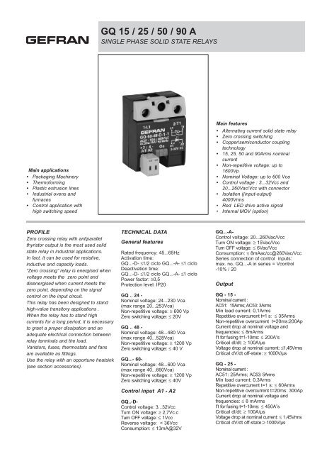
<strong>GQ</strong> 15 / 25 / 50 / 90 A<br />
SINGLE PHASE SOLID STATE RELAYS<br />
Main applications<br />
• Packaging Machinery<br />
• Thermoforming<br />
• Plastic extrusion lines<br />
• Industrial ovens and<br />
furnaces<br />
• Control application with<br />
high switching speed<br />
Main features<br />
• Alternating current solid state relay<br />
• Zero crossing switching<br />
• Copper/semiconductor coupling<br />
technology<br />
• 15, 25, 50 and 90Arms nominal<br />
current<br />
• Non-repetitive voltage: up to<br />
1600Vp<br />
• Nominal Voltage: up to 600 Vca<br />
• Control voltage : 3...32Vcc and<br />
20...260Vac/Vcc with connector<br />
• Isolation ((input-output)<br />
4000Vrms<br />
• Red LED drive active signal<br />
• Internal MOV (option)<br />
PROFILE<br />
Zero crossing relay with antiparallel<br />
thyristor output is the most used solid<br />
state relay in industrial applications.<br />
In fact, it can be used for resistive,<br />
inductive and capacity loads.<br />
“Zero crossing” relay is energised when<br />
voltage meets the zero point and<br />
disenergised when current meets the<br />
zero point, depending on the signal<br />
control on the input circuit.<br />
This relay has been designed to stand<br />
high-value transitory applications .<br />
When the relay has to stand high<br />
currents for a long period, it is necessary<br />
to grant a proper dissipation and an<br />
adequate electrical connection between<br />
relay terminals and the load.<br />
Varistors, fuses, thermostats and fans<br />
are available as fittings.<br />
Use the relay with an opportune heatsink<br />
(see section accessories).<br />
TECHNICAL DATA<br />
General features<br />
Rated frequency: 45...65Hz<br />
Activation time:<br />
<strong>GQ</strong>...-D- ≤1/2 ciclo <strong>GQ</strong>...-A- ≤1 ciclo<br />
Deactivation time:<br />
<strong>GQ</strong>...-D- ≤1/2 ciclo <strong>GQ</strong>...-A- ≤1 ciclo<br />
Power factor: ≥0,5<br />
Protection level: IP20<br />
<strong>GQ</strong> .. 24 -<br />
Nominal voltage: 24...230 Vca<br />
(max range 20...253Vca)<br />
Non-repetitive voltage: ≥ 600 Vp<br />
Zero switching voltage: ≤ 20V<br />
<strong>GQ</strong> .. 48 -<br />
Nominal voltage: 48...480 Vca<br />
(max range 40...528Vca)<br />
Non-repetitive voltage: ≥ 1200 Vp<br />
Zero switching voltage: ≤ 40 V<br />
<strong>GQ</strong>...- 60-<br />
Nominal voltage: 48...600 Vca<br />
(max range 40...660Vca)<br />
Non-repetitive voltage: ≥ 1200 Vp<br />
Zero switching voltage: ≤ 40V<br />
Control input A1 - A2<br />
<strong>GQ</strong>..-D-<br />
Control voltage: 3...32Vcc<br />
Turn ON voltage: ≥ 2,7Vc.c<br />
Turn OFF voltage: ≤ 1Vcc<br />
Reverse voltage: < 36Vcc<br />
Consumption: ≤ 13mA@32V<br />
<strong>GQ</strong>...-A-<br />
Control voltage: 20...260Vac/Vcc<br />
Turn ON voltage: ≥ 15Vac/Vcc<br />
Turn OFF voltage: ≤ 6Vac/Vcc<br />
Consumption: ≤ 8mAac/cc@260Vac/Vcc<br />
<strong>Series</strong> connection of control inputs:<br />
max. no. <strong>GQ</strong>...-A in series = Vcontrol<br />
-10% / 20<br />
Output<br />
<strong>GQ</strong> - 15 -<br />
Nominal current :<br />
AC51: 15Arms; AC53: 3Arms<br />
Min load current: 0,1Arms<br />
Repetitive overcurrent t=1 s: ≤ 35Arms<br />
Non-repetitive overcurrent t=20ms:200Ap<br />
Current drop at nominal voltage and<br />
frequencies: ≤ 8mArms<br />
I 2 t for fusing t=1-10ms: ≤ 200A 2 s<br />
Critical dl/dt: ≥ 100A/µs<br />
Voltage drop at nominal current: ≤1,45Vrms<br />
Critical dV/dt off-state: ≥ 1000V/µs<br />
<strong>GQ</strong> - 25 -<br />
Nominal current :<br />
AC51: 25Arms; AC53: 5Arms<br />
Min load current: 0,3Arms<br />
Repetitive overcurrent t=1 s: ≤ 60Arms<br />
Non-repetitive overcurrent t=20ms: 300Ap<br />
Current drop at nominal voltage and<br />
frequencies: ≤ 8 mArms<br />
I 2 t for fusing t=1-10ms: ≤ 450A 2 s<br />
Critical dl/dt: ≥ 100A/µs<br />
Voltage drop at nominal current: ≤ 1,45Vrms<br />
Critical dV/dt off-state:≥ 1000V/µs
<strong>GQ</strong> - 50 -<br />
Nominal current :<br />
AC51: 50Arms; AC53: 15Arms<br />
Min load current: 0,3Arms<br />
Repetitive overcurrent t=1 s: ≤ 125Arms<br />
Non-repetitive overcurrent t=20ms: 600Ap<br />
Current drop at nominal voltage and<br />
frequencies: ≤ 8mArms<br />
I 2 t for fusing t=1-10ms: ≤ 1800A 2 s<br />
Critical dl/dt: ≥ 100A/µs<br />
Voltage drop at nominal current: ≤1,35Vrms<br />
Critical dV/dt off-state: ≥ 1000V/µs<br />
<strong>GQ</strong> - 90 -<br />
Nominal current<br />
AC51: 90Arms; AC53: 20Arms<br />
Min load current: 0,5Arms<br />
Repetitive overcurrent t=1 s: ≤ 150Arms<br />
Non-repetitive overcurrent t=20ms: 1500 Ap<br />
Current drop at nominal voltage and<br />
frequencies: ≤ 10mArms<br />
I 2 t for fusing t=1-10ms: ≤ 11200A 2 s<br />
Critical dl/dt: ≥ 100A/µs<br />
Voltage drop at nominal current:≤ 1,35Vrms<br />
Critical dV/dt off-state: ≥ 1000V/µs<br />
(*) Only versions: <strong>GQ</strong>-XX-24-X-1<br />
<strong>GQ</strong>-XX-24-X-1<br />
Insulation<br />
Nominal insulation voltage<br />
Input/output: ≥ 4000 Vca<br />
Nominal insulation voltage<br />
Output/case: ≥ 2500 Vca<br />
Insulation resistance<br />
Input/output: ≥ 10 10 Ω<br />
Insulation resistance<br />
Output/case: ≥ 10 10 Ω<br />
Insulation capacity<br />
Input/Output: ≤ 8pF<br />
Insulation capacity<br />
Output/case: ≤ 100pF<br />
Ambient conditions<br />
Ambient temeparure: -25...+80°C<br />
Storage Temperature: -55...+100°C<br />
Maximum relative humidity: 50% a 40°C<br />
Maximum installation height: 2000 slm<br />
Pollution level : 3<br />
Thermal features<br />
<strong>GQ</strong> - 15 -<br />
<strong>GQ</strong> - 25 -<br />
Junction Temperature: ≤ 125°C<br />
Rth (temp.gradient) junction/case:<br />
≤ 1,25 K/W<br />
Rth (temp.gradient) junction/ambient:<br />
≤ 12 K/W<br />
<strong>GQ</strong> - 50 -<br />
Junction Temperature: ≤ 125°C<br />
Rth (temp.gradient) junction/case:<br />
≤ 0,65 K/W<br />
Rth (temp.gradient) junction/case:<br />
≤ 12 K/W<br />
<strong>GQ</strong> - 90 -<br />
Junction Temperature: ≤ 125°C<br />
Rth (temp.gradient) junction/case:<br />
≤ 0,3 K/W<br />
Rth (temp.gradient) junction/case:<br />
≤ 12 K/W<br />
Solid State Relay Dissipated Power<br />
Calculation<br />
Single phase state relay<br />
Pd <strong>GQ</strong> .. 15/25 = 1,45 * Irms [W]<br />
Pd <strong>GQ</strong> .. 50/90 = 1,35 * Irms [W]<br />
IRMS = single-phase load current<br />
Heatsink Thermal Resistance<br />
Calculation<br />
Rth = (90°C - max amb. T) / Pd<br />
where Pd = dissipated power<br />
Max. amb. T = max air temperature<br />
inside the electrical cabinet.<br />
Use a heatsink with thermal resistance<br />
inferior to the calculated one (Rth)<br />
Installation notes<br />
The device must be protected by a high<br />
speed fuse (accessory).<br />
Applications with power solid state relays<br />
must also have a switch to isolate the<br />
power line.<br />
Protect the solid state relay against overheating<br />
by using a heatsink (accessory).<br />
The heatsink must be sized according to<br />
room temperature and load current (see<br />
technical data).<br />
Heatsink installation procedure:<br />
spread 1 gram of thermoconductive silicone<br />
paste (we recommend DOW COR-<br />
NING 340) on the dissipative metal surfaces<br />
of the module.<br />
The surfaces must be clean and the thermoconductive<br />
paste must not contain<br />
any impurities. As alternative it is also<br />
possible to use the slide SIL-<strong>GQ</strong> available<br />
as accessory.<br />
Alternately tighten the two fastening<br />
screws until reaching a torque of<br />
0.4…0.6 Nm.<br />
Wait 5 minutes for any excess paste to<br />
run off.<br />
Alternately tighten the two fastening<br />
screws until reaching a torque of<br />
1.2…1.4 Nm.<br />
Attention<br />
The contact surface of the heatsink<br />
module may have a maximum planarity<br />
error of 0.1 mm and maximum roughness<br />
of 0.02 mm.<br />
The fastening holes on the heatsink must<br />
be threaded and countersunk.<br />
The heatsink must be grounded.<br />
DIMENSION<br />
Dimensions in mm, (inc)<br />
(*) See installation notes<br />
*Apply thermoconductive<br />
paste<br />
Raise the guard to access the<br />
fastening hole or the terminals
ELECTRICAL CONNECTIONS<br />
Connection of 3-phase load and 2-phase control<br />
Connection of single-phase load<br />
Heatsink (accessory)<br />
Connection of 3-phase load with closed/open triangle or star<br />
Digital<br />
output<br />
on/off<br />
Relay<br />
output<br />
TERMINALS AND LEADS: SPECIFICATIONS<br />
Power terminals<br />
1-L1 2-T2<br />
Terminal type<br />
Stripped<br />
wire<br />
Prod<br />
cable<br />
Prod cable<br />
with collar<br />
Fork or eyelet cable<br />
Locking torque 1x5...6mm<br />
screwdriver type ø 5...6mm<br />
2...2,4Nm<br />
screw (M4)<br />
contact area:<br />
(Lxp) 13x11mm<br />
1x2,5...6mm 2<br />
2x1,5...2,5mm 2<br />
2x2,5...6mm 2<br />
Stripped 11mm<br />
1x1,5...6mm 2<br />
2x1,5...2,5mm 2<br />
2x2,5...6mm 2<br />
1x1,5...10mm 2<br />
2x1,5...2,5mm 2<br />
2x2,5...6mm 2<br />
1x2,5...25mm 2<br />
slot 1x5...6mm<br />
cross ø 5...6mm<br />
2...2,4Nm<br />
Extractable 2 poles command terminals 3-A1 / 4-A2<br />
( see accessories)<br />
with self-locking<br />
spring<br />
MORS1<br />
1x0,2...2,5mm 2<br />
2x0,5...0,75mm 2 (#)<br />
stripped 10mm<br />
1x0,2...1,5mm 2<br />
2x0,2...0,75mm 2 (#)<br />
1x0,2...1,5mm 2<br />
-- --<br />
with slot 0,6x3,5mm<br />
for contact opening<br />
thrust<br />
with spring<br />
double connection<br />
MORS2<br />
2x(1x0,2...2,5mm 2 )<br />
2x(2x0,2...0,75mm 2 ) (#)<br />
stripped 10mm<br />
2x(1x0,25...2,5mm 2 )<br />
2x(2x0,25...0,75mm 2 ) (#)<br />
1x0,25...1,5mm 2<br />
-- --<br />
with slot 0,6x3,5mm<br />
for contact opening thrust<br />
(with flexible stripped cable)<br />
with screw<br />
(M3)<br />
MORS3<br />
1x0,25...2,5mm 2<br />
2x0,25...1mm 2 (#)<br />
stripped 7mm<br />
1x0,25...2,5mm 2<br />
2x0,25...1mm 2 (#)<br />
1x0,25...2,5mm 2<br />
2x0,25...1,5mm 2 (#)<br />
-- --<br />
with slot 0,6x3,5mm<br />
with cross ø 3...3,8mm<br />
0,5...0,6Nm<br />
(#) When inserting two leads in the same terminal they must have<br />
the same cross-section<br />
Note: The minimum and maximum sections shown refer to unipolar<br />
copper wires isolated in PVC.<br />
Note: Use an eye terminal to ground the heatsink.
FUSES/ FUSES HOLDER<br />
HIGH SPEED FUSES<br />
FUSE HOLDER<br />
Model<br />
Size<br />
I 2 T<br />
Code<br />
Format<br />
Model<br />
Code<br />
Dissipated<br />
power @ In<br />
Model<br />
Code<br />
Approval<br />
Max dissipated<br />
power<br />
Max continuative<br />
current<br />
<strong>GQ</strong>15...<br />
<strong>GQ</strong>25...<br />
<strong>GQ</strong>50...<br />
<strong>GQ</strong>90...<br />
16A<br />
150A 2 S<br />
25A<br />
390A 2 S<br />
25A<br />
375A 2 S<br />
50A<br />
1800A 2 S<br />
50A<br />
1600A 2 S<br />
80A<br />
6600A 2 S<br />
100A<br />
12500A 2 S<br />
FUS-016<br />
10x38<br />
FUS-025<br />
10x38<br />
FUS-026<br />
14x51<br />
FUS-051<br />
14x51<br />
FUS-050<br />
22x58<br />
FUS-080<br />
22x58<br />
FUS-100<br />
22X58<br />
FWC16A10F<br />
338470<br />
FWC25A10F<br />
338474<br />
FWC25A14F<br />
338130<br />
FWC50A14F<br />
338079<br />
FWC50A22F<br />
338127<br />
FWP80A22F<br />
338199<br />
FWP100A22F<br />
338478<br />
3,5W<br />
6W<br />
7W<br />
9W<br />
9,5W<br />
14W<br />
16W<br />
PFI-10x38<br />
337134<br />
UR 30A@690V<br />
PFI-14x51<br />
337503<br />
UR 50A@600V<br />
PFI-22x58<br />
337223<br />
UR 80A@600V<br />
3W<br />
5W<br />
9,5W<br />
13A<br />
13A<br />
18A<br />
27A<br />
50A<br />
50A<br />
60A<br />
HEATSINK/ THERMAL TESISTANCE<br />
SECTION CABLE<br />
Model<br />
GEFRAN HEATSINK<br />
(see accessories)<br />
THERMAL RESISTANCE<br />
Model<br />
Section<br />
<strong>GQ</strong>15...<br />
2,5mm 2<br />
<strong>GQ</strong>15...<br />
<strong>GQ</strong>25...<br />
DIS 25GD<br />
DIS 50G<br />
R th ≥ 2,8 K/W<br />
R th ≥ 0,83 K/W<br />
<strong>GQ</strong>25...<br />
<strong>GQ</strong>50...<br />
6mm 2<br />
12mm 2<br />
<strong>GQ</strong>50...<br />
<strong>GQ</strong>90...<br />
DIS 60G<br />
DIS 90G<br />
R th ≥ 0,66 K/W<br />
R th ≥ 0,56 K/W<br />
Data relating to 40°C ambient temperature, heatsink in vertical position<br />
with 15 cm of free air above and below.<br />
<strong>GQ</strong>90...<br />
25mm 2<br />
(**) Minimum allowed rated section based on the<br />
rated currents of the power solid state relays, for copper<br />
leads isolated in PVC in continuous use and at<br />
room temperature of 40°C, according to standards<br />
CEI 44-5, CEI 17-11, IEC 408 pursuant to standard<br />
EN60204-1.<br />
Power terminals in compliance with standard<br />
EN60947-1<br />
REFERENCE NORMS<br />
EMC Emission<br />
EN 60947-4-3<br />
Emissions conducted at radiofrequency Class A (Industrial devices)<br />
EN 60947-4-3<br />
Emissions irradiated at radiofrequency Class A (Industrial devices)<br />
EMC Immunity<br />
EN 61000-4-2 Electrostatic discharges 4kV by contact; 8 kV in air. Performance criterion 2.<br />
EN 61000-4-6 Electromagnetic field at radiofrequency Test level 3. Performance criterion 1<br />
0,15-80MHz<br />
EN 61000-4-3 3 Electromagnetic field at radiofrequency Test level 10V/m. Performance criterion 1.<br />
80-1000MHz<br />
EN 61000-4-4 Immunity to burst Test level 2kV/100 KHz. Performance criterion 2.<br />
EN 61000-4-5 Immunity to surge Test level: 2kV (Phase-ground); 1kV (Phase-phase).<br />
Performance criterion 2.<br />
Safety<br />
EN 61010-1<br />
Safety requirements
ORDER CODE<br />
<strong>GQ</strong><br />
MODEL<br />
<strong>GQ</strong><br />
NOMINAL CURRENT<br />
15ACArms 15<br />
25ACArms 25<br />
50ACArms 50<br />
90ACArms 90<br />
NOMINAL VOLTAGE<br />
230VCArms 24<br />
480VCArms 48<br />
600VCArms 60 (*)<br />
(*) Available only in versions <strong>GQ</strong>-XX-60-X-1-X<br />
(overloading protection always present)<br />
0<br />
1<br />
2<br />
3<br />
OVERVOLTAGE PROTECTION<br />
0 External<br />
1<br />
CONNECTORS<br />
Without connector<br />
(MORS1) Two-pin<br />
spring connector,<br />
enclosed<br />
(MORS2) Two-pin<br />
double spring<br />
connector, enclosed<br />
(MORS3) Two-pin<br />
screw connector,<br />
enclosed<br />
Internal MOV<br />
D<br />
A<br />
CONTROL VOLTAGE<br />
3...32Vc.c.<br />
20...260Vac/Vcc<br />
Please, contact GEFRAN sales people for the codes availability.<br />
GEFRAN spa reserves the right to make any kind of design or functional modification at any moment without prior notice<br />
•WARNINGS<br />
WARNING: this symbol indicates danger.<br />
Before installation, please read the following advices:<br />
• follow the indications of the manual scrupulously when making the connections to the instrument.<br />
• use a cable that is suitable for the ratings of voltage and current indicated in the technical specifications.<br />
• if the instrument is used in applications where there is risk of injury to persons and damage to machines or materials, it is essential that it is used with<br />
an auxiliary alarm device.<br />
It is advisable to verify frequently that the alarm device is functional even during the normal operation of the equipment.<br />
• The instrument must NOT be used in environments where there could be the presence of dangerous atmospheres (inflammable or explosive).<br />
• During continuous operation, the heatsink may reach 100°C and remain at a high temperature due to thermal inertia even after the device is switched<br />
off. Therefore, DO NOT touch the heat sink or the electrical wires.<br />
• do not operate on the power circuit untless the main supply is disconnected.<br />
• DO NOT open the cover if device is “ON”!<br />
(use the holes in the cover for eventual re-calibration).<br />
Installation:<br />
• connect the device to the ground using the proper ground terminal.<br />
• the power supply wiring must be kept separate from that of inputs and outputs of the instrument; always check that the supply voltage corresponds to<br />
that indicated on the instrument cover.<br />
• evitare la polvere, l’ umidità, i gas corrosivi, le fonti di calore.<br />
• keep away from dust, humidity, corrosive gases and heat sources.<br />
• The connection cable must be shorter than 3 meters if the current transformer is used.<br />
Maintenance: Check the correct operation of the cooling fans at regular intervals; clean the ventilation air filters of the installation at regular intervals.<br />
• Repairs must be performed only by specialized or appropriately trained personnel. Cut off power to the device before accessing internal parts.<br />
• Do not clean the box with solvents derived from hydrocarbons (trichloroethylene, gasoline, etc.). Using such solvents will compromise the mechanical<br />
reliability of the device. To clean external plastic parts, use a clean cloth wet with ethyl alcohol or water.<br />
Technical service : GEFRAN has a technical service department. Defects caused by use not conforming to the instructions are excluded from the warranty.<br />
In conformity to ECC 2004/108/CE and 2006/95/CE and following modification with reference to standards:<br />
EN 60947-4-3 (Low voltage equipment – Contactors and starters for different motor loads)<br />
EN 60947-4-2 (Low voltage equipment - AC Semiconductor starters and contactors)<br />
®<br />
In Conformity with UL508<br />
GEFRAN spa<br />
via Sebina, 74 - 25050 Provaglio d’Iseo (BS)<br />
Tel. +39 030 9888.1 - fax +39 030 9839063 Internet: http://www.gefran.com<br />
DTS_<strong>GQ</strong>_1108_ENG