MMSR 3-Knob 3-Band Preamp - Bass Pickups | Preamps
MMSR 3-Knob 3-Band Preamp - Bass Pickups | Preamps
MMSR 3-Knob 3-Band Preamp - Bass Pickups | Preamps

You also want an ePaper? Increase the reach of your titles
YUMPU automatically turns print PDFs into web optimized ePapers that Google loves.
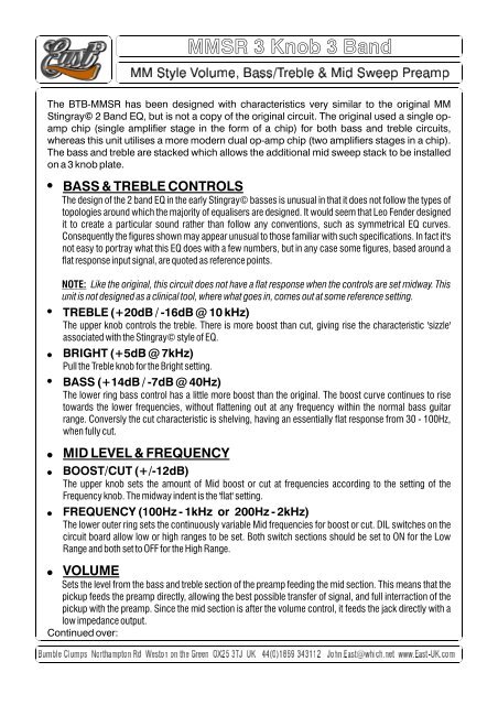
<strong>MMSR</strong> 3<strong>Knob</strong> 3<strong>Band</strong><br />
The BTB-<strong>MMSR</strong> has been designed with characteristics very similar to the original MM<br />
Stingray©<br />
2<strong>Band</strong>EQ,butisnotacopyoftheoriginalcircuit.Theoriginalusedasingleopamp<br />
chip (single amplifier stage in the form of achip) for both bass and treble circuits,<br />
whereasthisunitutilisesamoremoderndualop-ampchip(twoamplifiersstagesinachip).<br />
Thebassandtreblearestackedwhichallowstheadditionalmidsweepstacktobeinstalled<br />
ona3knobplate.<br />
!<br />
!<br />
!<br />
!<br />
!<br />
!<br />
!<br />
!<br />
BASS&TREBLECONTROLS<br />
Thedesignofthe2bandEQintheearlyStingray©bassesisunusualinthatitdoesnotfollowthetypesof<br />
topologiesaroundwhichthemajorityofequalisersaredesigned.ItwouldseemthatLeoFenderdesigned<br />
it to create aparticular sound rather than follow any conventions, such as symmetrical EQ curves.<br />
Consequentlythefiguresshownmayappearunusualtothosefamiliarwithsuchspecifications.Infactit's<br />
not easy to portray what this EQdoes with afew numbers, butin any case some figures, based arounda<br />
flatresponseinputsignal,arequotedasreferencepoints.<br />
NOTE: Liketheoriginal,thiscircuitdoesnothaveaflatresponsewhenthecontrolsaresetmidway.This<br />
unitisnotdesignedasaclinicaltool,wherewhatgoesin,comesoutatsomereferencesetting.<br />
TREBLE(+20dB/-16dB@10kHz)<br />
The upper knob controls the treble. There is more boost than cut, giving rise the characteristic 'sizzle'<br />
associatedwiththeStingray©styleofEQ.<br />
BRIGHT(+5dB@7kHz)<br />
PulltheTrebleknobfortheBrightsetting.<br />
BASS(+14dB/-7dB@40Hz)<br />
The lower ring bass control has alittle more boost than the original. The boost curve continues to rise<br />
towards the lower frequencies, without flattening out at any frequency within the normal bass guitar<br />
range. Conversly the cut characteristic is shelving, having an essentially flat response from 30 -100Hz,<br />
whenfullycut.<br />
MIDLEVEL&FREQUENCY<br />
BOOST/CUT(+/-12dB)<br />
The upper knob sets the amount of Mid boost or cut at frequencies according to the setting of the<br />
Frequencyknob.Themidwayindentisthe'flat'setting.<br />
FREQUENCY(100Hz-1kHz or 200Hz-2kHz)<br />
The lower outer ring sets the continuously variable Mid frequencies for boost or cut. DIL switches on the<br />
circuit board allow low or high ranges to be set. Both switch sections should be set to ON for the Low<br />
RangeandbothsettoOFFfortheHighRange.<br />
VOLUME<br />
Setsthelevelfromthebassandtreblesectionofthepreampfeedingthemidsection.Thismeansthatthe<br />
pickup feeds the preamp directly,allowing the best possible transfer of signal, and full interraction of the<br />
pickup with the preamp. Since the mid section is after the volume control, it feeds the jack directly with a<br />
lowimpedanceoutput.<br />
Continuedover:
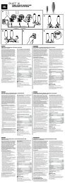
MID SWEEP 01<br />
TheMIDSWEEP01isastand-alonemidcontrolwhichcanbeusedonitsownorcascadedin<br />
conjunctionwithothermodules,includingadditionalMIDSWEEP01s.Thesweepfrequency<br />
bandisswitchable,viaDILswitchesonthecircuitboard,betweentwooverlappingranges.<br />
! MIDLEVEL&FREQUENCY<br />
! BOOST/CUT(+/-12dB)<br />
!<br />
!<br />
The upper knob sets the amount of Mid boost or cut at frequencies according to the setting of the<br />
Frequencyknob.Themidwayindentisthe'flat'setting.<br />
FREQUENCY(100Hz-1kHz or 200Hz-2kHz)<br />
The lower outer ring sets the continuously variable Mid frequencies for boost or cut. DIL switches on the<br />
circuit board allow low or high ranges to be set. Both switch sections should be set to ON for the Low<br />
RangeandbothsettoOFFfortheHighRange.<br />
POWER<br />
Thisunitcanbepoweredfrom9-18VoltsDC.<br />
HIGH<br />
LOW<br />
DIL<br />
SWITCH<br />
Set Both<br />
MID FREQUENCY RANGE<br />
LINKED<br />
ON PCB<br />
9-18V +VE<br />
OUTPUT<br />
GND<br />
INPUT<br />
Hot<br />
Cold
!<br />
!<br />
POWER<br />
Thisunitcanbepoweredfrom9-18VoltsDC.<br />
INSTALLATION<br />
!<br />
!<br />
!<br />
!<br />
!<br />
!<br />
!<br />
!<br />
!<br />
Ifnecessary,removetheoldelectronicsleavingthepickupwires,andanyothers,suchasgroundand<br />
batterywires,withplentyoflength.<br />
The single pot is the Volume and its thread is 7.0mm size. Fit into its hole leaving the rubber spacer<br />
ringsinplaceiftheholesaretheoriginallargersize.Tightenonceinplace.<br />
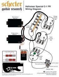
Mountthe bass/treble circuitboard inthe next hole,which isthepositionfor the treble in theoriginal3<br />
knob plate. (See BTB-MM diagram in order to recognise the bass/treble circuit board, which has two<br />
barepinsatoneend,forthepickupinput)<br />
Mountthemidsweepstackintheholeusedforthebasscontrolintheoriginal3knobplate.<br />
Mountthepre-wiredjackintothesameholeastheoriginaljack.<br />
Connectthepickupswirestothebass/treblecircuitboard,accordingthetheBTB-MMdiagram.<br />
Abatteryclipisprovidedwiththepreampallowingittobepowereddirectly.Butmostbasseswillhave<br />
aseparatebatterycompartment.Inwhichcase,cutofthebatteryclipandjointheredandblackwires<br />
from the the preamp tothose in the bass. Before joiningthe wires, slip the heatshrinksleevesover the<br />
wires.Afterthejointshavebeenmade,thesleevingshouldbeslidoverthejointsandheatedwithahot<br />
soldering iron, or other localised heat source, held in close proximity.(The heatshrink sleeves can be<br />
foundthreadedontheblackgroundwire)<br />
Connect the black ground wire from the jack to any ground wires in the bass, such as the one to the<br />
bridge.<br />
Onceallisproventobeworkingcorrectly,fittheknobstotheirappropriateshafts,andrefitplate.