Influence of strain on semiconductor thin film epitaxy - Fitzgerald ...
Influence of strain on semiconductor thin film epitaxy - Fitzgerald ...
Influence of strain on semiconductor thin film epitaxy - Fitzgerald ...

Create successful ePaper yourself
Turn your PDF publications into a flip-book with our unique Google optimized e-Paper software.
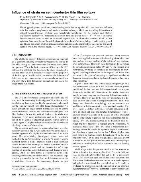
<str<strong>on</strong>g>Influence</str<strong>on</strong>g> <str<strong>on</strong>g>of</str<strong>on</strong>g> <str<strong>on</strong>g>strain</str<strong>on</strong>g> <strong>on</strong> semic<strong>on</strong>ductor <strong>thin</strong> <strong>film</strong> <strong>epitaxy</strong><br />
E. A. <strong>Fitzgerald</strong>, a) S. B. Samavedam, Y. H. Xie, b) and L. M. Giovane<br />
Department <str<strong>on</strong>g>of</str<strong>on</strong>g> Materials Science and Engineering, MIT, Cambridge, Massachusetts 02139<br />
Received 2 October 1996; accepted 24 March 1997<br />
Under typical growth c<strong>on</strong>diti<strong>on</strong>s, <str<strong>on</strong>g>strain</str<strong>on</strong>g> levels greater than or equal to 10 4 are shown to influence<br />
<strong>thin</strong> <strong>film</strong> surface morphology and <str<strong>on</strong>g>strain</str<strong>on</strong>g> relaxati<strong>on</strong> pathways. Misfit and threading dislocati<strong>on</strong>s in<br />
relaxed heterostructures produce l<strong>on</strong>g wavelength undulati<strong>on</strong>s <strong>on</strong> the surface and shallow<br />
depressi<strong>on</strong>s, respectively. Threading dislocati<strong>on</strong> densities greater than 10 5 –10 6 cm 2 in relaxed<br />
heterostructures must be due to increased impediments to dislocati<strong>on</strong> moti<strong>on</strong>, which in turn<br />
originate from the effect <str<strong>on</strong>g>of</str<strong>on</strong>g> the misfit dislocati<strong>on</strong>s <strong>on</strong> the surface morphology. Under typical growth<br />
c<strong>on</strong>diti<strong>on</strong>s, the origin <str<strong>on</strong>g>of</str<strong>on</strong>g> <str<strong>on</strong>g>strain</str<strong>on</strong>g>-induced surface features can be identified by recognizing the length<br />
scale at which the features occur. © 1997 American Vacuum Society. S0734-21019711403-8<br />
I. INTRODUCTION<br />
The ability to employ different semic<strong>on</strong>ductor materials<br />
<strong>on</strong> a comm<strong>on</strong> substrate for many applicati<strong>on</strong>s is limited by<br />
the wide variety <str<strong>on</strong>g>of</str<strong>on</strong>g> lattice c<strong>on</strong>stants that these semic<strong>on</strong>ductors<br />
possess. When the lattice c<strong>on</strong>stant differs by <strong>on</strong>ly 10 4<br />
between the substrate and <strong>thin</strong> <strong>film</strong>, the <str<strong>on</strong>g>strain</str<strong>on</strong>g> introduced in<br />
the <strong>thin</strong> <strong>film</strong> can have pr<strong>on</strong>ounced effects <strong>on</strong> the properties<br />
<str<strong>on</strong>g>of</str<strong>on</strong>g> device layers. In this article, we review the influence <str<strong>on</strong>g>of</str<strong>on</strong>g><br />
defect <str<strong>on</strong>g>strain</str<strong>on</strong>g>s and lattice <str<strong>on</strong>g>strain</str<strong>on</strong>g>s <strong>on</strong> semic<strong>on</strong>ductor <strong>thin</strong> <strong>film</strong>s,<br />
and also show that deleterious interacti<strong>on</strong>s can occur between<br />
these two <str<strong>on</strong>g>strain</str<strong>on</strong>g>s.<br />
II. THE SIGNIFICANCE OF THE GeSi SYSTEM<br />
The GeSi alloy system is a completely miscible alloy system,<br />
ideal for decreasing the band gap <str<strong>on</strong>g>of</str<strong>on</strong>g> Si, which is useful<br />
in fabricating heterojuncti<strong>on</strong> bipolar transistors 1 and extending<br />
the l<strong>on</strong>g wavelength limit <str<strong>on</strong>g>of</str<strong>on</strong>g> Si-based photodetectors. 2 In<br />
these applicati<strong>on</strong>s, slight lattice mismatches can be accommodated<br />
between the <strong>film</strong> and substrate by keeping the GeSi<br />
<strong>film</strong> thickness below the critical thickness for dislocati<strong>on</strong><br />
formati<strong>on</strong>. 3,4 For many applicati<strong>on</strong>s such as III–V integrati<strong>on</strong><br />
<strong>on</strong> Si the goal is to create high quality, relaxed semic<strong>on</strong>ductor<br />
layers. Complete relaxati<strong>on</strong> requires the introducti<strong>on</strong><br />
<str<strong>on</strong>g>of</str<strong>on</strong>g> a large number <str<strong>on</strong>g>of</str<strong>on</strong>g> dislocati<strong>on</strong>s.<br />
The relaxati<strong>on</strong> pathways for mismatched <strong>film</strong>s are schematically<br />
drawn in Fig. 1. One method shown in the figure is<br />
the direct growth <str<strong>on</strong>g>of</str<strong>on</strong>g> a highly mismatched material <strong>on</strong> a substrate.<br />
The most widely investigated system using this<br />
method is the GaAs/Si system, 5 in which 4% <str<strong>on</strong>g>strain</str<strong>on</strong>g> is accommodated<br />
across a single interface. Such a high mismatch<br />
creates unc<strong>on</strong>trolled pathways to lattice relaxati<strong>on</strong>, such as<br />
three-dimensi<strong>on</strong>al growth and the introducti<strong>on</strong> <str<strong>on</strong>g>of</str<strong>on</strong>g> a large<br />
number <str<strong>on</strong>g>of</str<strong>on</strong>g> immobile edge dislocati<strong>on</strong>s and threading dislocati<strong>on</strong>s.<br />
After the <strong>film</strong> forms a c<strong>on</strong>tinuous layer, some<br />
threading dislocati<strong>on</strong>s annihilate due to the extremely large<br />
number generated at the interface, so dislocati<strong>on</strong> interacti<strong>on</strong><br />
is probable. However, the remaining density is near<br />
a Electr<strong>on</strong>ic mail: eafitz@mit.edu<br />
b Present address: Lucent Technologies, Murray Hill, NJ 07974.<br />
10 8 cm 2 or higher for practical thickness. Many methods<br />
have been applied to reduce this threading dislocati<strong>on</strong> density,<br />
such as thermal cycling <str<strong>on</strong>g>of</str<strong>on</strong>g> the substrate 6 and <str<strong>on</strong>g>strain</str<strong>on</strong>g>edlayer<br />
superlattices. 7 However, these techniques do not reduce<br />
the threading dislocati<strong>on</strong> below 10 8 cm 2 . The <str<strong>on</strong>g>strain</str<strong>on</strong>g>ed layer<br />
superlattice, proposed to eliminate all dislocati<strong>on</strong>s by moving<br />
the threading dislocati<strong>on</strong>s to the edge <str<strong>on</strong>g>of</str<strong>on</strong>g> the wafer, cannot<br />
achieve the goal <str<strong>on</strong>g>of</str<strong>on</strong>g> removing a significant number <str<strong>on</strong>g>of</str<strong>on</strong>g><br />
threading dislocati<strong>on</strong>s due to the limited <str<strong>on</strong>g>strain</str<strong>on</strong>g> available <strong>on</strong> a<br />
large substrate. 8<br />
Figure 1 also shows the typical defect morphology for a<br />
low mismatched system 1.5% for most comm<strong>on</strong> growth<br />
c<strong>on</strong>diti<strong>on</strong>s. In this case, the dislocati<strong>on</strong>s introduced are predominately<br />
mobile 60° dislocati<strong>on</strong>s, the misfit dislocati<strong>on</strong><br />
lengths are very l<strong>on</strong>g, and the threading dislocati<strong>on</strong> density is<br />
very low. However, due to the very low mismatch, it is difficult<br />
to drive the system to complete relaxati<strong>on</strong>. Thus, even<br />
though the dislocati<strong>on</strong> morphology is more attractive, the<br />
small jump in lattice c<strong>on</strong>stant is not a practical soluti<strong>on</strong>. Figure<br />
1 shows a distinct difference between relaxati<strong>on</strong> pathways<br />
in small and large mismatched hetero<strong>epitaxy</strong>. The relaxati<strong>on</strong><br />
pathway depends <strong>on</strong> the degree <str<strong>on</strong>g>of</str<strong>on</strong>g> lattice mismatch<br />
and the temperature <str<strong>on</strong>g>of</str<strong>on</strong>g> growth. For many semic<strong>on</strong>ductor materials,<br />
1.5%–2% mismatch <str<strong>on</strong>g>strain</str<strong>on</strong>g> is the transiti<strong>on</strong> point between<br />
the two pathways at typical growth c<strong>on</strong>diti<strong>on</strong>s. At<br />
mismatch <str<strong>on</strong>g>strain</str<strong>on</strong>g>s near 1.5%–2% <str<strong>on</strong>g>strain</str<strong>on</strong>g>, a transiti<strong>on</strong>al morphology<br />
occurs in which the epitaxial layer is c<strong>on</strong>tinuous,<br />
but develops a ripple <strong>on</strong> the surface. 9 These ripples have<br />
been shown to nucleate misfit dislocati<strong>on</strong>s when the layer<br />
begins to relax. 10 In the case <str<strong>on</strong>g>of</str<strong>on</strong>g> liquid phase epitaxial growth<br />
<str<strong>on</strong>g>of</str<strong>on</strong>g> GeSi <strong>on</strong> Si, the growth temperatures are extremely high,<br />
and even at relatively low lattice mismatch, <strong>on</strong>e can develop<br />
surface ripples. 11<br />
GeSi alloys <str<strong>on</strong>g>of</str<strong>on</strong>g>fer the perfect soluti<strong>on</strong> to the problem <str<strong>on</strong>g>of</str<strong>on</strong>g><br />
lattice relaxati<strong>on</strong> for many applicati<strong>on</strong>s. For both GeSi devices<br />
<strong>on</strong> relaxed GeSi/Si Ref. 12 and for III–V integrati<strong>on</strong><br />
<strong>on</strong> Si, GeSi alloys can span the desired lattice c<strong>on</strong>stants. For<br />
this reas<strong>on</strong>, GeSi relaxati<strong>on</strong> was studied as a model system,<br />
and indeed it was found that relaxed alloys <strong>on</strong> Si could be<br />
produced by employing graded-compositi<strong>on</strong> layers grown at<br />
high temperatures 13 900 °C compared to c<strong>on</strong>venti<strong>on</strong>al GeSi<br />
1048 J. Vac. Sci. Technol. A 15(3), May/Jun 1997 0734-2101/97/15(3)/1048/9/$10.00 ©1997 American Vacuum Society 1048
1049 <strong>Fitzgerald</strong> et al.: <str<strong>on</strong>g>Influence</str<strong>on</strong>g> <str<strong>on</strong>g>of</str<strong>on</strong>g> <str<strong>on</strong>g>strain</str<strong>on</strong>g> <strong>on</strong> semic<strong>on</strong>ductor <strong>thin</strong> <strong>film</strong> <strong>epitaxy</strong> 1049<br />
FIG. 1. Schematic showing typical defect morphology in low mismatched<br />
and high mismatched hetero<strong>epitaxy</strong>. In the low mismatch case the epilayer<br />
relaxes typically by nucleating l<strong>on</strong>g 60° misfit dislocati<strong>on</strong>s. Under a high<br />
lattice mismatch the epilayer will tend to nucleate in form <str<strong>on</strong>g>of</str<strong>on</strong>g> 3-D islands,<br />
which subsequently coalesce. The relaxati<strong>on</strong> is predominantly by formati<strong>on</strong><br />
<str<strong>on</strong>g>of</str<strong>on</strong>g> edge dislocati<strong>on</strong>s.<br />
growth 550 °C. Essentially by creating a series <str<strong>on</strong>g>of</str<strong>on</strong>g> low mismatched<br />
interfaces at high temperature, it is possible to encourage<br />
dislocati<strong>on</strong> propagati<strong>on</strong> and minimize dislocati<strong>on</strong><br />
nucleati<strong>on</strong>, resulting in complete relaxati<strong>on</strong> <str<strong>on</strong>g>of</str<strong>on</strong>g> GeSi alloys <strong>on</strong><br />
Si with threading dislocati<strong>on</strong> densities <strong>on</strong> the order <str<strong>on</strong>g>of</str<strong>on</strong>g><br />
10 5 –10 6 cm 2 . 14 Thus, the surface during the graded layer<br />
growth is always in the low mismatch regime discussed<br />
above, allowing l<strong>on</strong>g misfit lengths in the relaxed graded<br />
layer.<br />
The remaining porti<strong>on</strong> <str<strong>on</strong>g>of</str<strong>on</strong>g> this article c<strong>on</strong>centrates <strong>on</strong> the<br />
effect <str<strong>on</strong>g>of</str<strong>on</strong>g> defect <str<strong>on</strong>g>strain</str<strong>on</strong>g> in these graded relaxed buffer layers<br />
and the effect <str<strong>on</strong>g>of</str<strong>on</strong>g> <str<strong>on</strong>g>strain</str<strong>on</strong>g> <strong>on</strong> layers grown <strong>on</strong> these buffers.<br />
Graded buffers <str<strong>on</strong>g>of</str<strong>on</strong>g>fer the best pathway to high quality, relaxed<br />
layers with significant lattice mismatch, and the effects<br />
<str<strong>on</strong>g>of</str<strong>on</strong>g> <str<strong>on</strong>g>strain</str<strong>on</strong>g> in these structures is critical in evaluating their potential<br />
for different applicati<strong>on</strong>s. We begin by discussing the<br />
effect <str<strong>on</strong>g>of</str<strong>on</strong>g> <str<strong>on</strong>g>strain</str<strong>on</strong>g> from the defects in the relaxed layers, and<br />
then discuss the effect <str<strong>on</strong>g>of</str<strong>on</strong>g> mismatch <str<strong>on</strong>g>strain</str<strong>on</strong>g> <strong>on</strong> device layers<br />
grown <strong>on</strong> these relaxed buffers.<br />
A. Defect <str<strong>on</strong>g>strain</str<strong>on</strong>g><br />
In relaxed graded structures grown under low mismatch<br />
<str<strong>on</strong>g>strain</str<strong>on</strong>g> c<strong>on</strong>diti<strong>on</strong>s, it has l<strong>on</strong>g been known that a cross-hatch<br />
surface morphology Fig. 2 occurs when growth is performed<br />
<strong>on</strong> 001 oriented substrates. Although the presence<br />
<str<strong>on</strong>g>of</str<strong>on</strong>g> the cross-hatch pattern has been associated with dislocati<strong>on</strong><br />
lines at the mismatch interface, the exact correlati<strong>on</strong><br />
between the dislocati<strong>on</strong> lines and surface morphology is usually<br />
absent. It has been shown that the cross-hatch pattern in<br />
low-mismatch, heavily relaxed layers correlates with misfit<br />
FIG. 2. An AFM image <str<strong>on</strong>g>of</str<strong>on</strong>g> a relaxed graded GeSi structure grown <strong>on</strong> Si001<br />
showing the cross-hatch surface morphology.<br />
dislocati<strong>on</strong> groups at the heterointerface 15 and that the crosshatch<br />
pattern is a resp<strong>on</strong>se <str<strong>on</strong>g>of</str<strong>on</strong>g> the epitaxial surface to the<br />
<str<strong>on</strong>g>strain</str<strong>on</strong>g> fields originating from the buried misfit dislocati<strong>on</strong>s. 14<br />
In graded layers, the distance <str<strong>on</strong>g>of</str<strong>on</strong>g> the surface from the buried<br />
misfit dislocati<strong>on</strong>s is c<strong>on</strong>trolled by the grading rate, i.e., the<br />
amount <str<strong>on</strong>g>of</str<strong>on</strong>g> mismatch introduced per thickness. A larger grading<br />
rate reduces the thickness <str<strong>on</strong>g>of</str<strong>on</strong>g> the <str<strong>on</strong>g>strain</str<strong>on</strong>g>ed layer which is<br />
present at the surface throughout graded layer growth, bringing<br />
the surface closer to the buried misfit dislocati<strong>on</strong>s. Thus,<br />
if the total relaxati<strong>on</strong> is equal, a comparis<strong>on</strong> <str<strong>on</strong>g>of</str<strong>on</strong>g> the surface <str<strong>on</strong>g>of</str<strong>on</strong>g><br />
relaxed graded GeSi layers with different grading rates will<br />
reveal the effect <str<strong>on</strong>g>of</str<strong>on</strong>g> the buried misfit dislocati<strong>on</strong> <str<strong>on</strong>g>strain</str<strong>on</strong>g> fields.<br />
Indeed, the surface morphology degrades and the root-meansquared<br />
rms roughness increases.<br />
To c<strong>on</strong>nect the effect <str<strong>on</strong>g>of</str<strong>on</strong>g> dislocati<strong>on</strong> <str<strong>on</strong>g>strain</str<strong>on</strong>g> fields to the<br />
surface morphology, two models are needed: a model which<br />
determines the magnitude <str<strong>on</strong>g>of</str<strong>on</strong>g> the defect <str<strong>on</strong>g>strain</str<strong>on</strong>g> fields at the<br />
surface, and a model which describes the resp<strong>on</strong>se <str<strong>on</strong>g>of</str<strong>on</strong>g> that<br />
surface to the <str<strong>on</strong>g>strain</str<strong>on</strong>g> fields. The first can be accomplished by<br />
using c<strong>on</strong>tinuum elastic theory and known expressi<strong>on</strong>s for<br />
dislocati<strong>on</strong> stress fields, and the latter can be achieved with<br />
an equilibrium calculati<strong>on</strong> which balances <str<strong>on</strong>g>strain</str<strong>on</strong>g> energy with<br />
surface energy.<br />
The stress fields from a 60° also called a mixed dislocati<strong>on</strong><br />
can be thought <str<strong>on</strong>g>of</str<strong>on</strong>g> as a mix between the stress fields <str<strong>on</strong>g>of</str<strong>on</strong>g><br />
two edge dislocati<strong>on</strong>s and those <str<strong>on</strong>g>of</str<strong>on</strong>g> a screw dislocati<strong>on</strong>. Thus,<br />
a mixed dislocati<strong>on</strong> produces a completely n<strong>on</strong>zero stress<br />
tensor at every point in the material around the dislocati<strong>on</strong>:<br />
Dy3x 2 y 2 <br />
Dxx 2 y 2 <br />
b s y<br />
4s<br />
Dxx 2 y 2 <br />
Dyx 2 y 2 <br />
b s x<br />
4s<br />
b s y<br />
4s<br />
b s x<br />
4s<br />
2Gb s y<br />
21sDy3x 2 y 2 Dxx 2 y 2 0<br />
Dxx 2 y 2 Dyx 2 y 2 0<br />
2Gb s y<br />
0 0<br />
21s,<br />
JVST A - Vacuum, Surfaces, and Films
1050 <strong>Fitzgerald</strong> et al.: <str<strong>on</strong>g>Influence</str<strong>on</strong>g> <str<strong>on</strong>g>of</str<strong>on</strong>g> <str<strong>on</strong>g>strain</str<strong>on</strong>g> <strong>on</strong> semic<strong>on</strong>ductor <strong>thin</strong> <strong>film</strong> <strong>epitaxy</strong> 1050<br />
D Gb <br />
e<br />
, s x 2 y 2 ,<br />
s 2<br />
where G is the shear modulus, b e is the magnitude <str<strong>on</strong>g>of</str<strong>on</strong>g> the<br />
edge comp<strong>on</strong>ent <str<strong>on</strong>g>of</str<strong>on</strong>g> the Burgers vector in the plane <str<strong>on</strong>g>of</str<strong>on</strong>g> the<br />
mismatch interface <str<strong>on</strong>g>strain</str<strong>on</strong>g> relief comp<strong>on</strong>ent, b e is the magnitude<br />
<str<strong>on</strong>g>of</str<strong>on</strong>g> the edge comp<strong>on</strong>ent <str<strong>on</strong>g>of</str<strong>on</strong>g> the Burgers vector in the<br />
plane perpendicular to the interface tilt comp<strong>on</strong>ent, b s is<br />
the magnitude <str<strong>on</strong>g>of</str<strong>on</strong>g> the screw comp<strong>on</strong>ent <str<strong>on</strong>g>of</str<strong>on</strong>g> the Burgers vector<br />
al<strong>on</strong>g the z directi<strong>on</strong>, and the dislocati<strong>on</strong> is assumed to be<br />
lying al<strong>on</strong>g the z axis. The stress tensor <strong>on</strong> the right-hand<br />
side is in a coordinate system that is rotated 90° with respect<br />
to the stress tensor <strong>on</strong> the left-hand side. The x and z directi<strong>on</strong>s<br />
are al<strong>on</strong>g the misfit interface, whereas the y directi<strong>on</strong> is<br />
perpendicular to the interface in the case <str<strong>on</strong>g>of</str<strong>on</strong>g> the left-hand<br />
expressi<strong>on</strong>.<br />
To determine the effect <str<strong>on</strong>g>of</str<strong>on</strong>g> a randomly located array <str<strong>on</strong>g>of</str<strong>on</strong>g><br />
misfit dislocati<strong>on</strong>s, we need to calculate the total stress tensor<br />
at a point by summing the stress fields from all the dislocati<strong>on</strong>s<br />
acting <strong>on</strong> that point. Although translating the tensors<br />
into correct coordinate systems is tedious, the effect <str<strong>on</strong>g>of</str<strong>on</strong>g><br />
each <str<strong>on</strong>g>of</str<strong>on</strong>g> these dislocati<strong>on</strong>s <strong>on</strong> a point in the material can be<br />
determined. The total stress tensor then can be rotated into<br />
the coordinate system <str<strong>on</strong>g>of</str<strong>on</strong>g> the elastic c<strong>on</strong>stants, C ij , and the<br />
<str<strong>on</strong>g>strain</str<strong>on</strong>g> fields can be solved using i C ij j . Thus, we can<br />
establish a picture <str<strong>on</strong>g>of</str<strong>on</strong>g> the <str<strong>on</strong>g>strain</str<strong>on</strong>g>s in the material by solving the<br />
equati<strong>on</strong> at each point in the material, in our case the material<br />
above the buried misfit array. Figure 3 is a c<strong>on</strong>tour plot<br />
<str<strong>on</strong>g>of</str<strong>on</strong>g> the <str<strong>on</strong>g>strain</str<strong>on</strong>g> fields above a low-mismatched graded layer, in<br />
which the dislocati<strong>on</strong>s are randomly placed in the first 0.1<br />
m cross-secti<strong>on</strong> view. The c<strong>on</strong>tours are separated by<br />
10 4 <str<strong>on</strong>g>strain</str<strong>on</strong>g>, and the <str<strong>on</strong>g>strain</str<strong>on</strong>g> in the 001 directi<strong>on</strong> is plotted<br />
( 33 ). Although we chose this particular part <str<strong>on</strong>g>of</str<strong>on</strong>g> the <str<strong>on</strong>g>strain</str<strong>on</strong>g><br />
tensor, it should be remembered that all other elements are<br />
n<strong>on</strong>zero as well. Even at 2 m from the surface, there are<br />
still varying <str<strong>on</strong>g>strain</str<strong>on</strong>g> fields <strong>on</strong> the order <str<strong>on</strong>g>of</str<strong>on</strong>g> 10 4 over distances<br />
<str<strong>on</strong>g>of</str<strong>on</strong>g> micr<strong>on</strong>s. This calculati<strong>on</strong> is encouraging since this wavelength<br />
is approximately what we expect for the cross-hatch<br />
pattern.<br />
In the calculati<strong>on</strong> for Fig. 3, it is important to menti<strong>on</strong> that<br />
the effects <str<strong>on</strong>g>of</str<strong>on</strong>g> a surface are not c<strong>on</strong>sidered, i.e., the <str<strong>on</strong>g>strain</str<strong>on</strong>g> and<br />
stress fields are assumed to be in an infinite solid. To be<br />
more precise, the zero-stress boundary c<strong>on</strong>diti<strong>on</strong> at the surface<br />
must be included. This correcti<strong>on</strong> leads to a more rapid<br />
decay <str<strong>on</strong>g>of</str<strong>on</strong>g> the stress towards the surface. However, the ‘‘no<br />
surface’’ approximati<strong>on</strong> is valid to the degree that we c<strong>on</strong>sider<br />
structures in which the surface is far from the dislocati<strong>on</strong>s,<br />
because the <str<strong>on</strong>g>strain</str<strong>on</strong>g> pr<str<strong>on</strong>g>of</str<strong>on</strong>g>iles will not change significantly<br />
for such low values <str<strong>on</strong>g>of</str<strong>on</strong>g> stress.<br />
As menti<strong>on</strong>ed above, the sec<strong>on</strong>d required model is the<br />
resp<strong>on</strong>se <str<strong>on</strong>g>of</str<strong>on</strong>g> the surface to the dislocati<strong>on</strong> <str<strong>on</strong>g>strain</str<strong>on</strong>g> fields. For<br />
simplicity, we modeled the problem as shown in Fig. 4. The<br />
<str<strong>on</strong>g>strain</str<strong>on</strong>g> fields will tend to have an oscillatory behavior as<br />
shown in Fig. 3, therefore the <str<strong>on</strong>g>strain</str<strong>on</strong>g> field is modeled as a<br />
periodic wave across the sample with a wavelength <str<strong>on</strong>g>of</str<strong>on</strong>g> 1 m.<br />
Since the dislocati<strong>on</strong> <str<strong>on</strong>g>strain</str<strong>on</strong>g> fields increase closer to the dislocati<strong>on</strong>s,<br />
we have allowed the magnitude <str<strong>on</strong>g>of</str<strong>on</strong>g> this wave to<br />
increase as l/h, the distance to the interface. We then assume<br />
that the system will be driven to remove material from the<br />
high <str<strong>on</strong>g>strain</str<strong>on</strong>g> regi<strong>on</strong>s, and place that material in low <str<strong>on</strong>g>strain</str<strong>on</strong>g> regi<strong>on</strong>s.<br />
Thus, we have also let a surface wave develop at a<br />
wavelength () which is half the wavelength <str<strong>on</strong>g>of</str<strong>on</strong>g> the <str<strong>on</strong>g>strain</str<strong>on</strong>g><br />
field. To determine the equilibrium morphology, we balance<br />
the <str<strong>on</strong>g>strain</str<strong>on</strong>g> energy reducti<strong>on</strong> formed by the surface wave with<br />
the increase in energy due to an increase in surface area<br />
created by the surface wave.<br />
Figure 5 is a plot <str<strong>on</strong>g>of</str<strong>on</strong>g> the total energy change surface<br />
energy–<str<strong>on</strong>g>strain</str<strong>on</strong>g> energy for the formati<strong>on</strong> <str<strong>on</strong>g>of</str<strong>on</strong>g> this surface wave.<br />
The different lines <strong>on</strong> the graph represent the different magnitudes<br />
<str<strong>on</strong>g>of</str<strong>on</strong>g> the elastic <str<strong>on</strong>g>strain</str<strong>on</strong>g> wave. The magnitudes <str<strong>on</strong>g>of</str<strong>on</strong>g> <str<strong>on</strong>g>strain</str<strong>on</strong>g><br />
were based <strong>on</strong> the magnitudes expected from the previous<br />
calculati<strong>on</strong> Fig. 3 about 1–2 m from the interface. The<br />
curve minimums occur at a greater depth from the surface as<br />
the <str<strong>on</strong>g>strain</str<strong>on</strong>g> increases, showing that the greater the un-<br />
FIG. 3. A c<strong>on</strong>tour plot <str<strong>on</strong>g>of</str<strong>on</strong>g> the <str<strong>on</strong>g>strain</str<strong>on</strong>g> fields in the 001 directi<strong>on</strong> ( 33 ) above<br />
a 0.1 m graded layer in which dislocati<strong>on</strong>s have been randomly placed.<br />
The c<strong>on</strong>tours are separated by 10 4 <str<strong>on</strong>g>strain</str<strong>on</strong>g>. It is seen that there are varying<br />
<str<strong>on</strong>g>strain</str<strong>on</strong>g> fields <strong>on</strong> the order <str<strong>on</strong>g>of</str<strong>on</strong>g> 10 4 –10 5 even at 2 m away from the graded<br />
regi<strong>on</strong>.<br />
FIG. 4. Schematic illustrating the <str<strong>on</strong>g>strain</str<strong>on</strong>g> field model used to explain the<br />
formati<strong>on</strong> <str<strong>on</strong>g>of</str<strong>on</strong>g> cross-hatch morphology. The solid line <strong>on</strong> the surface is the<br />
sinosoidally varying <str<strong>on</strong>g>strain</str<strong>on</strong>g> field <str<strong>on</strong>g>of</str<strong>on</strong>g> wavelength whose magnitude changes<br />
as l/h as <strong>on</strong>e approaches the interface. The dotted line is the surface resp<strong>on</strong>se<br />
to the varying <str<strong>on</strong>g>strain</str<strong>on</strong>g> field. Since material will redistribute from regi<strong>on</strong>s<br />
<str<strong>on</strong>g>of</str<strong>on</strong>g> high <str<strong>on</strong>g>strain</str<strong>on</strong>g> to regi<strong>on</strong>s <str<strong>on</strong>g>of</str<strong>on</strong>g> low <str<strong>on</strong>g>strain</str<strong>on</strong>g>, the surface will approximately<br />
vary as which is equal to 0.5.<br />
J. Vac. Sci. Technol. A, Vol. 15, No. 3, May/Jun 1997
1051 <strong>Fitzgerald</strong> et al.: <str<strong>on</strong>g>Influence</str<strong>on</strong>g> <str<strong>on</strong>g>of</str<strong>on</strong>g> <str<strong>on</strong>g>strain</str<strong>on</strong>g> <strong>on</strong> semic<strong>on</strong>ductor <strong>thin</strong> <strong>film</strong> <strong>epitaxy</strong> 1051<br />
FIG. 5. Plot <str<strong>on</strong>g>of</str<strong>on</strong>g> total energy change for the formati<strong>on</strong> <str<strong>on</strong>g>of</str<strong>on</strong>g> the surface wave.<br />
The <str<strong>on</strong>g>strain</str<strong>on</strong>g> increase from the surface is an order <str<strong>on</strong>g>of</str<strong>on</strong>g> magnitude higher for case<br />
a than case b. It is seen that the depth change at the surface is greater for<br />
a greater increase in <str<strong>on</strong>g>strain</str<strong>on</strong>g> a.<br />
dulating <str<strong>on</strong>g>strain</str<strong>on</strong>g> magnitude, the greater the depth <str<strong>on</strong>g>of</str<strong>on</strong>g> the crosshatch<br />
pattern.<br />
Another variable in the calculati<strong>on</strong> is the rate at which the<br />
magnitude <str<strong>on</strong>g>of</str<strong>on</strong>g> <str<strong>on</strong>g>strain</str<strong>on</strong>g> increases away from the surface. For the<br />
calculati<strong>on</strong> in Fig. 5a, the derivative <str<strong>on</strong>g>of</str<strong>on</strong>g> <str<strong>on</strong>g>strain</str<strong>on</strong>g> with distance<br />
into the material is an order <str<strong>on</strong>g>of</str<strong>on</strong>g> magnitude greater than the<br />
calculati<strong>on</strong> in Fig. 5b. As expected, the surface roughness<br />
is greater for the material with a larger <str<strong>on</strong>g>strain</str<strong>on</strong>g> gradient Fig.<br />
5a. Thus, a structure with a dislocati<strong>on</strong> array closer to the<br />
surface Fig. 5a will have a deeper cross-hatch pattern than<br />
<strong>on</strong>e in which the dislocati<strong>on</strong>s are much more remote from<br />
the interface Fig. 5b. This behavior is in agreement with<br />
experimental data for graded GeSi layers grown with different<br />
grading rates. 14,16 Note that in both parts <str<strong>on</strong>g>of</str<strong>on</strong>g> Fig. 5, <str<strong>on</strong>g>strain</str<strong>on</strong>g><br />
values in the 10 4 range are sufficient to create a surface<br />
undulati<strong>on</strong>. Thus, at sufficiently high growth temperatures,<br />
adatoms have a large enough surface mobility to create the<br />
equilibrium surface, and the cross-hatch pattern will form in<br />
almost any lattice mismatched system wi<strong>thin</strong> the lowmismatch<br />
growth regime.<br />
If the surface resp<strong>on</strong>ds to these <str<strong>on</strong>g>strain</str<strong>on</strong>g> values, we expect<br />
almost any crystalline defect to create a perturbati<strong>on</strong> at the<br />
surface in epitaxial growth. In graded GeSi buffer layers, if<br />
the grading rate is <strong>on</strong> the order <str<strong>on</strong>g>of</str<strong>on</strong>g> 10% Ge/m and the<br />
growth temperature is high, complete relaxati<strong>on</strong> occurs in the<br />
graded buffer layer via the introducti<strong>on</strong> <str<strong>on</strong>g>of</str<strong>on</strong>g> many misfit dislocati<strong>on</strong>s,<br />
but there are few threading dislocati<strong>on</strong>s protruding<br />
up to the surface regi<strong>on</strong>. When the occasi<strong>on</strong>al threading dislocati<strong>on</strong><br />
does terminate at the surface, we expect a str<strong>on</strong>g<br />
effect in the surface morphology since the <str<strong>on</strong>g>strain</str<strong>on</strong>g> values near<br />
the threading dislocati<strong>on</strong> center approach extremely high values<br />
(10 4 ). We expect that circular dishes would appear<br />
where the threading dislocati<strong>on</strong> reaches the surface, since in<br />
equilibrium, material will be removed from the high-<str<strong>on</strong>g>strain</str<strong>on</strong>g><br />
core regi<strong>on</strong>. As a crude estimate, we can approximate the<br />
<str<strong>on</strong>g>strain</str<strong>on</strong>g> field <str<strong>on</strong>g>of</str<strong>on</strong>g> a threading screw as b/r, where b is the<br />
magnitude <str<strong>on</strong>g>of</str<strong>on</strong>g> the Burgers vector and r is the distance from<br />
the dislocati<strong>on</strong> core. If we use b410 8 cm for a typical<br />
semic<strong>on</strong>ductor material, we find that decays to about<br />
10 4 at distances near 4 m. Atomic force microscopy<br />
AFM analysis <str<strong>on</strong>g>of</str<strong>on</strong>g> threading dislocati<strong>on</strong>s at GeSi surfaces<br />
reveals circular dishes approximately 200 Å deep and approximately<br />
0.5–1 m wide. 16,17 Thus, wi<strong>thin</strong> the uncertainty<br />
<str<strong>on</strong>g>of</str<strong>on</strong>g> our crude calculati<strong>on</strong>, we do indeed see the effect <str<strong>on</strong>g>of</str<strong>on</strong>g><br />
the threading dislocati<strong>on</strong> <str<strong>on</strong>g>strain</str<strong>on</strong>g> field <strong>on</strong> the sample surface.<br />
However, growth kinetics are an additi<strong>on</strong>al factor which<br />
adds to the discrepancy. The AFM data also show that a rim<br />
<str<strong>on</strong>g>of</str<strong>on</strong>g> increased thickness can be found at the circumference <str<strong>on</strong>g>of</str<strong>on</strong>g><br />
these dishes. Thus, atoms are preferentially being removed<br />
from the high energy core area and being deposited in the<br />
surrounding area, creating the thicker rim. This kinetic effect<br />
is in agreement with the expected migrati<strong>on</strong> distance <str<strong>on</strong>g>of</str<strong>on</strong>g> adatoms<br />
<strong>on</strong> the semic<strong>on</strong>ductor surface during growth, and indicates<br />
that the dish pr<str<strong>on</strong>g>of</str<strong>on</strong>g>ile is determined by the equilibrium<br />
pr<str<strong>on</strong>g>of</str<strong>on</strong>g>ile and distorted by the kinetics <str<strong>on</strong>g>of</str<strong>on</strong>g> surface diffusi<strong>on</strong>.<br />
Understanding the effect <str<strong>on</strong>g>of</str<strong>on</strong>g> misfit dislocati<strong>on</strong>s and threading<br />
dislocati<strong>on</strong>s <strong>on</strong> surface morphology can explain gross<br />
surface morphologies seen in hetero<strong>epitaxy</strong>. After depositing<br />
high lattice-mismatched systems such as GaAs <strong>on</strong> Si, Ge <strong>on</strong><br />
Si, it is possible to produce smooth <strong>film</strong>s, whereas depositi<strong>on</strong><br />
<str<strong>on</strong>g>of</str<strong>on</strong>g> low mismatched <strong>film</strong>s leads to a rough surface due to<br />
the generati<strong>on</strong> <str<strong>on</strong>g>of</str<strong>on</strong>g> the cross-hatch pattern. Ir<strong>on</strong>ically, the<br />
cross-hatch <strong>film</strong> morphology indicates a lower threading dislocati<strong>on</strong><br />
density at the surface than the optically smooth surface<br />
morphology. In the low-mismatch case, the misfit dislocati<strong>on</strong>s<br />
are l<strong>on</strong>g, few threading dislocati<strong>on</strong>s are present,<br />
and the l<strong>on</strong>g misfit dislocati<strong>on</strong>s dominate the <str<strong>on</strong>g>strain</str<strong>on</strong>g> fields in<br />
the growing layer, producing a cross-hatch pattern with periodicity<br />
that can scatter visible light. In the high-mismatch<br />
JVST A - Vacuum, Surfaces, and Films
1052 <strong>Fitzgerald</strong> et al.: <str<strong>on</strong>g>Influence</str<strong>on</strong>g> <str<strong>on</strong>g>of</str<strong>on</strong>g> <str<strong>on</strong>g>strain</str<strong>on</strong>g> <strong>on</strong> semic<strong>on</strong>ductor <strong>thin</strong> <strong>film</strong> <strong>epitaxy</strong> 1052<br />
<strong>film</strong> case, the threading dislocati<strong>on</strong>s are approximately 1 m<br />
apart at the surface. Neighboring threading dislocati<strong>on</strong> <str<strong>on</strong>g>strain</str<strong>on</strong>g><br />
fields overlap creating a surface that appears optically flat.<br />
Strain fields affect a large number <str<strong>on</strong>g>of</str<strong>on</strong>g> experimental techniques.<br />
Another example is x-ray diffracti<strong>on</strong>. In very high<br />
mismatched systems, an empirical relati<strong>on</strong>ship has been established<br />
between rocking curve full width at half-maximum<br />
FWHM and threading dislocati<strong>on</strong> density. 18 The larger the<br />
FWHM, the higher the threading dislocati<strong>on</strong> density. However,<br />
graded layers introduce a large number <str<strong>on</strong>g>of</str<strong>on</strong>g> misfit dislocati<strong>on</strong>s<br />
in the graded regi<strong>on</strong>, as well as wafer curvature.<br />
Dislocati<strong>on</strong>s 19 and wafer curvature can c<strong>on</strong>tribute to quite a<br />
large mosaic spread. Thus, even though the graded layers can<br />
have a large FWHM, the threading density can be quite low.<br />
By carefully studying the FWHM, it is possible to separate<br />
out the c<strong>on</strong>tributi<strong>on</strong> from the misfits in the graded buffer and<br />
estimate the threading dislocati<strong>on</strong> density. 19<br />
B. Bulk <str<strong>on</strong>g>strain</str<strong>on</strong>g> effect<br />
Defects can c<strong>on</strong>tribute to a change in surface morphology,<br />
and we have explained the driving force as a reducti<strong>on</strong> in<br />
<str<strong>on</strong>g>strain</str<strong>on</strong>g> energy, and the resisting force as the increase in surface<br />
energy. In this secti<strong>on</strong>, the discussi<strong>on</strong> focuses <strong>on</strong> <str<strong>on</strong>g>strain</str<strong>on</strong>g><br />
in the layer itself which can drive this morphological change.<br />
The sign <str<strong>on</strong>g>of</str<strong>on</strong>g> the <str<strong>on</strong>g>strain</str<strong>on</strong>g> compressive or tensile is important in<br />
determining the expected morphology.<br />
As we have menti<strong>on</strong>ed above, Fig. 1 represents the main<br />
growth modes as they depend <strong>on</strong> the magnitude <str<strong>on</strong>g>of</str<strong>on</strong>g> the mismatch<br />
<str<strong>on</strong>g>strain</str<strong>on</strong>g>. In between the high and low mismatch cases,<br />
there exists a mode which is a c<strong>on</strong>tinuous <strong>film</strong>, but which has<br />
a rippling developing <strong>on</strong> the surface. 9 This mode is inc<strong>on</strong>venient<br />
in most cases, since many applicati<strong>on</strong>s require the incorporati<strong>on</strong><br />
<str<strong>on</strong>g>of</str<strong>on</strong>g> 1%–2% <str<strong>on</strong>g>strain</str<strong>on</strong>g> in a flat, unrelaxed layer. The<br />
rippling surface morphology lowers the nucleati<strong>on</strong> energy<br />
for dislocati<strong>on</strong>s, thus creating a defective layer. 10 The impetus<br />
for rippling is the decrease in <str<strong>on</strong>g>strain</str<strong>on</strong>g> energy at the expense<br />
<str<strong>on</strong>g>of</str<strong>on</strong>g> the increase in surface energy, as we have discussed for<br />
the defect <str<strong>on</strong>g>strain</str<strong>on</strong>g> fields.<br />
Figure 6 shows cross-secti<strong>on</strong> transmissi<strong>on</strong> electr<strong>on</strong> microscope<br />
TEM micrographs <str<strong>on</strong>g>of</str<strong>on</strong>g> two <str<strong>on</strong>g>strain</str<strong>on</strong>g>ed layers grown <strong>on</strong><br />
top <str<strong>on</strong>g>of</str<strong>on</strong>g> relaxed buffers. In the GeSi system, <str<strong>on</strong>g>strain</str<strong>on</strong>g>ed layers <str<strong>on</strong>g>of</str<strong>on</strong>g><br />
Si or Ge <strong>on</strong> relaxed, graded GeSi layers <strong>on</strong> Si have dem<strong>on</strong>strated<br />
very high electr<strong>on</strong> and hole mobilities, 20–22 making<br />
such layers attractive for integrati<strong>on</strong> into a field effect transistor<br />
structure. 23,24 In Fig. 6a, we show a <str<strong>on</strong>g>strain</str<strong>on</strong>g>ed Si layer<br />
<strong>on</strong> relaxed Ge 0.30 Si 0.70 suitable for electr<strong>on</strong> channels and in<br />
Fig. 6b, we show a cross secti<strong>on</strong> <str<strong>on</strong>g>of</str<strong>on</strong>g> a Ge layer grown <strong>on</strong><br />
relaxed Ge 0.60 Si 0.40 suitable for hole channels. Note that the<br />
compressive <str<strong>on</strong>g>strain</str<strong>on</strong>g>ed system, the Ge layer, develops a ripple<br />
at the top surface, whereas the tensile system Si layer remains<br />
completely flat. Both layers experience a greater than<br />
1% mismatch <str<strong>on</strong>g>strain</str<strong>on</strong>g>, yet the tensile layers produces a relatively<br />
flat surface.<br />
To c<strong>on</strong>firm this observati<strong>on</strong>, a more c<strong>on</strong>trolled set <str<strong>on</strong>g>of</str<strong>on</strong>g> experiments<br />
was accomplished utilizing the flexibility <str<strong>on</strong>g>of</str<strong>on</strong>g> relaxed<br />
buffers in the GeSi system. To remove any influence<br />
from the material compositi<strong>on</strong>, Ge 0.50 Si 0.50 layers were<br />
FIG. 6. Cross-secti<strong>on</strong> TEM images <str<strong>on</strong>g>of</str<strong>on</strong>g> a a tensile <str<strong>on</strong>g>strain</str<strong>on</strong>g>ed Si layer suitable<br />
for electr<strong>on</strong> channels in field effect transistors, b compressively <str<strong>on</strong>g>strain</str<strong>on</strong>g>ed<br />
Ge layer suitable for hole channels. Note that the compressively <str<strong>on</strong>g>strain</str<strong>on</strong>g>ed Ge<br />
layer develops a ripple at the top surface whereas the tensile <str<strong>on</strong>g>strain</str<strong>on</strong>g>ed Si<br />
layer is flat.<br />
grown <strong>on</strong> relaxed buffers <str<strong>on</strong>g>of</str<strong>on</strong>g> Ge x Si 1x . 25 By varying x, different<br />
<str<strong>on</strong>g>strain</str<strong>on</strong>g>s were applied to the 50% layer. These experiments<br />
c<strong>on</strong>firmed that the tensile systems retain a flat surface<br />
morphology up to 2% mismatch Ge 0.50 Si 0.50 <strong>on</strong> Ge,<br />
whereas rippling was occurring in the compressive layers<br />
even at 1% mismatch, indicating that the sign <str<strong>on</strong>g>of</str<strong>on</strong>g> the <str<strong>on</strong>g>strain</str<strong>on</strong>g> is<br />
important as well as the magnitude.<br />
This rippling affects many applicati<strong>on</strong>s such as the field<br />
effect transistor applicati<strong>on</strong> described above. Another example<br />
can be found in the growth <str<strong>on</strong>g>of</str<strong>on</strong>g> <str<strong>on</strong>g>strain</str<strong>on</strong>g>ed layer superlattices<br />
in the GeSi system. GeSi alloys have reduced band gaps<br />
as compared to Si, creating the possibility <str<strong>on</strong>g>of</str<strong>on</strong>g> inexpensive<br />
infrared detectors <strong>on</strong> Si which would be sensitive to 1.3 and<br />
1.55 m wavelengths. Such detectors could readily be integrated<br />
with Si complementary metal–oxide–semic<strong>on</strong>ductor<br />
CMOS circuits <strong>on</strong> a comm<strong>on</strong> Si substrate. However, the<br />
detectors are plagued by the fact that GeSi materials have<br />
indirect band gaps, requiring l<strong>on</strong>g absorpti<strong>on</strong> path lengths.<br />
This problem can be overcome by decreasing the band gap<br />
much more than needed for the particular absorpti<strong>on</strong>. The<br />
J. Vac. Sci. Technol. A, Vol. 15, No. 3, May/Jun 1997
1053 <strong>Fitzgerald</strong> et al.: <str<strong>on</strong>g>Influence</str<strong>on</strong>g> <str<strong>on</strong>g>of</str<strong>on</strong>g> <str<strong>on</strong>g>strain</str<strong>on</strong>g> <strong>on</strong> semic<strong>on</strong>ductor <strong>thin</strong> <strong>film</strong> <strong>epitaxy</strong> 1053<br />
FIG. 7. Schematic <str<strong>on</strong>g>of</str<strong>on</strong>g> a <str<strong>on</strong>g>strain</str<strong>on</strong>g>-balanced superlattice structure SLS c<strong>on</strong>sisting<br />
<str<strong>on</strong>g>of</str<strong>on</strong>g> alternating compressive Ge and tensile (Ge 0.5 Si 0.5 ) grown <strong>on</strong> a<br />
relaxed buffer (Ge 0.75 Si 0.25 ).<br />
critical thickness limitati<strong>on</strong> <str<strong>on</strong>g>of</str<strong>on</strong>g> GeSi alloys <strong>on</strong> Si prevents the<br />
incorporati<strong>on</strong> <str<strong>on</strong>g>of</str<strong>on</strong>g> high c<strong>on</strong>centrati<strong>on</strong>s <str<strong>on</strong>g>of</str<strong>on</strong>g> Ge.<br />
The advent <str<strong>on</strong>g>of</str<strong>on</strong>g> high quality relaxed buffers <strong>on</strong> Si <str<strong>on</strong>g>of</str<strong>on</strong>g>fers a<br />
potential soluti<strong>on</strong>, since high-Ge c<strong>on</strong>tent alloys can be grown<br />
<strong>on</strong> Si. For example, Ge detectors <strong>on</strong> Si can absorb 1.3 and<br />
1.55 m light efficiently, so that normal-incidence detectors<br />
could be fabricated. Unfortunately, as we discuss below,<br />
graded layers with a final compositi<strong>on</strong> <str<strong>on</strong>g>of</str<strong>on</strong>g> pure Ge do not<br />
have as low threading dislocati<strong>on</strong> density as layers graded to<br />
50% or 70% Ge.<br />
A possible soluti<strong>on</strong> is to incorporate a <str<strong>on</strong>g>strain</str<strong>on</strong>g>-balanced superlattice<br />
structure <strong>on</strong> relaxed 75% GeSi buffers. This structure<br />
is schematically shown in Fig. 7. Because the layers in<br />
the superlattice alternate about the 75% GeSi lattice c<strong>on</strong>stant,<br />
and because the layers are below the critical thickness, there<br />
should be no dislocati<strong>on</strong> introducti<strong>on</strong> into the superlattice.<br />
Figure 8a shows a cross-secti<strong>on</strong> TEM micrograph <str<strong>on</strong>g>of</str<strong>on</strong>g> the<br />
superlattice structure grown at 650 °C. Despite the <str<strong>on</strong>g>strain</str<strong>on</strong>g>balanced<br />
superlattice, a large number <str<strong>on</strong>g>of</str<strong>on</strong>g> dislocati<strong>on</strong>s are introduced.<br />
Closer examinati<strong>on</strong> <str<strong>on</strong>g>of</str<strong>on</strong>g> the micrographs from this<br />
sample reveal that rippling is occurring in the compressive<str<strong>on</strong>g>strain</str<strong>on</strong>g>ed<br />
layers in the superlattice. Despite the tensile layers<br />
which follow, the compressive layers communicate elastically<br />
across the tensile layers, encouraging the ripples to<br />
propagate through the superlattice structure. At 650 °C, this<br />
behavior quickly ripples the surface to a degree where dislocati<strong>on</strong><br />
nucleati<strong>on</strong> occurs. Such nucleati<strong>on</strong> is extremely deleterious,<br />
since there is no l<strong>on</strong>g-range <str<strong>on</strong>g>strain</str<strong>on</strong>g> to be relieved<br />
since the superlattice is <str<strong>on</strong>g>strain</str<strong>on</strong>g>-balanced to the relaxed GeSi<br />
buffer. Thus, local rippling results in the local nucleati<strong>on</strong> <str<strong>on</strong>g>of</str<strong>on</strong>g><br />
dislocati<strong>on</strong>s, yet the dislocati<strong>on</strong>s do not propagate into neighboring<br />
areas. Dislocati<strong>on</strong> nucleati<strong>on</strong> events are not efficiently<br />
used, and an extremely large threading dislocati<strong>on</strong> density<br />
results.<br />
Currently, we have applied a kinetic soluti<strong>on</strong> to the problem.<br />
Since the rippling is a functi<strong>on</strong> <str<strong>on</strong>g>of</str<strong>on</strong>g> growth temperature, a<br />
decrease in growth temperature <str<strong>on</strong>g>of</str<strong>on</strong>g> the superlattice to 450 °C<br />
suppresses the formati<strong>on</strong> <str<strong>on</strong>g>of</str<strong>on</strong>g> the equilibrium surface <str<strong>on</strong>g>of</str<strong>on</strong>g> the<br />
compressive layer. The result is shown in Fig. 8b. Despite<br />
this very low growth temperature, slight ripples form in<br />
FIG. 8. Cross-secti<strong>on</strong>al TEM picture <str<strong>on</strong>g>of</str<strong>on</strong>g> a Ge/Ge 0.5 Si 0.5 <str<strong>on</strong>g>strain</str<strong>on</strong>g>-balanced superlattice<br />
grown <strong>on</strong> a Ge 0.75 Si 0.25 relaxed buffer substrate: a superlattice<br />
grown at 650 °C exhibits rippling <str<strong>on</strong>g>of</str<strong>on</strong>g> the <str<strong>on</strong>g>strain</str<strong>on</strong>g>ed layers which create stressc<strong>on</strong>centrati<strong>on</strong>s<br />
leading to the nucleati<strong>on</strong> <str<strong>on</strong>g>of</str<strong>on</strong>g> dislocati<strong>on</strong>s, b superlattice<br />
grown at 450 °C, shows suppressi<strong>on</strong> <str<strong>on</strong>g>of</str<strong>on</strong>g> rippling due to decreased mobility <str<strong>on</strong>g>of</str<strong>on</strong>g><br />
surface atoms at the lower temperature.<br />
some <str<strong>on</strong>g>of</str<strong>on</strong>g> the layers. However, dislocati<strong>on</strong> nucleati<strong>on</strong> was prevented<br />
and the superlattice possesses <strong>on</strong>ly remnant threading<br />
dislocati<strong>on</strong>s from the relaxed buffer.<br />
C. Characterizati<strong>on</strong> <str<strong>on</strong>g>of</str<strong>on</strong>g> <str<strong>on</strong>g>strain</str<strong>on</strong>g> effects by length scale<br />
Strain levels at magnitudes <str<strong>on</strong>g>of</str<strong>on</strong>g> 10 4 or higher influence<br />
semic<strong>on</strong>ductor growth and surfaces at typical growth temperatures.<br />
Under these c<strong>on</strong>diti<strong>on</strong>s, we can separate the origin<br />
<str<strong>on</strong>g>of</str<strong>on</strong>g> the surface topology based <strong>on</strong> the length scale <str<strong>on</strong>g>of</str<strong>on</strong>g> the surface<br />
perturbati<strong>on</strong>. At the shortest length scales, bulk <str<strong>on</strong>g>strain</str<strong>on</strong>g><br />
from lattice mismatch occurs, typically with wavelengths at<br />
about a few hundred angstroms, and height changes <str<strong>on</strong>g>of</str<strong>on</strong>g> a few<br />
m<strong>on</strong>olayers, as shown in Fig. 6. At larger dimensi<strong>on</strong>s<br />
(0.1 m), defect <str<strong>on</strong>g>strain</str<strong>on</strong>g> from threading dislocati<strong>on</strong>s or<br />
misfit dislocati<strong>on</strong>s close to the surface will be the source.<br />
Finally, at the l<strong>on</strong>gest dimensi<strong>on</strong>s 1–10 m, <str<strong>on</strong>g>strain</str<strong>on</strong>g> fields<br />
from remote misfit dislocati<strong>on</strong>s will be the source <str<strong>on</strong>g>of</str<strong>on</strong>g> the<br />
surface topography.<br />
An interesting example <str<strong>on</strong>g>of</str<strong>on</strong>g> the effects <str<strong>on</strong>g>of</str<strong>on</strong>g> different sources<br />
<str<strong>on</strong>g>of</str<strong>on</strong>g> <str<strong>on</strong>g>strain</str<strong>on</strong>g> <strong>on</strong> epitaxial growth can be seen in Fig. 9. Figure 9<br />
JVST A - Vacuum, Surfaces, and Films
1054 <strong>Fitzgerald</strong> et al.: <str<strong>on</strong>g>Influence</str<strong>on</strong>g> <str<strong>on</strong>g>of</str<strong>on</strong>g> <str<strong>on</strong>g>strain</str<strong>on</strong>g> <strong>on</strong> semic<strong>on</strong>ductor <strong>thin</strong> <strong>film</strong> <strong>epitaxy</strong> 1054<br />
case, the bulk mismatch <str<strong>on</strong>g>strain</str<strong>on</strong>g> is interacting with the <str<strong>on</strong>g>strain</str<strong>on</strong>g><br />
fields from the buried misfit dislocati<strong>on</strong>. Below, we discuss<br />
an important deleterious interacti<strong>on</strong> between the misfit <str<strong>on</strong>g>strain</str<strong>on</strong>g><br />
fields, surface morphology, and threading dislocati<strong>on</strong>s.<br />
FIG. 9. AFM image <str<strong>on</strong>g>of</str<strong>on</strong>g> Ge x Si 1x graded layer with linear grading rate 10%/<br />
m to x0.3 and a subsequent fast grade rate to x1.0. Ge islands <strong>on</strong> the<br />
surface have oriented themselves al<strong>on</strong>g the misfit dislocati<strong>on</strong>s from the<br />
steeply graded part <str<strong>on</strong>g>of</str<strong>on</strong>g> the structure. The weak, l<strong>on</strong>ger wavelength c<strong>on</strong>trast<br />
seen is the cross-hatch pattern from the initial 10%/m grade.<br />
shows AFM images <str<strong>on</strong>g>of</str<strong>on</strong>g> a GeSi graded layer surface, in which<br />
the pr<str<strong>on</strong>g>of</str<strong>on</strong>g>ile <str<strong>on</strong>g>of</str<strong>on</strong>g> Ge c<strong>on</strong>centrati<strong>on</strong> was linear, than increased<br />
sharply towards the surface to pure Ge. The result was a<br />
structure in which there is a buried misfit dislocati<strong>on</strong> array<br />
as in a c<strong>on</strong>venti<strong>on</strong>al graded heterostructure, a misfit array<br />
located closer to the surface, and island growth at the top<br />
surface. Note that the l<strong>on</strong>g wavelength surface features from<br />
the relaxed buffer can be seen in the image, as well as the<br />
island growth from the high mismatched growth at the end <str<strong>on</strong>g>of</str<strong>on</strong>g><br />
the run. We also observe an interacti<strong>on</strong> between the island<br />
growth or rippling and the misfit dislocati<strong>on</strong>s that are located<br />
close to the surface. The islands tend to form al<strong>on</strong>g the misfit<br />
dislocati<strong>on</strong> lines due to the tensile <str<strong>on</strong>g>strain</str<strong>on</strong>g> field areas from the<br />
misfit dislocati<strong>on</strong>s. Thus, the islands can lower their energy<br />
by aligning with the misfit dislocati<strong>on</strong> <str<strong>on</strong>g>strain</str<strong>on</strong>g> field. Recent<br />
work suggests that such a phenomen<strong>on</strong> might be used to<br />
engineer Ge island structures. 26<br />
Figure 9 is an example <str<strong>on</strong>g>of</str<strong>on</strong>g> how <str<strong>on</strong>g>strain</str<strong>on</strong>g> fields introduced<br />
from different sources can interact with each other. In this<br />
D. Interacti<strong>on</strong> between surface morphology<br />
and <str<strong>on</strong>g>strain</str<strong>on</strong>g> relief<br />
Except for the case <str<strong>on</strong>g>of</str<strong>on</strong>g> Fig. 9, we have been discussing the<br />
sources <str<strong>on</strong>g>of</str<strong>on</strong>g> <str<strong>on</strong>g>strain</str<strong>on</strong>g> which can influence <strong>epitaxy</strong> separately;<br />
however, it can be expected that the sources <str<strong>on</strong>g>of</str<strong>on</strong>g> <str<strong>on</strong>g>strain</str<strong>on</strong>g> may<br />
influence each other, and possibly alter <str<strong>on</strong>g>strain</str<strong>on</strong>g> relaxati<strong>on</strong><br />
pathways through this interacti<strong>on</strong>.<br />
During graded layer growth, if the grading rate is slow<br />
and the temperature high, threading dislocati<strong>on</strong> densities <strong>on</strong><br />
the order <str<strong>on</strong>g>of</str<strong>on</strong>g> 10 5 –10 6 cm 2 are sufficient to relax the layer<br />
c<strong>on</strong>tinuously, i.e., such that elastic <str<strong>on</strong>g>strain</str<strong>on</strong>g> does not build as<br />
the graded layer growth c<strong>on</strong>tinues. 14 This c<strong>on</strong>stant relief <str<strong>on</strong>g>of</str<strong>on</strong>g><br />
mismatch <str<strong>on</strong>g>strain</str<strong>on</strong>g> allows the layer to relax, yet without a building<br />
<str<strong>on</strong>g>of</str<strong>on</strong>g> <str<strong>on</strong>g>strain</str<strong>on</strong>g>, and dislocati<strong>on</strong> nucleati<strong>on</strong> is discouraged. Thus,<br />
<strong>on</strong>e would expect that the final threading dislocati<strong>on</strong> density<br />
is independent <str<strong>on</strong>g>of</str<strong>on</strong>g> the final compositi<strong>on</strong> <str<strong>on</strong>g>of</str<strong>on</strong>g> the graded layer.<br />
However, this is not the case. C<strong>on</strong>sider Fig. 10, which is a<br />
plot <str<strong>on</strong>g>of</str<strong>on</strong>g> typical threading dislocati<strong>on</strong> densities <str<strong>on</strong>g>of</str<strong>on</strong>g> GeSi graded<br />
layers grown with a grading rate <str<strong>on</strong>g>of</str<strong>on</strong>g> 10% Ge/m versus the<br />
final Ge c<strong>on</strong>centrati<strong>on</strong>. Unlike the expected result <str<strong>on</strong>g>of</str<strong>on</strong>g> a c<strong>on</strong>stant<br />
threading dislocati<strong>on</strong> density, we see that the threading<br />
dislocati<strong>on</strong> density increases with final Ge c<strong>on</strong>centrati<strong>on</strong>.<br />
This effect can <strong>on</strong>ly be described by a net decrease in misfit<br />
dislocati<strong>on</strong> length in the buffer layer. 13 A decrease in the<br />
average misfit dislocati<strong>on</strong> length can <strong>on</strong>ly occur through the<br />
increased blocking <str<strong>on</strong>g>of</str<strong>on</strong>g> threading dislocati<strong>on</strong>s, or through increased<br />
dislocati<strong>on</strong> nucleati<strong>on</strong>. Due to the slow grading rates,<br />
the surface morphology even up to 50%–70% Ge is relatively<br />
flat compared to the surface angles acquired in rippling<br />
which can nucleate dislocati<strong>on</strong>s. Thus, the gradual increase<br />
in threading dislocati<strong>on</strong> density with final Ge c<strong>on</strong>centrati<strong>on</strong><br />
must be due to an infrequent blocking <str<strong>on</strong>g>of</str<strong>on</strong>g> threading dislocati<strong>on</strong><br />
moti<strong>on</strong>.<br />
Previous analysis <str<strong>on</strong>g>of</str<strong>on</strong>g> graded GeSi layers grown at different<br />
grading rates have shown that there is an increase in threading<br />
dislocati<strong>on</strong> density with increased grading rate due to an<br />
increase in the density <str<strong>on</strong>g>of</str<strong>on</strong>g> dislocati<strong>on</strong> pileups wi<strong>thin</strong> the<br />
graded structure. 27 At 10% Ge/m grading rates, there are<br />
nearly zero pileups in layers graded to 30% Ge. For layers<br />
grown <strong>on</strong> 001 wafers, an increase in pileup density with<br />
final Ge c<strong>on</strong>centrati<strong>on</strong> occurs for a c<strong>on</strong>stant grading rate. In<br />
additi<strong>on</strong>, in layers graded to pure Ge, the pileup regi<strong>on</strong>s can<br />
form l<strong>on</strong>g faceted grooves al<strong>on</strong>g the 110 that are visible to<br />
the eye. A dislocati<strong>on</strong> blocking phenomen<strong>on</strong> is occurring<br />
which is rare, but which also c<strong>on</strong>tributes to further degradati<strong>on</strong><br />
in surface morphology. In mismatched interfaces, it is<br />
possible that perpendicular dislocati<strong>on</strong>s can block the glide<br />
<str<strong>on</strong>g>of</str<strong>on</strong>g> threading dislocati<strong>on</strong>s. 28 However, our calculati<strong>on</strong>s show<br />
that at 10% Ge/m grading rates, perpendicular dislocati<strong>on</strong>s<br />
are very ineffective at blocking the glide <str<strong>on</strong>g>of</str<strong>on</strong>g> the threading<br />
dislocati<strong>on</strong>s in these graded structures. This behavior is expected,<br />
since <strong>on</strong>e <str<strong>on</strong>g>of</str<strong>on</strong>g> the advantages <str<strong>on</strong>g>of</str<strong>on</strong>g> the graded layer is that<br />
J. Vac. Sci. Technol. A, Vol. 15, No. 3, May/Jun 1997
1055 <strong>Fitzgerald</strong> et al.: <str<strong>on</strong>g>Influence</str<strong>on</strong>g> <str<strong>on</strong>g>of</str<strong>on</strong>g> <str<strong>on</strong>g>strain</str<strong>on</strong>g> <strong>on</strong> semic<strong>on</strong>ductor <strong>thin</strong> <strong>film</strong> <strong>epitaxy</strong> 1055<br />
FIG. 10. Plot <str<strong>on</strong>g>of</str<strong>on</strong>g> average threading dislocati<strong>on</strong> density observed in the top<br />
uniform cap layer grown <strong>on</strong> relaxed GeSi layers graded to different final Ge<br />
c<strong>on</strong>centrati<strong>on</strong>s. The grading rate is c<strong>on</strong>stant at 10% Ge/m for all samples.<br />
FIG. 11. A schematic showing threading dislocati<strong>on</strong> interacting with the<br />
stress fields <str<strong>on</strong>g>of</str<strong>on</strong>g> existing orthog<strong>on</strong>al misfit dislocati<strong>on</strong>s and getting blocked at<br />
trench side walls.<br />
dislocati<strong>on</strong> interacti<strong>on</strong> is reduced, thus allowing the more<br />
efficient use <str<strong>on</strong>g>of</str<strong>on</strong>g> each dislocati<strong>on</strong> nucleati<strong>on</strong> event by promoting<br />
dislocati<strong>on</strong> glide.<br />
An explanati<strong>on</strong> <str<strong>on</strong>g>of</str<strong>on</strong>g> the increased formati<strong>on</strong> <str<strong>on</strong>g>of</str<strong>on</strong>g> pileups with<br />
final Ge compositi<strong>on</strong> can be found in the inhomogeneous<br />
distributi<strong>on</strong> <str<strong>on</strong>g>of</str<strong>on</strong>g> misfit dislocati<strong>on</strong>s in relaxed mismatched<br />
heterostructures. 15 The <str<strong>on</strong>g>strain</str<strong>on</strong>g> fields from groups <str<strong>on</strong>g>of</str<strong>on</strong>g> misfit dislocati<strong>on</strong>s<br />
create infrequent deep troughs in the cross-hatch<br />
pattern. Gliding threading dislocati<strong>on</strong>s then have a decreased<br />
glide channel above the dislocati<strong>on</strong> group, not <strong>on</strong>ly because<br />
<str<strong>on</strong>g>of</str<strong>on</strong>g> an additive effect <str<strong>on</strong>g>of</str<strong>on</strong>g> the misfit dislocati<strong>on</strong> <str<strong>on</strong>g>strain</str<strong>on</strong>g> fields, but<br />
also because there is decreased thickness above this <str<strong>on</strong>g>strain</str<strong>on</strong>g>ed<br />
area. The combined effect is to block threading dislocati<strong>on</strong>s,<br />
as schematically shown in Fig. 11. On nearly exactly oriented<br />
001 substrates, these blocking troughs can extend for<br />
l<strong>on</strong>g lengths al<strong>on</strong>g the 110. Once threading dislocati<strong>on</strong>s<br />
become blocked, they create the dislocati<strong>on</strong> pileup and c<strong>on</strong>tribute<br />
to blocking additi<strong>on</strong>al dislocati<strong>on</strong>s. With the added<br />
c<strong>on</strong>diti<strong>on</strong> that threading dislocati<strong>on</strong>s also affect surface morphology,<br />
the growth rate above the pileup is effectively decreased,<br />
increasing the depth <str<strong>on</strong>g>of</str<strong>on</strong>g> the trough with further<br />
growth. In chemical vapor depositi<strong>on</strong> CVD growth, yet another<br />
deleterious factor is that the growth rate slows as the<br />
growth surface rotates from the 001; thus, as the reduced<br />
growth rate above the pileup occurs, the nearby 001 areas<br />
c<strong>on</strong>tinue to increase in thickness, rotating the local plane<br />
near the pileup, decreasing the growth rate even more. Eventually<br />
a facet occurs, as observed in samples graded to<br />
pure Ge.<br />
One way to decrease the formati<strong>on</strong> <str<strong>on</strong>g>of</str<strong>on</strong>g> the pileups is to<br />
prevent the groups <str<strong>on</strong>g>of</str<strong>on</strong>g> dislocati<strong>on</strong>s from creating a large<br />
stress disturbance in the structure, thus avoiding l<strong>on</strong>g lengths<br />
<str<strong>on</strong>g>of</str<strong>on</strong>g> deep cross-hatch. This can be accomplished by growing<br />
<strong>on</strong> <str<strong>on</strong>g>of</str<strong>on</strong>g>f-axis 001 wafers. 30 In particular, we have grown relaxed<br />
graded GeSi structures, graded to pure Ge, <strong>on</strong> <str<strong>on</strong>g>of</str<strong>on</strong>g>f-axis<br />
wafers cut 6° towards the 110. Indeed, there is a marked<br />
reducti<strong>on</strong> in both surface roughness and dislocati<strong>on</strong> pileup<br />
density. The statistics comparing growth <strong>on</strong> 001 wafers and<br />
<str<strong>on</strong>g>of</str<strong>on</strong>g>f-cut wafers are shown in Fig. 12. On each wafer, we have<br />
calculated the density <str<strong>on</strong>g>of</str<strong>on</strong>g> pileups and the rms roughness <str<strong>on</strong>g>of</str<strong>on</strong>g><br />
the layer in the two 110 directi<strong>on</strong>s in the 001 surface. One<br />
can see a drastic reducti<strong>on</strong> in both surface morphology and<br />
pileup density. This behavior can be explained by the crystallographic<br />
effect <str<strong>on</strong>g>of</str<strong>on</strong>g> the substrate <str<strong>on</strong>g>of</str<strong>on</strong>g>f-cut. On an <str<strong>on</strong>g>of</str<strong>on</strong>g>f-cut wafer,<br />
the misfit dislocati<strong>on</strong>s lying in the 001 plane in <strong>on</strong>e <str<strong>on</strong>g>of</str<strong>on</strong>g><br />
the 110 directi<strong>on</strong>s are not parallel to each other. 29 Therefore,<br />
dislocati<strong>on</strong>s from a comm<strong>on</strong> nucleati<strong>on</strong> source are not<br />
likely to be parallel to each other, and l<strong>on</strong>g troughs which<br />
can lead to pileups cannot form. The fact that the pileup<br />
density decreases <strong>on</strong> the <str<strong>on</strong>g>of</str<strong>on</strong>g>f-cut wafer sample as well verifies<br />
that the pileups are created by, and c<strong>on</strong>tribute to, the roughness<br />
observed in the <strong>on</strong>-axis wafers.<br />
FIG. 12. A bar graph showing the effect <str<strong>on</strong>g>of</str<strong>on</strong>g> substrate <str<strong>on</strong>g>of</str<strong>on</strong>g>f-cut <strong>on</strong> the surface<br />
roughness and dislocati<strong>on</strong> pileup densities. 0D refers to the <strong>on</strong>-axis 001Si<br />
substrate, 6D refers to the samples grown <strong>on</strong> miscut 001Si substrates. It is<br />
seen that there is a drastic reducti<strong>on</strong> in surface roughness and pileup density<br />
<strong>on</strong> the <str<strong>on</strong>g>of</str<strong>on</strong>g>f-cut wafers.<br />
JVST A - Vacuum, Surfaces, and Films
1056 <strong>Fitzgerald</strong> et al.: <str<strong>on</strong>g>Influence</str<strong>on</strong>g> <str<strong>on</strong>g>of</str<strong>on</strong>g> <str<strong>on</strong>g>strain</str<strong>on</strong>g> <strong>on</strong> semic<strong>on</strong>ductor <strong>thin</strong> <strong>film</strong> <strong>epitaxy</strong> 1056<br />
III. CONCLUSIONS<br />
The effect <str<strong>on</strong>g>of</str<strong>on</strong>g> <str<strong>on</strong>g>strain</str<strong>on</strong>g> <strong>on</strong> semic<strong>on</strong>ductor <strong>epitaxy</strong> produces a<br />
variety <str<strong>on</strong>g>of</str<strong>on</strong>g> changes to the surface morphology. Defect <str<strong>on</strong>g>strain</str<strong>on</strong>g><br />
fields from misfit dislocati<strong>on</strong>s and threading dislocati<strong>on</strong>s in<br />
purposely relaxed heterostructures modulate the <strong>film</strong> thickness,<br />
producing cross-hatch patterns and shallow pits, respectively.<br />
Compressive and tensile <str<strong>on</strong>g>strain</str<strong>on</strong>g> have different effects<br />
<strong>on</strong> <strong>film</strong> morphology, the former having a much greater<br />
tendency for creating surface roughness. With the variety <str<strong>on</strong>g>of</str<strong>on</strong>g><br />
morphologies that are possible with different growth techniques<br />
and temperatures, we unify the effect <str<strong>on</strong>g>of</str<strong>on</strong>g> <str<strong>on</strong>g>strain</str<strong>on</strong>g> by the<br />
length scale at which they operate under typical growth c<strong>on</strong>diti<strong>on</strong>s.<br />
Wi<strong>thin</strong> the same defect-engineered sample, it is possible<br />
to see the effect <str<strong>on</strong>g>of</str<strong>on</strong>g> different sources <str<strong>on</strong>g>of</str<strong>on</strong>g> <str<strong>on</strong>g>strain</str<strong>on</strong>g> at different<br />
length scales. The effect <str<strong>on</strong>g>of</str<strong>on</strong>g> <str<strong>on</strong>g>strain</str<strong>on</strong>g> fields <strong>on</strong> surface<br />
morphology can also interact with subsequent <str<strong>on</strong>g>strain</str<strong>on</strong>g> relief,<br />
creating dislocati<strong>on</strong> pileups and increased roughness in<br />
slowly graded GeSi structures. By growing <strong>on</strong> <str<strong>on</strong>g>of</str<strong>on</strong>g>f-cut substrates,<br />
the interacti<strong>on</strong> can be minimized, leading to smooth<br />
surfaces and lower defect densities.<br />
1 S. S. Iyer, G. L. Patt<strong>on</strong>, J. M. C. Stork, B. S. Meyers<strong>on</strong>, and D. L.<br />
Harame, IEEE Trans. Electr<strong>on</strong> Devices 36, 2043 1989.<br />
2 R. People, IEEE J. Quantum Electr<strong>on</strong>. QE-22, 1696 1986, and references<br />
therein.<br />
3 J. W. Matthews, A. E. Blakeslee, and S. Mader, Thin Solid Films 33, 253<br />
1976.<br />
4 For a review, see E. A. <strong>Fitzgerald</strong>, Mater. Sci. Rep. 7, 871991.<br />
5 S. F. Fang, K. Adomi, S. Iyer, H. Morkoc, H. Zabel, C. Choi, and N.<br />
Otsuka, J. Appl. Phys. 68, R31 1990.<br />
6 M. Yamaguchi, M. Tachikawa, Y. Itoh, M. Sugo, and S. K<strong>on</strong>do, J. Appl.<br />
Phys. 69, 4518 1990.<br />
7 J. W. Matthews and A. E. Blakeslee, J. Vac. Sci. Technol. 14, 989 1977.<br />
8 E. A. <strong>Fitzgerald</strong>, J. Metals 41, 201989; J. Vac. Sci. Technol. B 7, 782<br />
1989.<br />
9 A. G. Cullis, D. J. Robbins, S. J. Barnett, and A. J. Pidduck, J. Vac. Sci.<br />
Technol. A 12, 1924 1994.<br />
10 D. E. Jess<strong>on</strong>, S. J. Pennycook, J.-M. Baribeau, and D. C. Hought<strong>on</strong>,<br />
Scanning Microscopy 8, 849 1994.<br />
11 S. Christiansen, M. Albrecht, H. P. Strunk, P. O. Hanss<strong>on</strong>, and E. Bauser,<br />
Appl. Phys. Lett. 66, 574 1995.<br />
12 Y. H. Xie, E. A. <strong>Fitzgerald</strong>, D. M<strong>on</strong>roe, P. J. Silverman, and G. P. Wats<strong>on</strong>,<br />
J. Appl. Phys. 73, 8364 1993.<br />
13 E. A. <strong>Fitzgerald</strong>, Y.-H. Xie, M. L. Green, D. Brasen, A. R. Kortan, J.<br />
Michel, Y.-J. Mii, and B. E. Weir, Appl. Phys. Lett. 59, 811 1991.<br />
14 E. A. <strong>Fitzgerald</strong>, Y.-H. Xie, D. M<strong>on</strong>roe, P. J. Silverman, J.-M. Kuo, A. R.<br />
Kortan, F. A. Thiel, B. E. Weir, and L. C. Feldman, J. Vac. Sci. Technol.<br />
B 10, 1807 1992.<br />
15 E. A. <strong>Fitzgerald</strong>, P. D. Kirchner, G. D. Pettit, J. M. Woodall, and D. G.<br />
Ast, J. Appl. Phys. 63, 693 1988.<br />
16 J. W. P. Hsu, E. A. <strong>Fitzgerald</strong>, Y. H. Xie, P. J. Silverman, and M. J.<br />
Cardillo, Proc. SPIE 1855, 118 1993.<br />
17 J. W. P. Hsu, E. A. <strong>Fitzgerald</strong>, Y. H. Xie, P. J. Silverman, and M. J.<br />
Cardillo, Appl. Phys. Lett. 61, 1293 1992.<br />
18 A. T. Macrander, R. D. Dupuis, J. C. Bean, and J. M. Brown, Semic<strong>on</strong>ductor<br />
Based Heterostructures: Interface Structure and Stability TMS,<br />
Warrendale, PH, 1986, p.80.<br />
19 E. Koppensteiner, A. Shuh, G. Bauer, V. Holy, G. P. Wats<strong>on</strong>, and E. A.<br />
<strong>Fitzgerald</strong>, J. Phys. D 28, A114 1995.<br />
20 Y. J. Mii, Y. H. Xie, E. A. <strong>Fitzgerald</strong>, D. M<strong>on</strong>roe, F. A. Thiel, B. E. Weir,<br />
and L. C. Feldman, Appl. Phys. Lett. 59, 1611 1991.<br />
21 F. Schaffler, D. Tobben, H. J. Herzog, G. Albstreiter, and B. Hollander,<br />
Semic<strong>on</strong>d. Sci. Technol. 7, 260 1992.<br />
22 Y. H. Xie, D. M<strong>on</strong>roe, E. A. <strong>Fitzgerald</strong>, P. J. Silverman, F. A. Thiel, and<br />
G. P. Wats<strong>on</strong>, Appl. Phys. Lett. 63, 2263 1993.<br />
23 U. K<strong>on</strong>ig, A. J. Boers, F. Schaffler, and E. Kasper, Electr<strong>on</strong>. Lett. 28, 160<br />
1992.<br />
24 K. Ismail, B. S. Meyers<strong>on</strong>, S. Risht<strong>on</strong>, J. Chu, and S. Nels<strong>on</strong>, IEEE<br />
Electr<strong>on</strong> Device Lett. 13, 229 1992.<br />
25 Y. H. Xie, G. H. Gilmer, C. Roland, P. J. Silverman, S. K. Buratto, J. Y.<br />
Cheng, E. A. <strong>Fitzgerald</strong>, A. R. Kortan, S. Schuppler, M. A. Marcus, and<br />
P. H. Citrin, Phys. Rev. Lett. 73, 3006 1994.<br />
26 S. Y. Shiryaev, F. Jensen, J. L. Hansen, J. W. Petersen, and A. N. Larsen,<br />
Phys. Rev. Lett. 78, 503 1997.<br />
27 G. P. Wats<strong>on</strong>, E. A. <strong>Fitzgerald</strong>, B. Jalali, Y.-H. Xie, and B. E. Weir, J.<br />
Appl. Phys. 75, 263 1994.<br />
28 L. B. Freund, J. Appl. Phys. 68, 2073 1990.<br />
29 P. Kightley, P. J. Goodhew, R. R. Bradley, and P. D. Augustus, J. Cryst.<br />
Growth 112, 359 1991.<br />
30 S. B. Samavedam and E. A. <strong>Fitzgerald</strong>, J. Appl. Phys. 81, 3108 1997.<br />
J. Vac. Sci. Technol. A, Vol. 15, No. 3, May/Jun 1997