25) Timken Bearing Dimension Catalogue - R & M Bearings
25) Timken Bearing Dimension Catalogue - R & M Bearings
25) Timken Bearing Dimension Catalogue - R & M Bearings

You also want an ePaper? Increase the reach of your titles
YUMPU automatically turns print PDFs into web optimized ePapers that Google loves.
INDUSTRIAL FITTING PRACTICES<br />
1<br />
INTRODUCTION<br />
Mounting a bearing with the proper fit helps ensure the<br />
bearing will function as desired. In general, the rotating<br />
race must be mounted with a tight fit. A loose fit is used<br />
on a stationary cone or on a double cup, especially at<br />
the floating position. Cups mounted in an aluminum<br />
housing must have minimum tight fit of .001 times the<br />
cup O.D. For magnesium housings, the minimum tight fit<br />
must be .0015 times the cup O.D. The fitting practices<br />
listed within this catalog are specific to industrial applications.<br />
Automotive bearings require special fitting<br />
practices.<br />
Precision bearings require a special fit that depends on<br />
the precision class of the bearing used. In addition to<br />
the proper fit and bearing alignment, the desired accuracy<br />
of the spindle, cup and cone seat roundness, and<br />
square backing shoulders for both the cup and the cone<br />
are very critical. Less than desirable spindle runout will<br />
likely result if any of these areas are out of tolerance. A<br />
complete discussion showing recommended fits, cup<br />
seat and cone seat roundness and backing squareness<br />
is found in the booklet “<strong>Timken</strong> <strong>Bearing</strong>s For Machine<br />
Tools”.<br />
Rolling mill bearings also require special fitting<br />
practices depending on the type of bearing involved.<br />
Refer to the <strong>Timken</strong> booklet “Rolling Mill <strong>Bearing</strong>s” for<br />
a complete discussion of fitting practices.<br />
MACHINED SURFACE FINISHES FOR SHAFTS AND<br />
HOUSINGS<br />
The cup and cone seats should be smooth and within<br />
specified tolerances for size, roundness and taper.<br />
Ground finish is usually recommended for shafts whenever<br />
possible. The recommended finish for ground and<br />
turned surfaces is as follows:<br />
• Cone seats - ground 63 micro-inches AA (maximum)<br />
(1.6 micrometer).<br />
• Cone seats - turned 1<strong>25</strong> micro-inches AA (maximum)<br />
(3.2 micrometer).<br />
If the bearing seat finishes are rougher than these limits,<br />
there is not enough contact area and the fit will<br />
loosen easily, especially if the race is pressed on and<br />
off several times.<br />
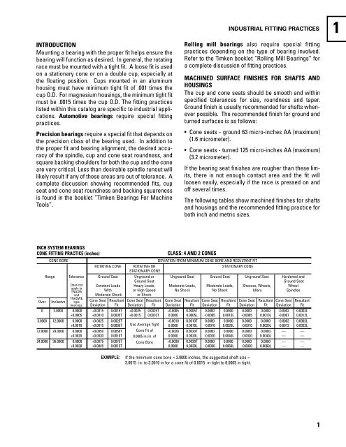
The following tables show machined finishes for shafts<br />
and housings and the recommended fitting practice for<br />
both inch and metric sizes.<br />
INCH SYSTEM BEARINGS<br />
CONE FITTING PRACTICE (inches)<br />
CLASS: 4 AND 2 CONES<br />
CONE BORE<br />
DEVIATION FROM MINIMUM CONE BORE AND RESULTANT FIT<br />
ROTATING CONE ROTATING OR STATIONARY CONE<br />
STATIONARY CONE<br />
Range Tolerance Ground Seat Unground or Unground Seat Ground Seat Unground Seat Hardened and<br />
Ground Seat<br />
Ground Seat<br />
Constant Loads Heavy Loads, Moderate Loads, Moderate Loads, Sheaves, Wheels, Wheel<br />
With or High Speed No Shock No Shock Idlers Spindles<br />
Moderate Shock or Shock<br />
Does not<br />
apply to<br />
TNASW<br />
and<br />
Over Inclusive<br />
TNASWE.<br />
type Cone Seat Resultant Cone Seat Resultant Cone Seat Resultant Cone Seat Resultant Cone Seat Resultant Cone Seat Resultant<br />
bearings. Deviation Fit Deviation Fit Deviation Fit Deviation Fit Deviation Fit Deviation Fit<br />
0 3.0000 0.0000 +0.0015 0.0015T +0.00<strong>25</strong> 0.00<strong>25</strong>T +0.0005 0.0005T 0.0000 0.0000 0.0000 0.0000 -0.0002 0.0002L<br />
+0.0005 +0.0010 0.0005T +0.0015 0.0010T 0.0000 0.0005L -0.0005 0.0010L -0.0005 0.0010L -0.0007 0.0012L<br />
3.0000 12.0000 0.0000 +0.00<strong>25</strong> 0.00<strong>25</strong>T +0.0010 0.0010T 0.0000 0.0000 0.0000 0.0000 -0.0002 0.0002L<br />
+0.0010 +0.0015 0.0005T Use Average Tight 0.0000 0.0010L -0.0010 0.0020L -0.0010 0.0020L -0.0012 0.0022L<br />
12.0000 24.0000 0.0000 +0.0050 0.0050T Cone Fit of +0.0020 0.0020T 0.0000 0.0000 0.0000 0.0000 — —<br />
+0.0020 +0.0030 0.0010T 0.0005 in./in. of 0.0000 0.0020L -0.0020 0.0040L -0.0020 0.0040L — —<br />
24.0000 36.0000 0.0000 +0.0075 0.0075T Cone Bore +0.0030 0.0030T 0.0000 0.0000 0.0000 0.0000 — —<br />
+0.0030 +0.0045 0.0015T 0.0000 0.0030L -0.0030 0.0060L -0.0030 0.0060L — —<br />
EXAMPLE: If the minimum cone bore = 3.0000 inches, the suggested shaft size =<br />
3.0015 in. to 3.0010 in for a cone fit of 0.0015 in tight to 0.0005 in tight.<br />
1