Base Unit Fan Heater Model: BFH24BWSR - Glen Dimplex Ireland
Base Unit Fan Heater Model: BFH24BWSR - Glen Dimplex Ireland
Base Unit Fan Heater Model: BFH24BWSR - Glen Dimplex Ireland

You also want an ePaper? Increase the reach of your titles
YUMPU automatically turns print PDFs into web optimized ePapers that Google loves.
Contact Details<br />
Please note that some of the contact details on<br />
this PDF document may not be current.<br />
Please use the following details if you need to<br />
contact us:<br />
Telephone: 0844 879 3588<br />
Email: customer.services@gdcgroup.co.uk<br />
The customer support section of our website also features a wide<br />
range of information which may be of use to you and is available<br />
24 hours a day. It includes:<br />
• Operating and installation instructions<br />
• Easy ‘How to use’ guides for storage heaters<br />
• Service and repairs<br />
• Where to buy our products<br />
• Literature downloads<br />
• Heating requirement calculator<br />
Visit ‐ www.dimplex.co.uk/support<br />
A division of GDC Group Ltd<br />
Millbrook House Grange Drive Hedge End Southampton SO30 2DF<br />
www.dimplex.co.uk<br />
Registered No: 1313016 England<br />
VAT GB 287 1315 50004<br />
EEE Producer Registration Number –<br />
WEE/GE0057TS<br />
Paper from sustainable sources
Installation & Operating Instructions<br />
<strong>Base</strong> <strong>Unit</strong> <strong>Fan</strong> <strong>Heater</strong><br />
<strong>Model</strong>: <strong>BFH24BWSR</strong> 08/17337/7 Issue 7 Oct ‘08<br />
IMPORTANT: These instructions should be read and carefully retained by the user.<br />
Safety Warnings<br />
• DO NOT COVER OR OBSTRUCT the air inlet or outlet grille.<br />
• ENSURE THE APPLIANCE IS EARTHED.<br />
• Do not place heater immediately below a socket outlet.<br />
• If the appliance is covered, there is a risk of fire.<br />
• Do not use this heater with young children unattended.<br />
• Do not use this heater in areas where excessive dust exists.<br />
• Do not touch or obstruct the grille areas when the heater is in operation.<br />
• If the supply cord is damaged it must be replaced by the manufacturer or service agent or a similarly qualified<br />
person in order to avoid a hazard.<br />
Introduction<br />
This heater has been designed for fitting in the space behind the plinth of floor standing kitchen units or other fitted furniture<br />
units. It is recommended that the heater is not installed under cupboards used for storing perishable goods. It can be<br />
accommodated in plinths with a minimum height of 120mm, and is suitable for cupboards of 500mm width and above.<br />
Installation<br />
The installation of this appliance should be carried out by a competent electrician and be in accordance with the current<br />
IEE wiring regulations.<br />
Before undertaking installation work, ensure the electricity supply is disconnected from any relevant fixed wiring.<br />
The heater is more easily fitted during the installation of new furniture units, or on existing furniture units if they can be<br />
temporarily moved from their position against the wall. If an existing furniture unit cannot be moved, then it may be<br />
necessary to remove the back of the unit in order to gain access to carry out the wiring installation.<br />
Before installing the unit consider the location with respect to the following;<br />
• The electrical supply and cable length.<br />
• Position heater to deliver heat effectively without causing personal discomfort from overheating while standing at<br />
work surfaces etc.<br />
• Minimum plinth height of 120mm and minimum furniture unit width of 500mm.<br />
Procedure<br />
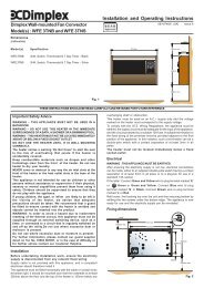
1. Cutting the aperture in the Plinth<br />
Cut aperture in furniture unit plinth to<br />
dimensions shown. This must be<br />
positioned so that the minimum distance<br />
from the bottom of the aperture to the<br />
TOP surface of any floor covering is not<br />
less than 12mm and not more than<br />
25mm.<br />
If an overhang above the heater is greater<br />
than 75mm, then a distance of at least<br />
100mm must be maintained between the<br />
overhang and the uppermost part of the<br />
heater.<br />
Note: If fitted in corner with adjacent<br />
cupboards to left hand side of heater then<br />
a distance of at least 150mm must be<br />
maintained between the left hand end of<br />
the heater and the front of the adjacent<br />
cupboard door.<br />
*This dimension must be maintained<br />
above the top surface of any floor<br />
covering material. All dimensions in<br />
millimetres.
2. Power supply connection<br />
Check that the supply voltage details on the heater are in accordance with your electricity supply. A 2.5 metre length of<br />
inter-connecting cable is supplied. The 6 core inter-connecting cable should be routed from the plinth space to the<br />
connection box, ensuring that the cable is left with enough slack to allow removal of the appliance for maintenance.<br />
The cable must be protected from any sharp edges.<br />
a.) Remote Control Switch Panel<br />
Determine desired position for remote control switch<br />
panel above work bench i.e. 900mm minimum above<br />
floor level. It is designed for use with either a surface<br />
mounted or flush mounted box as listed in the Table<br />
opposite. The left hand column of the Table indicates<br />
the type of conduit/trunking required, if any, and the right<br />
hand column indicates the corresponding two gang box<br />
for the control switch panel. Fix the chosen mounting<br />
box in position.<br />
b.) Electrical Connection to Remote Control Panel<br />
Strip back the outer sheath of the inter-connecting cable<br />
by 125mm, at both ends. The conductor sheath should<br />
be stripped back by 8mm. Select suitable trunking or<br />
conduit from the Table if required. Connect remote<br />
control switch panel to the six core inter-connecting<br />
cable, in accordance with the wiring diagram.<br />
If the 2.5 metre length of cable supplied is insufficient and a substitute cable is used, Ensure that the conductors are of<br />
minimum 1.5mm² cross-sectional area. The same size of conductor should be used to link the switch and fuse<br />
terminals on the remote control switch panel as indicated in the wiring diagram.<br />
c.) Electrical Connection to Appliance<br />
Flush or Surface<br />
Mounting<br />
Conduit/Trunking<br />
1. Embedded – Rounded<br />
or oval conduit<br />
2. Surface Mounting minitrunking<br />
3. Surface Mounting –<br />
Cable clipped to wall<br />
4. DryLining Box<br />
Two Gang box for<br />
Remote Control Switch<br />
MK Switches<br />
1. MK 892 ALM (Metal)<br />
2. Marshall Tufflex MSSB<br />
16 (PVC White)<br />
3. MK 2142 WHI (White<br />
Moulded)<br />
4. Marshall Tufflex MDLB<br />
2 (Plastic)<br />
Remove the screws securing the top, front and rear covers in order to gain access to the terminal block. Feed the 6<br />
core flexible inter-connecting cable through the cable-clamp at the side of the heater and connect it to the terminal block<br />
in accordance with the wiring diagram. It may be necessary to remove the terminal block from its fixing while making<br />
connections to it.<br />
3. Fitting the Rear Support Bracket<br />
The heater is supplied with a rear support bracket. Fit to the back of the appliance with the two screws supplied. Adjust<br />
the rear support bracket so that the vertical distance from the underside of the appliance to bottom of the rear support<br />
bracket equals the vertical distance from the floor in the cupboard space to the bottom of the aperture opening. The<br />
slots in the rear support bracket allow it to be adjusted to the required height.<br />
4. Marking the Fixing Positions<br />
Slide the heater into position in the plinth aperture. Mark the six fixing holes (two on each side and two on the top<br />
Remove the heater and drill 2mm pilot holes.<br />
5. Mounting the <strong>Heater</strong> into the Plinth<br />
When the cable connection has been made and the rear support bracket adjusted, slide the heater into the aperture<br />
ensuring that it is adequately supported and that the inlet grille is not obstructed. Use the six screws provided to secure<br />
the heater to the plinth. (See point 6 below for optional grille fitting).<br />
6. Colour Options.<br />
Your BFH is supplied with a choice of 3 different finishes, Brown (supplied with the heater), White or Stainless Steel.<br />
Your white grille & stainless steel grille are supplied separately (in plastic bags) as an attachment for the front of the<br />
heater. If you prefer the white or the stainless steel finish, place the chosen grille against the heater before fixing the<br />
heater to the plinth. Use the six screws to secure it to the front of the heater / plinth.<br />
Operation<br />
The fan is brought into operation using the switch marked <strong>Fan</strong> on the<br />
remote control switch panel. The heating elements will not function<br />
until the fan is operating. The switches marked ‘I‘ and ‘II’ control the<br />
heating elements. The switch marked ‘I’ controls the 800W element.<br />
The switch marked ‘II’ controls the 1600W element. When both<br />
switches are ON 2400W heat output is available.
Operation of Thermostat<br />
1. The heater incorporates a variable thermostat which is controlled<br />
by a knob situated on the top right hand side of the front panel.<br />
The knob is marked *, 1 - 6, MAX, representing a temperature<br />
range of 5°C to 30°C. Lowest setting provides frost protection<br />
level.<br />
2. Turn thermostat knob to maximum. When the room has reached<br />
the desired comfort level turn back the knob until the thermostat<br />
just ' clicks ' off. If the knob is left in this position the room<br />
temperature will be maintained automatically at the chosen level.<br />
Remember<br />
If, when the heater is switched on, the room temperature is above that selected on the thermostat knob the heater will not<br />
operate. This is as it should be, and the thermostat is performing its function correctly. Should a higher temperature be<br />
required than the one selected, then it will be necessary to turn the thermostat knob to a higher setting to bring the heater<br />
into operation.<br />
Mains Indicator Neon Lens<br />
Located at the bottom left of the front panel, the ‘mains indicator neon lens’ is to indicate when there is electrical supply to<br />
the heater and comes on when the fan switch, on the remote switch assembly is selected.<br />
Cleaning & User Maintenance<br />
WARNING: DISCONNECT SUPPLY before carrying out maintenance.<br />
General Cleaning<br />
External appearance can be maintained by wiping occasionally with a<br />
damp cloth; for stain removal, a weak soap solution can be applied, then<br />
wipe dry.<br />
Internal Cleaning & Maintenance<br />
To help prevent the build up of dust and fluff in the heater it is advisable to<br />
apply the soft brush attachment of a vacuum cleaner to the grille<br />
occasionally (fig. 1).<br />
From time to time it may be necessary to remove the heater from the<br />
furniture unit so that the interior of the heater and the heater compartment<br />
can be cleared of any accumulated dust or fluff by means of a vacuum<br />
cleaner (fig. 2).<br />
To remove, unscrew the six fixing screws and withdraw the appliance from<br />
the plinth.<br />
To gain access to the inside of the appliance remove the screws securing<br />
the top cover.<br />
Clean the interior of the heater using the soft brush attachment of a<br />
vacuum cleaner, taking care not to damage the fan.<br />
Refit the top cover. The interior compartment of the furniture unit should<br />
also be cleared of dust and fluff using the vacuum cleaner nozzle (fig. 3).<br />
Remount the heater in the plinth ensuring the rear support bracket is still<br />
adjusted correctly. The electricity supply to the heater can now be<br />
switched back on.<br />
Safety – overheat protection<br />
For your safety, this appliance is fitted with a thermal cut-out. In the event that the product overheats, the cut-out switches<br />
the heater off automatically. To bring the heater back into operation, remove the cause of overheating, and then turn off the<br />
electrical supply to the heater for a few minutes. When the heater has cooled sufficiently reconnect and switch on the<br />
heater.<br />
If the cut-out operates repeatedly, contact your supplier<br />
Procedure for resetting the cut-out;<br />
A. Disconnect the electricity supply to the appliance either by switching off at the isolating switch panel.<br />
B. Determine what has caused the cut-out to operate and rectify.<br />
(Note: This should only be undertaken by competent persons with experience of repairing electrical appliances and<br />
in full knowledge of the possible hazards involved).<br />
C. After a short time delay to allow the appliance to cool down, all that is required to return the heater to normal<br />
operation is to switch the electricity supply back on.
Replacing 13amp fuse<br />
The 13amp fuse must be ASTA approved to BS1362. The fuse may be replaced by pulling out the fuse holder, marked<br />
‘fuse’, on the remote switch assembly until the fuse is dislodged. The new fuse should then be located and held in position<br />
while the fuse holder is pushed back into position.<br />
Circuit Diagram<br />
Recycling<br />
For electrical products sold within the European Community.<br />
At the end of the electrical products useful life it should not be disposed of with household waste. Please recycle<br />
where facilities exist. Check with your Local Authority or retailer for recycling advice in your country.<br />
After Sales Service<br />
Your product is guaranteed for two years from the date of purchase.<br />
Within this period, we undertake to repair or exchange this product free of charge (subject to availability) provided it has<br />
been installed and operated in accordance with these instructions.<br />
Your rights under this guarantee are additional to your statutory rights, which in turn are not affected by this guarantee.<br />
Should you require after sales service or assistance with this product please go to www.dimplex.co.uk where you will find<br />
our self help guide by clicking on “After Sales” or ring our help desk on 0845 600 5111 (UK) or 01 842 4833 ROI.<br />
Spare parts are also available on the website www.dimplex.co.uk.<br />
Please retain your receipt as proof of purchase.<br />
This product complies with the European Safety Standard EN60335-2-30 and the European Standard for<br />
Electromagnetic Compatibility (EMC) EN55014, EN60555-2 and EN60555-3. These cover the essential<br />
requirements of EEC Directives 2006/95/EC and 2004/108/EC.<br />
<strong>Dimplex</strong> UK Limited<br />
Millbrook House<br />
Grange Drive<br />
Hedge End<br />
Southampton<br />
www.dimplex.co.uk<br />
Hampshire SO30 2DF Republic of <strong>Ireland</strong> 01 8424833<br />
[c] <strong>Dimplex</strong> UK Limited<br />
All rights reserved. Material contained in this publication may not be reproduced in whole or in part, without prior permission in writing of <strong>Dimplex</strong> UK Limited.