Installation & Service Manual - Hill Phoenix
Installation & Service Manual - Hill Phoenix
Installation & Service Manual - Hill Phoenix

You also want an ePaper? Increase the reach of your titles
YUMPU automatically turns print PDFs into web optimized ePapers that Google loves.
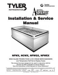
<strong>Installation</strong> & <strong>Service</strong><br />
<strong>Manual</strong><br />
LD48, LD54, LD60, LD72<br />
MULTI-DECK SELF-SERVICE DELI MERCHANDISERS<br />
Medium Temperature Refrigerated Display Cases<br />
This manual has been designed to be used in conjunction with the<br />
General (UL/NSF) <strong>Installation</strong> & <strong>Service</strong> <strong>Manual</strong>.<br />
Save the Instructions in Both <strong>Manual</strong>s for Future Reference!!<br />
This merchandiser conforms to the American National Standard Institute & NSF International Health and Sanitation standard ANSI/NSF 7 - 2003.<br />
PRINTED IN Specifications subject to REPLACES ISSUE PART<br />
IN U.S.A. change without notice. EDITION 10/05 DATE 4/07 NO. 9807020 REV. A<br />
Tyler Refrigeration * Niles, Michigan 49120
LD48, LD54, LD60, LD72<br />
CONTENTS<br />
Page<br />
Specifications<br />
LD48/LD54/LD60/LD72 Specification Sheets . . . . . . . . . . . . . . . . . . 4<br />
Pre-<strong>Installation</strong> Responsibilities . . . . . (See General-UL/NSF I&S <strong>Manual</strong>)<br />
<strong>Installation</strong> Procedures<br />
Carpentry Procedures . . . . . . . . . . . . . . . . . . . . . . . . . . . . . . . . . . . 6<br />
Case Pull-Up Locations . . . . . . . . . . . . . . . . . . . . . . . . . . . . . . . . . . 6<br />
Electrical Procedures . . . . . . . . . . . . . . . . . . . . . . . . . . . . . . . . . . . . 6<br />
Electrical Considerations . . . . . . . . . . . . . . . . . . . . . . . . . . . . . . . . . . 6<br />
Plumbing Procedures . . . . . . . . (See General-UL/NSF I&S <strong>Manual</strong>)<br />
Refrigeration Procedures . . . . . (See General-UL/NSF I&S <strong>Manual</strong>)<br />
Defrost Information . . . . . . . . . . . . . . . . . . . . . . . . . . . . . . . . . . . . . 6<br />
Defrost Control Chart . . . . . . . . . . . . . . . . . . . . . . . . . . . . . . . . . . . . 6<br />
<strong>Installation</strong> Procedure Check Lists (See Gen.-UL/NSF I&S <strong>Manual</strong>)<br />
Wiring Diagrams . . . . . . . . . . . . . . . . . . . . . . . . . . . . . . . . . . . . . . . . . . . . 6<br />
LD48/LD54/LD60/LD72 Domestic & Export (50Hz) 4’ Case Circuits 7<br />
LD48/LD54/LD60/LD72 Dom. & Exp. (50Hz) 6’ & 8’ Case Circuits . 8<br />
LD48/LD54/LD60/LD72 Domestic & Export (50Hz) 12’ Case Circuits 9<br />
Cleaning and Sanitation . . . . . . . . . . . . (See General-UL/NSF I&S <strong>Manual</strong>)<br />
Component Removal and <strong>Installation</strong> Instructions for Cleaning 10<br />
Shelves and Shelf Brackets . . . . . . . . . . . . . . . . . . . . . . . . . . . . . . . 10<br />
Bottom Trays . . . . . . . . . . . . . . . . . . . . . . . . . . . . . . . . . . . . . . . . . . 10<br />
Front Air Ducts . . . . . . . . . . . . . . . . . . . . . . . . . . . . . . . . . . . . . . . . 10<br />
Rear Duct Panels . . . . . . . . . . . . . . . . . . . . . . . . . . . . . . . . . . . . . . 10<br />
Discharge Air Honeycomb . . . . . . . . . . . . . . . . . . . . . . . . . . . . . . . . 10<br />
Top Duct . . . . . . . . . . . . . . . . . . . . . . . . . . . . . . . . . . . . . . . . . . . . 10<br />
Front Cladding . . . . . . . . . . . . . . . . . . . . . . . . . . . . . . . . . . . . . . . . 11<br />
Page 2 April, 2007
<strong>Installation</strong> & <strong>Service</strong> <strong>Manual</strong><br />
LD48, LD54, LD60, LD72<br />
Page<br />
General Information<br />
NSF Product Thermometer . . . . . . . . . . . . . . . . . . . . . . . . . . . . . . 11<br />
<strong>Service</strong> Instructions<br />
Preventive Maintenance . . . . . . (See General-UL/NSF I&S <strong>Manual</strong>)<br />
Light Servicing<br />
Ballast and Lighting Locations . . . . . . . . . . . . . . . . . . . . . . . . . . . . . 11<br />
Fan Blade and Motor Replacement (See Gen.-UL/NSF I&S <strong>Manual</strong>)<br />
Color Band and Bumper Replacement (See Gen.-UL/NSF I&S Man.)<br />
Parts Information<br />
Cladding and Optional Trim Parts List . . . . . . . . . . . . . . . . . . . . . 12<br />
Operational Parts List . . . . . . . . . . . . . . . . . . . . . . . . . . . . . . . . . . 14<br />
TYLER Warranty . . . . . . . . . . . . . . . . . (See General-UL/NSF I&S <strong>Manual</strong>)<br />
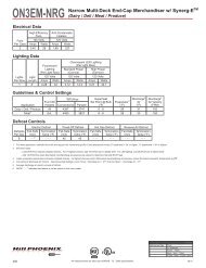
The following Multi-Deck, Self-<strong>Service</strong>, Medium Temperature Deli Merchandiser models<br />
are covered in this manual:<br />
MODELS<br />
LD48<br />
LD54<br />
LD60<br />
LD72<br />
DESCRIPTION<br />
4’, 6’, 8’ & 12’ MULTI-DECK SELF-SERVICE DELI MERCHANDISERS<br />
4’, 6’, 8’ & 12’ MULTI-DECK SELF-SERVICE DELI MERCHANDISERS<br />
4’, 6’, 8’ & 12’ MULTI-DECK SELF-SERVICE DELI MERCHANDISERS<br />
4’, 6’, 8’ & 12’ MULTI-DECK SELF-SERVICE DELI MERCHANDISERS<br />
October, 2005 Page 3
LD48, LD54, LD60, LD72<br />
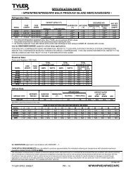
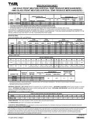
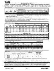
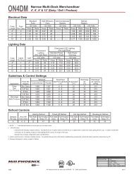
SPECIFICATIONS<br />
LD48/LD54/LD60/LD72 Multi-Deck Self-<strong>Service</strong> Deli Merchandisers<br />
Page 4 April, 2007
<strong>Installation</strong> & <strong>Service</strong> <strong>Manual</strong><br />
LD48, LD54, LD60, LD72<br />
April, 2007 Page 5
LD48, LD54, LD60, LD72<br />
INSTALLATION PROCEDURES<br />
Carpentry Procedures<br />
Case Pull-Up Locations<br />
The LD models have three pull-ups at each<br />
end of the case. Pull-ups A, B and C are<br />
located as shown and should be installed and<br />
tightened starting with A and finishing with C.<br />
See “General-UL/NSF I&S <strong>Manual</strong>” for<br />
line-up assembly instructions.<br />
Electrical Procedures<br />
Electrical Considerations<br />
CAUTION<br />
Make sure all electrical connections at<br />
components and terminal blocks are tight.<br />
NOTE<br />
Since the ront cladding is shipped loose,<br />
the wiring has immediate access.<br />
Case Fan Circuit<br />
This circuit is to be supplied by an uninterrupted,<br />
protected 120V circuit. The case fan<br />
circuit is not cycled during defrost on any of<br />
these models.<br />
Fluorescent Lamp Circuit<br />
LD case lighting is supplied by T-8 electronic<br />
ballast lights. It is controlled by a light switch<br />
in each case. The standard lighting is 1-row<br />
of T-8 canopy lights. Optional T-8 shelf lights<br />
are also available on the LD cases. Up to 3<br />
rows on the LD48 and LD54; up to 4 rows on<br />
the LD60; and up to 5 rows on the LD72<br />
models.<br />
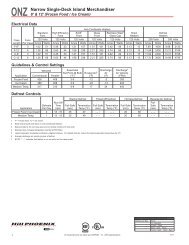
Defrost Information<br />
See “General-UL/NSF I&S <strong>Manual</strong>” for<br />
operational descriptions for Off Time<br />
defrost control.<br />
Defrost Control Chart<br />
Defrost<br />
Defrost Defrosts Duration Term.<br />
Type Per Day (Min) Temp.<br />
LD(48/54/60/72)<br />
Off Time 6 20 -----<br />
WIRING DIAGRAMS<br />
ELECTRICIAN NOTE - OVERCURRENT<br />
PROTECTION<br />
120V circuits should be protected by 15 or 20 Amp<br />
devices per the requirements noted on the cabinet<br />
nameplate or the National Electrical Code, Canadian<br />
Electrical Code - Part 1, Section 28. 208V defrost<br />
circuits employ No. 12 AWG field wire leads for field<br />
connections. On remote cases intended for end to<br />
end line-ups, bonding for ground may rely upon the<br />
pull-up bolts.<br />
The following wiring diagrams on pages 7<br />
thru 9 will cover the LD48, LD54, LD60 and<br />
LD72 case and lighting circuits.<br />
Page 6 April, 2007
LD48/54/60/72 Domestic & Export (50Hz) Case Circuits (4’ Cases)<br />
October, 2005 Page 7
LD48/54/60/72 Domestic & Export (50Hz) Case Circuits (6’ & 8’ Cases)<br />
Page 8 April, 2007
LD48/54/60/72 Domestic & Export (50Hz) Case Circuits (12’ Cases)<br />
October, 2005 Page 9
LD48, LD54, LD60, LD72<br />
CLEANING AND SANITATION<br />
Component Removal and <strong>Installation</strong><br />
Instructions for Cleaning<br />
Shelves and Shelf Brackets<br />
1. Remove product from shelves.<br />
2. If shelf has a light, unplug the light cord<br />
from the socket in the rear duct panel.<br />
Completely insert socket cover in the light<br />
socket to protect the receptacle.<br />
3. Push shelves back and then lift up and out<br />
to remove them from the shelf brackets.<br />
4. Remove shelf brackets from slots in rear<br />
uprights.<br />
5. After cleaning, replace in reverse order.<br />
Bottom Trays<br />
1. Remove product from bottom of case.<br />
2. Grasp and lift out each of the bottom trays<br />
from the case interior.<br />
3. After cleaning, replace in reverse order.<br />
Front Air Ducts<br />
1. Remove lower trays, see this page.<br />
2. Lift out front air duct sections.<br />
3. After cleaning, replace in reverse order.<br />
Rear Duct Panels<br />
(w/o Shelf Light Sockets)<br />
1. Remove shelves and bottom trays, see<br />
above.<br />
2. Remove mounting screws and rear duct<br />
panels from case.<br />
3. After cleaning, replace and secure rear<br />
duct panels in reverse order.<br />
(with Shelf Light Sockets)<br />
1. Remove mirrors, shelves and bottom<br />
trays, see this page.<br />
2. Remove mounting screws from rear duct<br />
panel.<br />
3. Slowly lift out rear duct panel until the<br />
shelf harness connector near the top of<br />
the panel can be accessed.<br />
4. Disconnect shelf harness connector and<br />
complete removing the rear duct panel.<br />
WARNING<br />
Rear duct panels with electrical receptacles<br />
can be cleaned without removing the<br />
electrical receptacles. Do not get moisture<br />
on electrical wires when cleaning under<br />
this cover. Moisture on wires could cause<br />
premature product failure and/or personal<br />
injury or death from electrical shock.<br />
5. After cleaning, reconnect the shelf harness<br />
connector: install the top socket<br />
assembly: replace and secure rear duct<br />
panels in reverse order.<br />
Discharge Air Honeycomb<br />
1. Loosen screws securing rear retainer<br />
plate.<br />
NOTE<br />
Note position of the honeycomb grid during<br />
removal so it can be reinstalled the<br />
same way.<br />
2. Slide rear retainer plate back until the<br />
honeycomb grid sections can be removed<br />
from the top duct.<br />
CAUTION<br />
Improper installation of the honeycomb<br />
grid section could result in improper air<br />
flow and/or poor refrigeration.<br />
3. After cleaning, replace honeycomb grid<br />
sections as they were removed and<br />
secure with the rear retainer plate and<br />
screws.<br />
Top Duct<br />
1. Remove shelves and shelf brackets, see<br />
above.<br />
2. Remove screws, rear retainer plate and<br />
honeycomb grid sections from top of<br />
case.<br />
3. Remove screws and top duct from case.<br />
4. After cleaning, replace top duct and<br />
remaining components in reverse order.<br />
Page 10 April, 2007
<strong>Installation</strong> & <strong>Service</strong> <strong>Manual</strong><br />
Front Cladding<br />
1. Remove front kickplate form kickplate<br />
supports. (See General-UL/NSF I&S<br />
<strong>Manual</strong>.)<br />
2. Remove mounting screws from top and<br />
bottom of front cladding and remove front<br />
cladding.<br />
3. After cleaning, replace in reverse order.<br />
GENERAL INFORMATION<br />
NSF Product Thermometer<br />
<strong>Installation</strong><br />
LD48, LD54, LD60, LD72<br />
Light Servicing<br />
Ballast and Lighting Locations<br />
1. Unwrap the thermometer and bracket<br />
assembly shipped loose with the case.<br />
2. Position bracket in front right corner of the<br />
right-most bottom tray. Making sure the<br />
bracket is 5/8” in from the right edge, use<br />
the bracket holes as a template for where<br />
to drill the holes.<br />
3. Drill two .196” holes in the bottom tray.<br />
NOTE<br />
For ease of installation, position the washers<br />
and capnuts on the top side of the<br />
bracket and bottom tray.<br />
All light ballasts for the canopy lights and<br />
optional shelf lights are located inside each<br />
of the light channel assemblies. To access<br />
the light ballasts, remove the screws and the<br />
light channel cover from the light channel<br />
assembly. The canopy lights are under the<br />
canopy light channel in the top of the case.<br />
The optional shelf lights are mounted in<br />
separate light channels under the front of<br />
each shelf section.<br />
NOTE<br />
See “General-UL/NSF I&S <strong>Manual</strong>” for<br />
T-8 ballast and lamp, fan blade & motor<br />
and color band & bumper replacement<br />
instructions.<br />
4. Mount the bracket to the bottom tray with<br />
two screws, washers and capnuts.<br />
October, 2005 Page 11
LD48, LD54, LD60, LD72<br />
PARTS INFORMATION<br />
Cladding and Optional Trim Parts List<br />
LD48/LD54/LD60/LD72<br />
Item Description 4’ 6’ 8’ 12’<br />
1 Front Top Cladding, Ptd. 9802550 9802580 9801330 9802582<br />
Screw 9024814 (3) 9024814 (3) 9024814 (3) 9024814 (4)<br />
2 Close-off, RH Top Shelf 9802328 9802328 9802328 9802328<br />
Close-off, LH Top Shelf 9802329 9802329 9802329 9802329<br />
Screw 9024814 (2) 9024814 (2) 9024814 (2) 9024814 (2)<br />
3 Top Joint Trim, Ptd. 9802312 9802312 9802312 9802312<br />
Screw 9024814 (4) 9024814 (4) 9024814 (4) 9024814 (4)<br />
4 Plexiglas, Curved 9802560 9800193 9800194 9800193 (2)<br />
RH Plexiglas Trim Assembly 9800225 9800225 9800225 9800225 (2)<br />
LH Plexiglas Trim Assembly 9800226 9800226 9800226 9800226 (2)<br />
Plexiglas Retainer 9802561 9800203 9053834 9800203 (2)<br />
5 Plexiglas Joint Trim 9800211 9800211 9800211 9800211<br />
Screw 5100217 (2) 5100217 (2) 5100217 (2) 5100217 (2)<br />
6 Lower Front Cladding, Ptd. 9806245 9801369 9801370 9801371<br />
Screw 5183536 (6) 5183536 (8) 5183536 (10) 5183536 (12)<br />
7 Lwr. Frt. Cladding Joint Trim, Ptd. 9801250 9801250 9801250 9801250<br />
Screw 5205439 (2) 5205439 (2) 5205439 (2) 5205439 (2)<br />
8 Color Band, Ptd. 9023791 9023796 9023799 9023801<br />
9 Color Band Backer, Ptd. 9040223 9040223 9040223 9040223<br />
10 Bumper ----------------- color by order -----------------<br />
11 Bumper Backer ----------------- color by order -----------------<br />
12 Bumper End Trim ----------------- color by order -----------------<br />
13 Bumper Retainer ----------------- color by order -----------------<br />
Shoulder Screw 9025833 (8) 9025833 (12) 9025833 (16) 9025833 (24)<br />
14 Bumper Retainer Backer, Ptd. 9025316 9025316 9025316 9025316<br />
15 Metal Kickplate, Ptd. 9039267 9039268 9039269 9039270<br />
Page 12 April, 2007
<strong>Installation</strong> & <strong>Service</strong> <strong>Manual</strong><br />
LD48, LD54, LD60, LD72<br />
Item Description 4’ 6’ 8’ 12’<br />
16 Kickplate Joint Trim, Ptd. 9039020 9039020 9039020 9039020<br />
Screw, Blk. 9037551 (4) 9037551 (5) 9037551 (6) 9037551 (6)<br />
17 Kickplate Support 9043461 (2) 9043461 (3) 9043461 (4) 9043461 (4)<br />
Screw 5183536 (4) 5183536 (6) 5183536 (8) 5183536 (8)<br />
18 Base End Close-off, Ptd. 9801693 (2) 9801693 (2) 9801693 (2) 9801693 (2)<br />
Screw (per end close-off) 5048626 (2) 5048626 (2) 5048626 (2) 5048626 (2)<br />
19 Horizontal End Trim 5964733 5964733 5964733 5964733<br />
October, 2005 Page 13
LD48, LD54, LD60, LD72<br />
Operational Parts List<br />
Case Usage<br />
Domestic<br />
Electrical Circuit<br />
115 Volt 60 Hertz<br />
Case Size 4’ 6’ 8’ 12’<br />
Fan Motors 5243498 5243498 5243498 5243498<br />
(LD48/LD54/LD60/LD72) 9 Watt 9 Watt 9 Watt 9 Watt<br />
Fan Motor Brackets 5205112 5205112 5205112 5205112<br />
Fan Bracket Plate 9041077 9041077 9041077 9041077<br />
Fan Blades (8.75” 30° 5B) 9407319 9407319 9407319 9407319<br />
Opt. ECM Fan Motors 9025000 9025000 9025000 9025000<br />
(LD48/LD54/LD60/LD72) 12 Watt 12 Watt 12 Watt 12 Watt<br />
Opt. ECM Motor Brackets 5205112 5205112 5205112 5205112<br />
Opt. ECM Fan Blades 9407319 9407319 9407319 9407319<br />
(8.75” 30° 5B)<br />
T-8 Lamp Ballast (canopy & shelf)<br />
(can. 1-row) 5991029 5991029 5991029 9322286<br />
(shelf) 5966635 5966635 5966635 9322288<br />
T-8 Lampholder (canopy) 9041897 9041897 9041897 9041897<br />
(shelf) 9041897 9041897 9041897 9041897<br />
NSF Product Thermometer 5967100 5967100 5967100 5967100<br />
For information on operational parts not listed above contact the TYLER <strong>Service</strong> Parts<br />
Department.<br />
Page 14 April, 2007