

Frame Layout and Parts List 10
Frame Layout and Parts List 10
Frame Layout and Parts List 10

Create successful ePaper yourself
Turn your PDF publications into a flip-book with our unique Google optimized e-Paper software.
SALES OFFICES:<br />
1<strong>10</strong>0 BURCH DRIVE<br />
PO BOX 3477<br />
EVANSVILLE, IN 47733 USA<br />
EC4164<br />
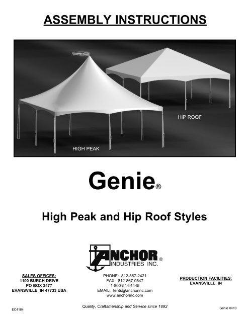
ASSEMBLY INSTRUCTIONS<br />
HIGH PEAK<br />
Genie®<br />
PHONE: 812-867-2421<br />
FAX: 812-867-0547<br />
1-800-544-4445<br />
EMAIL: tents@anchorinc.com<br />
www.anchorinc.com<br />
Quality, Craftsmanship <strong>and</strong> Service since 1892<br />
HIP ROOF<br />
High Peak <strong>and</strong> Hip Roof Styles<br />
PRODUCTION FACILITIES:<br />
EVANSVILLE, IN<br />
Genie 04<strong>10</strong>
2<br />
Corner Weldment<br />
Intermediate Weldment<br />
20’ x 40’ Intermediate<br />
Peak Weldment<br />
<strong>10</strong>’ x <strong>10</strong>’ / 15’ x 15’<br />
Peak Weldment<br />
20’ x 20’ Peak<br />
Weldment<br />
20’ x 30’ / 40’ Peak<br />
Weldment<br />
Adjustable<br />
Upright Assembly<br />
High Peak Tube<br />
Assembly<br />
Bag with Top<br />
Manpower Required<br />
Two experienced installers should be able to assemble sizes <strong>10</strong>’ x <strong>10</strong>’, 15’ x 15’, <strong>and</strong> 20’ x 20’. (approximately 30 minutes)<br />
Three experienced installers should be able to assemble the 20’ x 30’. (approximately 30 minutes)<br />
Three experienced installers should be able to assemble the 20’ x 40’. (approximately 45 minutes)<br />
Tools Required<br />
Sledge hammer for stakes (not supplied).<br />
Tape Measure<br />
Component Illustrations<br />
Hip stubs are the<br />
longest tubes.<br />
Hip stubs are the<br />
longest tubes.<br />
Ridge stub tube is<br />
parallel to ground.<br />
Caution:<br />
Please read through this assembly manual completely before beginning your installation. Be sure the proper equipment<br />
<strong>and</strong> safety precautions are in place. We hope that you enjoy the design features of the Genie Tent each time the unit is<br />
installed.<br />
1. Be aware to avoid contact of frame sections with any overhead power lines near the site.<br />
2. Consult the local utility company prior to installation in order to avoid all underground power lines <strong>and</strong> gas lines or other<br />
utility easements.<br />
3. Keep site clear of debris to avoid tripping, especially while carrying frame parts or bundle of fabric.<br />
4. When moving frame sections by h<strong>and</strong>, use proper lifting techniques to protect the back, <strong>and</strong> avoid pinching fingers while<br />
making hardware connections.<br />
5. Do not drag bundle of fabric on concrete, asphalt, or ground as this can cause damage to the fabric from abrasion<br />
through the bag.<br />
6. The installation method described here requires coordination of tasks between workers. A safe installation is dependent<br />
on that coordination. Work cooperatively as a team.<br />
7. This tent is manufactured for use as a temporary sun shade structure. Evacuation is recommended if threatening<br />
or windy weather occurs.
<strong>10</strong>’ x <strong>10</strong>’ & 15’ x 15’ <strong>Frame</strong> <strong>Layout</strong> <strong>and</strong> <strong>Parts</strong> <strong>List</strong><br />
<strong>10</strong>’ x <strong>10</strong>’ <strong>Frame</strong> <strong>Parts</strong> <strong>List</strong><br />
Part No. Qty Description<br />
1 1 <strong>10</strong>’ x<strong>10</strong>’/ 15’ x15’ Peak Weldment<br />
2 4 Adjustable Upright Assembly<br />
3 4 Hip - Nominal length 6’-<strong>10</strong>”<br />
4 4 Eave Tube - Nominal length 9’-3”<br />
5 1 High Peak Tube Assembly<br />
6 4 Corner Weldment<br />
15’ x 15’ <strong>Frame</strong> <strong>Parts</strong> <strong>List</strong><br />
Part No. Qty Description<br />
5<br />
1 1 <strong>10</strong>’ x<strong>10</strong>’/ 15’ x15’ Peak Weldment<br />
2 4 Adjustable Upright Assembly<br />
3<br />
4<br />
4<br />
4<br />
Hip - Nominal length <strong>10</strong>’-8”<br />
Eave Tube - Nominal length 14’-4”<br />
2<br />
6<br />
4<br />
5 1 High Peak Tube Assembly<br />
6 4 Corner Weldment <strong>Frame</strong> <strong>Layout</strong><br />
20’ x 20’ <strong>Frame</strong> <strong>Layout</strong> <strong>and</strong> <strong>Parts</strong> <strong>List</strong><br />
20’ x 20’ <strong>Frame</strong> <strong>Parts</strong> <strong>List</strong><br />
Part No. Qty Description<br />
1 1 20’ x 20’ Peak Weldment<br />
2 8 Adjustable Upright Assembly<br />
3 4 Hip - Nominal length 14’-4”<br />
4 8 Eave Tube - Nominal length 9’-3”<br />
5 1 High Peak Tube Assembly<br />
6 4 Corner Weldment<br />
7 4 Intermediate Weldment<br />
8 4 Rafter Tube - Nominal length <strong>10</strong>’-8”<br />
2<br />
6<br />
7<br />
5<br />
8<br />
<strong>Frame</strong> <strong>Layout</strong><br />
1<br />
1<br />
4<br />
3<br />
3<br />
3
4<br />
3<br />
6<br />
1<br />
7<br />
20’ x 30’ <strong>Frame</strong> <strong>Layout</strong><br />
Part No. 20’ x 30’ Qty.<br />
20’ x 30’ <strong>and</strong> 20’ x 40’ <strong>Frame</strong> <strong>Parts</strong> <strong>List</strong><br />
20’ x 40’ Qty. Description<br />
1 2 2 20’ x 30’/40’ Peak Weldment<br />
2 Not Used 1 Intermediate Peak Weldment<br />
3 <strong>10</strong> 12 Adjustable Upright Assembly<br />
4 11 14 Eave/Ridge Tube - Nominal length 9’-3”<br />
5 6 8 Rafter Tube - Nominal length <strong>10</strong>’-8”<br />
6 4 4 Hip Tube - Nominal length 14’-4”<br />
7 2 2 High Peak Tube Assembly<br />
8 4 4 Corner Weldment<br />
9 6 8 Intermediate Weldment<br />
3<br />
6<br />
1<br />
7<br />
2<br />
20’ x 40’ <strong>Frame</strong> <strong>Layout</strong><br />
4<br />
4<br />
5<br />
4<br />
4<br />
5<br />
8<br />
9<br />
8<br />
9
Step 1<br />
<strong>Layout</strong> corner weldments, intermediate weldments<br />
(when required) <strong>and</strong> eave tubes as shown on corresponding<br />
size frame layout on pages 2 <strong>and</strong> 3.<br />
Start with one of the corner weldments. Insert eave<br />
tubes into the corner weldment being sure that the snap<br />
buttons are securely seated into the corresponding<br />
holes of the weldments. (Figure 1)<br />
Be careful when seating snap buttons to avoid injury.<br />
Proceed all the way around the frame until the entire<br />
perimeter of the frame is assembled.<br />
Step 2<br />
<strong>Layout</strong> the hip tubes <strong>and</strong> the peak weldment in the<br />
proper positions. Insert one end of hip tube into the<br />
corner weldment. Then insert the top end of the hip<br />
tube into the peak weldment. Be sure that all snaps<br />
are seated securely in the weldment holes. Continue<br />
around the tent until all hips are in place. (Figure 2)<br />
On the 20’ x 30’ <strong>and</strong> 20’ x 40’ size frames, you will connect<br />
the ridge tubes (identical to eave tubes) to the peak<br />
weldments (Part 1 ) after connection of the hips. The<br />
20’ x 40’ Intermediate peak weldment (Part 2 ) will be<br />
required to connect the two ridge tubes on the 20’ x 40’<br />
frame. See 20’ x 40’ <strong>Frame</strong> <strong>Layout</strong> on page 3.<br />
Step 3<br />
Next, attach rafter tubes to peak weldment(s) first <strong>and</strong><br />
then to intermediate weldments. Snap in place.<br />
Continue until all rafters are attached. (Figure 3)<br />
Step 4<br />
Spread drop cloths.<br />
Loosely stack the fabric next to one end of the<br />
frame, top side up.<br />
Using two persons, grab two corners of the fabric<br />
<strong>and</strong> drag the fabric up <strong>and</strong> over the frame until the<br />
corners of the fabric are lying on top of their corresponding<br />
corner weldments. A third person may<br />
be required for the 20’ x 30’ or 20’ x 40’ frames.<br />
(Figure 4)<br />
Caution: Be certain at all times that fabric is not<br />
caught on any part of the frame to prevent damage<br />
to the fabric.<br />
20’ x 20’ <strong>Frame</strong> Shown<br />
Figure 2<br />
20’ x 20’ <strong>Frame</strong> Shown Figure 3<br />
Fabric top<br />
Intermediate<br />
weldment<br />
20’ x 20’ <strong>Frame</strong> Shown<br />
20’ x 20’ <strong>Frame</strong> Shown<br />
Corner<br />
weldment<br />
Figure 1<br />
Figure 4<br />
5
Step 5 - High Peak Style Only<br />
If your Genie is the high peak style, you will now need<br />
to retrieve the high peak tube assembly.<br />
Remove the safety pin lock at the bottom of the tube<br />
<strong>and</strong> the hair pin cotter from the top pin (Figure 5).<br />
Set these aside.<br />
Step 6 - High Peak Style Only<br />
Push the top pin of the high peak<br />
tube assembly through the<br />
grommet at the peak of<br />
the tent fabric. (Figure<br />
6a) Raise the high peak<br />
tube assembly up until the<br />
bottom is above the peak<br />
weldment. Slide the high<br />
peak tube assembly down<br />
through the top of the peak<br />
weldment. Let it rest there<br />
on the peak weldment.<br />
Now you may place the<br />
streamer on the top pin <strong>and</strong><br />
insert the hair pin cotter to<br />
keep the streamer <strong>and</strong> fabric<br />
top in place. (Figure 6b)<br />
Now retrieve the safety pin<br />
lock, push the high peak<br />
tube assembly up into position<br />
by aligning the holes of<br />
the peak weldment with the<br />
hole in the high peak tube.<br />
Push the pin lock through<br />
the holes <strong>and</strong> lock into<br />
place. (Figure 6c)<br />
Step 7<br />
Select an adjustable upright, be sure it is in<br />
the lowest position. Insert it into a corner<br />
weldment <strong>and</strong> make sure the snap is seated<br />
into the hole of the weldment.<br />
6<br />
Fabric broken away<br />
for clarity<br />
Peak Weldment<br />
Hair pin cotter<br />
High Peak Tube<br />
Assembly<br />
Figure 6a<br />
Safety pin lock<br />
High Peak Tube Assembly<br />
Top pin with<br />
hair pin cotter<br />
inserted.<br />
Streamer<br />
Peak Grommet<br />
Tent Fabric<br />
Safety Pin<br />
Lock<br />
Peak<br />
Weldment<br />
Figure 5<br />
Figure 6b<br />
Figure 6c<br />
Caution: The Safety Pin Lock with safety latch engaged as shown above (Figure 6c) must be<br />
used at the bottom of the high peak tube assembly.<br />
Safety<br />
Latch<br />
Figure 7
Step 7 (continued)<br />
Continue around the tent inserting <strong>and</strong> securing all of the corner uprights. (On the 20’ x 40’ tent, the center<br />
upright on the 40’ side must also be inserted before proceeding on to the next corner upright). When raising<br />
the tent, be sure to use an appropriate number of persons according the the size of the tent. (Figure 7)<br />
After the corner uprights are attached, insert the rest of the uprights into the intermediate weldments.<br />
Step 8<br />
Now proceed around the tent pulling each corner of the top<br />
down over each corner weldment, making sure tent top is<br />
square onto frame.<br />
If you are using the optional Genie guy kit, you may now install<br />
the eyebolt on the corner weldments. The 20’ x 40’ can also be<br />
guyed at the mid intermediate weldment on the 40’ side. Insert<br />
eyebolt with a washer on outside of weldment <strong>and</strong> one on inside<br />
of weldment. Place nut on top of inside washer <strong>and</strong> tighten.<br />
(See Figure 9b)<br />
Step 9<br />
It is now time to position each upright base plate to the appropriate<br />
spacing <strong>and</strong> secure with a 1” x 30” double-headed stake.<br />
Raise each adjustable upright to the desired height <strong>and</strong> snap<br />
into place. When all of the uprights are raised, feed webs<br />
through D-rings at corners as shown in Figure 9a. Attach the<br />
snap of the tension straps to the d-rings on the fabric at each<br />
upright. Insert the hook of the tension strap into the hole on the<br />
upturned portion of the base plate. Starting with the corners,<br />
tighten the tension strap using the ratchet. (Figure 9a)<br />
Do not over-tension as this may create unsightly wrinkles or<br />
puckering in your tent fabric.<br />
If your unit is the 15’ x 15’ Genie you will now need to fasten<br />
the side release buckles located at the mid eave points<br />
between each corner upright. These are attached to the fabric.<br />
Wrap the bottom buckle around the eave tube <strong>and</strong> fasten to the<br />
top buckle. Pull the loose strap of the upper buckle as needed<br />
so that the top fits snugly onto the frame.<br />
If you are using the optional guy kit, snap the guy webs onto<br />
the eyebolts. (Figure 9b) Place 1” x 30” stakes through oval<br />
ring on guy web <strong>and</strong> drive into the ground at a position of<br />
one foot less than eave height of tent. (i.e. 7’ for 8’ uprights).<br />
Corner stakes are at 45 degrees. Tension the guy webs using<br />
the ratchet.<br />
Note: Stakes <strong>and</strong>/or Web Guy Kits are not included with<br />
<strong>Frame</strong> - must be purchased separately.<br />
Your Genie Tent is now ready to use!<br />
CAUTION:<br />
This product has been designed as a “Light Weight”<br />
Sun Shade <strong>Frame</strong> Tent - Do Not Install or Use During<br />
Windy Weather Conditions.<br />
Adjustable upright<br />
raised to appropriate<br />
height.<br />
Tension strap<br />
snapped to d-rings.<br />
1” x 30”<br />
Double-headed<br />
Stake<br />
Base Plate<br />
Ratchet<br />
Figure 9a<br />
Eyebolt for guy.<br />
Hook of tension<br />
strap through hole<br />
in base plate.<br />
Figure 9b<br />
7
EVANSVILLE, INDIANA<br />
PHONE NUMBER<br />
812· 867· 2421<br />
FAX NUMBER<br />
812· 867· 0547<br />
Anchor products are of superior design <strong>and</strong> operate best within the parameters of these instructions. It is imperative<br />
that the instructions be carefully read <strong>and</strong> COMPLETELY FOLLOWED. Please read installation instructions before the<br />
installation or removal of this product. Installation instructions are available online at www.anchorinc.com or by calling<br />
1-800-544-4445.<br />
CAUTION:<br />
1. For each installation, the installer is solely responsible for evaluating the site <strong>and</strong> the proper securing method<br />
determined. Some soils require different staking or securing than that provided with the tent. Due to this variety of<br />
soil conditions, these are the manufacturer’s suggested sequence of installation procedures. Anchor’s responsibility<br />
is limited to the manufacture of the tent parts <strong>and</strong> materials. We are not responsible for methods that installers may<br />
choose to erect <strong>and</strong> secure the tent to the ground.<br />
2. The number of stakes suggested in the installation instructions do not necessarily meet all or any relevant codes<br />
on the site of the tent installation. The number of stakes suggested will, in many cases, keep the tent erected,<br />
however, due to various soil conditions; these stakes will be insuf� cient to keep the tent secure in high winds.<br />
It is the tent installer’s responsibility, not the manufacturer, to determine the appropriate number of stakes to meet<br />
the necessary wind loads on the site. Regardless of the number of stakes we suggest, we make no representation<br />
or warranty as to whether this speci� c number of stakes will meet the local tent code. Anchor does not, nor can<br />
it make any suggestions, representation, or warranties about the adequate staking required at each speci� c<br />
installation site. Staking information provided in the installation instructions is not a suggestion about what is<br />
necessary to meet a site-speci� c load.<br />
For additional important information, consult: “The IFAI Procedural H<strong>and</strong>book For the Safe Installation <strong>and</strong><br />
Maintenance of Tentage” <strong>and</strong> the IFAI Pocket Guide “Pullout Capacity of Tent Stakes”, both available from<br />
the IFAI Tent Rental Division or on our website.<br />
3. Inasmuch as the weather is unpredictable, good judgment <strong>and</strong> common sense must be incorporated within<br />
installation guidelines. It is the responsibility of the tent installer/maintainer to determine the severity of the weather,<br />
proper time <strong>and</strong> method of installation <strong>and</strong>/or erection <strong>and</strong> disassembly. Note: We recommend that snow <strong>and</strong><br />
ice be removed from the tent surface as soon as possible because accumulation will damage the tent<br />
or fabric structure. Please consult with our Engineering Department about the maximum loads for each<br />
product.<br />
This product has been manufactured for use as a temporary sunshade structure. For the safety of all occupants,<br />
evacuation is recommended if threatening weather occurs, or if there is any doubt concerning the safe use of this<br />
product.<br />
4. Proper safety equipment should be used at all times to insure a safe installation <strong>and</strong> take down. We suggest a<br />
careful evaluation be made to determine safety equipment needed, such as hard hats, steel-toe shoes, safety<br />
glasses <strong>and</strong> other as required. It is our desire that all installations are safe. Please be aware of hidden dangers<br />
both underground, i.e., gas lines, water lines, electrical lines, etc. <strong>and</strong> above the tent such as power lines <strong>and</strong><br />
telephone lines.<br />
5. Anchor st<strong>and</strong>s behind its products in accordance with its st<strong>and</strong>ard Terms <strong>and</strong> Conditions of sale. A copy of our<br />
Terms <strong>and</strong> Conditions of Sale can be obtained by contacting Anchor at the telephone number <strong>and</strong>/or address on<br />
this document.<br />
28.1 03-04-09