
You also want an ePaper? Increase the reach of your titles
YUMPU automatically turns print PDFs into web optimized ePapers that Google loves.
ISTRUZIONI PER L'INSTALLAZIONE E LA MANUTENZIONE<br />
INSTRUCTIONS DE MISE EN SERVICE ET D'ENTRETIEN<br />
INSTRUCTIONS FOR INSTALLATION AND MAINTENANCE<br />
INSTALLATIONSANWEISUNG UND WARTUNG<br />
INSTRUCTIES VOOR INGEBRUIKNAME EN ONDERHOUD<br />
INSTRUCCIONES PARA LA INSTALACION Y EL MANTENIMIENTO<br />
INSTALLATIONS - OCH UNDERHÅLLSANVISNING<br />
KULLANIM VE BAKIM TALİMATLARI
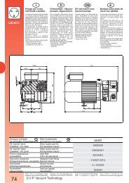
JET 61 - JET 61 M-P - GARDENJET 61<br />
JET 81 - JET 81 M-P - GARDENJET 81<br />
JET 100 - JET 100 M-P - GARDENJET 100<br />
JET 200 - JET 300<br />
DP 80 - DP 81 - DP 100<br />
DP 151 convertibili - DP 251 convertibili<br />
JET 151 convertibili - JET 251 convertibili<br />
NOVAGARDEN<br />
JETINOX 90 - JETINOX 110<br />
JETINOX 90 M-P - JETINOX 110 M-P<br />
GARDEN-INOX 90 M - GARDEN-INOX 110 M<br />
K-INOX 30/30 - K-INOX 30/30 M-P<br />
EURO 25/30 - EURO 30/30 - EURO 40/30<br />
EUROINOX 25/30 - EUROINOX 30/30 - EUROINOX 40/30<br />
EURO 30/50 - EURO 40/50 - EURO 50/50<br />
EUROINOX 30/50 - EUROINOX 40/50 - EUROINOX 50/50<br />
EURO 25/80 - EURO 30/80 - EURO 40/80<br />
EUROINOX 25/80 - EUROINOX 30/80 - EUROINOX 40/80<br />
K 20/41 -K 30/70 - K 30/100 - K 36/100<br />
K 12/200 - K 14/400<br />
K 35/40 - K 45/50 - K 55/50<br />
K 35/100 - K 40/100<br />
KP 30/16 – KP 38/18 - KP 60/6 - KP 60/12 - KPA 40/20
DICHIARAZIONE DI CONFORMITÀ<br />
La Ditta DAB <strong>PUMPS</strong> s.p.a. - Via M. Polo,14 -<br />
Mestrino (PD) - ITALY - sotto la propria esclusiva<br />
responsabilità dichiara che i prodotti summenzionati<br />
sono conformi a:<br />
− Direttiva del Consiglio del 14 giugno 1989 n° 89/392<br />
concernente il riavvicinamento delle legislazioni degli<br />
Stati membri CEE relative alle macchine e successive<br />
modifiche.<br />
− Direttiva della Compatibilità elettromagnetica 89/336<br />
e successive modifiche.<br />
− Direttiva Bassa Tensione 73/23 e successive<br />
modifiche.<br />
DECLARATION OF CONFORMITY<br />
The Company DAB <strong>PUMPS</strong> s.p.a. - Via M. Polo,14 -<br />
Mestrino (PD) - ITALY - declares under its own<br />
responsibility that the above-mentioned products comply<br />
with:<br />
− Council Directive no. 89/392 of 14 June 1989<br />
concerning the reconciliation of the legislations of<br />
EEC Member Countries with relation to machines<br />
and subsequent modifications .<br />
− Directive on electromagnetic compatibility no.<br />
89/336 and subsequent modifications .<br />
− Directive on low voltage no. 73/23 and subsequent<br />
modifications .<br />
CONFORMITEITSVERKLARING<br />
De firma DAB <strong>PUMPS</strong> s.p.a. - Via M. Polo, 14 Mestrino<br />
(PD) - Italië, verklaart hierbij onder haar verantwoording<br />
dat hierbovengenoemde produkten conform zijn aan<br />
− de Richtlijn van de Raad van 14 juni 1989 nr. 89/372<br />
betreffende harmonisatie van de wetgeving in de EEGlidstaten<br />
t.a.v. machines en daaropvolgende<br />
wijzigingen.<br />
− De richtlijnen van de elektromagnetische<br />
overeenstemming 89/336 en latere veranderingen.<br />
− De richtlijnen voor lage druk 73/23 en latere<br />
veranderingen.<br />
FÖRSÄKRAN OM ÖVERENSSTÄMMELSE<br />
Bolaget DAB <strong>PUMPS</strong> s.p.a. - Via M. Polo,14 -<br />
Mestrino (PD) - ITALIEN - intygar på eget ansvar att<br />
ovannämnda produkter är i enlighet med:<br />
− Rådets direktiv av den 14 juni 1989 nr. 89/392 och<br />
efterföljande ändringar som innehåller en jämkning<br />
av EU-ländernas lagstiftning beträffande maskiner.<br />
− EMC-direktivet nr. 89/336 och efterföljande<br />
ändringar.<br />
− Lågspänningsdirektiv nr. 73/23 och efterföljande<br />
ändringar.<br />
Mestrino (PD), 07 Gennaio 1998<br />
DÈCLARATION DE CONFORMITÈ<br />
L'entreprise DAB <strong>PUMPS</strong> s.p.a. - Via M. Polo,14 -<br />
Mestrino (PD) - ITALIE - déclare sous sa responsabilité<br />
exclusive que les produits susmentionnés sont conformes<br />
à:<br />
− la Directive du Conseil du 14 juin 1989 n° 89/392<br />
concernant l'harmonisation des législations des Etats<br />
membres de la CEE relatives aux machines et ses<br />
modifications successives .<br />
− la Directive de la compatibilité électromagnétique<br />
89/336 et ses modifications successives .<br />
− la Directive basse tension 73/23 et ses modifications<br />
successives.<br />
KONFORMITÄTSERKLÄRUNG<br />
Die Firma DAB <strong>PUMPS</strong> s.p.a. - Via M. Polo,14 -<br />
Mestrino (PD) - ITALY - erklärt unter ihrer eigenen,<br />
ausschließlichen Verantwortung, daß die genannten<br />
Produkte den folgenden Verordnungen entsprechen:<br />
− Ratsverordnung Nr. 89/392 vom 14. Juni 1989 über die<br />
Angleichung der Gesetzgebung der CEE-Staaten über<br />
Maschinen und folgende Abänderungen<br />
− Verordnung über die elektromagnetische Kompatibilität<br />
89/336 und folgende Abänderungen.<br />
− Verordnung über Schwachstrom 73/23 und folgende<br />
Abänderungen.<br />
DECLARACION DE CONFORMIDAD<br />
La Empresa DAB <strong>PUMPS</strong> s.p.a. - Via M. Polo,14 -<br />
Mestrino (PD) - ITALY - bajo su propia y exclusiva<br />
responsabilidad declara que los productos anteriormente<br />
mencionados respetan:<br />
− Las Directrices del Consejo del 14 de junio de 1989 n°<br />
89/392 referentes a la homogeneización de las<br />
legislaciones de los Estados miembros de la CEE<br />
relativas a las máquinas y sucesivas modificaciones<br />
− Directriz de la Compatibilidad electromagnética 89/336<br />
y sucesivas modificaciones<br />
− Directriz Baja Tensión 73/23 y sucesivas<br />
modificaciones<br />
UYGUNLUK BEYANI<br />
Via M. Polo, 14 – Mestrino (PD) –İTALYA’da bulunan<br />
DAB <strong>PUMPS</strong> S.p.A., kendi sorumluluğunu üstüne alarak<br />
yukarõda belirtilen ürünlerin<br />
- AET üyelerinin makinelerle ilgili normlar ile ilişkin<br />
tamamlamalarõnõn uyumlaştõrõlmasõna ait olan 14<br />
haziran 1989 tarihli, 89/392 sayõlõ Avrupa Konseyi<br />
Yönetmeliğine<br />
- 89/336 sayõlõ AET Elektromanyetik Uyum<br />
Yönetmeliği ile ilişkin tamamlamalarõna<br />
- 73/23 sayõlõ AET Alçak Gerilim Yönetmeliği ile<br />
ilişkin tamamlamalarõna uygun olduklarõnõ beyan eder.<br />
Attilio Conca<br />
Legale Rappresentante<br />
Legal Representative
4.<br />
ENGLISH<br />
The machine has been designed and built for pumping water, free from explosive<br />
substances and solid particles or fibres, with a density of 1000 kg/m³ and a<br />
kinematic viscosity of 1 mm²/s, and chemically non-aggressive liquids.<br />
TECHNICAL DATA AND RANGE OF USE<br />
− Supply voltage: 220 - 240V 50Hz<br />
110V 50Hz<br />
115V 60Hz<br />
230V 60Hz<br />
230 V3 – 400 V3 50/60Hz<br />
see electrical data plate<br />
− Absorbed power: see electrical data plate<br />
− Delivery: from 0,06 to 37 m 3 /h<br />
− Head up: to 102 m.<br />
− Pumped liquid: clean, free from solid bodies or abrasive substances, non-aggressive.<br />
− Degree of motor protection:<br />
IP44 (For IP55 see plate on package)<br />
− Degree of terminal board protection: IP55 (IP44 for KP 30/16)<br />
− Protection class:<br />
F<br />
− Cable clamp:<br />
PG 11 and/or PG 13.5, depending on models<br />
− Line fuses AM class:<br />
Model<br />
15<br />
110V 50Hz<br />
115V 60Hz<br />
Line fuses(Amps)<br />
220-240V 50Hz<br />
230V 60Hz<br />
230 V3<br />
50/60Hz<br />
400 V3<br />
50/60Hz<br />
KP 30/16; KP 30/16 Pred.; NOVAGARDEN 6 4 2 2<br />
KP 38/18; KP 38/18 Pred.; KP 60/6; JET 61; JET 61 M-P.; DP 81;<br />
GARDENJET 61; JET 81; JET 81 M-P.; GARDENJET 81; K 20/41;<br />
8 4 4 2<br />
JETINOX 90; JETINOX 90 M-P; GARDEN-INOX 90 M;<br />
K-INOX 30/30; K-INOX 30/30 M-G.; KPA 40/20 ;<br />
8 6 4 2<br />
KP 60/12; - - 6 4 4<br />
EURO-EUROINOX 40/30 – 30/50 – 25/80; 10 6 4 4<br />
EURO-EUROINOX 25/30 – 30/30; 8 4 4 4<br />
EURO-EUROINOX 40/50 – 30/80; 12 6 6 4<br />
EURO-EUROINOX 50/50 – 40/80; 20 8 6 4<br />
DP 80; 12 6 4 2<br />
JET 100; JET 100 M-P; GARDENJET 100; K 12/200; K 30/70;<br />
K 35/40; DP 100;<br />
12 6 6 4<br />
JETINOX 110; JETINOX 110 M-P; GAREDEN-INOX 110 M;<br />
K 30/100;<br />
16 8 6 4<br />
JET 151; K 35/100; 20 10 6 4<br />
K 40/100; K 36/100; K45/50; DP 151; 20 10 8 4<br />
JET 200; K 14/400; 20 10 8 6<br />
JET 251; 25 12 8 6<br />
JET 300; K 55/50; DP 251; 32 16 10 6<br />
Maximun operating pressure: 4,5 bar (450 kPa): NOVAGARDEN<br />
6 bar (600 kPa): JET 61, JET 81, JET 100 and derived; K-INOX 30/30<br />
and derived; KP 30/16; DP 80; DP 81; DP 100; EURO;<br />
EUROINOX and derived; K 35/40;K 35/100; K 40/100;<br />
K 20/41; K 30/70; K 30/100; K 36/100; K 12/200;<br />
K 14/400;<br />
7,5 bar (750 kPa): JET 151, JET 251; JET 200; JET 300; DP 151; DP 251;<br />
8 bar (800 kPa): JETINOX 90, JETINOX 110 and derived;<br />
K 45/50; K 55/50;<br />
10 bar (1000 kPa): KP 60/6; KP 60/12; KPA 40/20 ; KP 38/18<br />
Liquid temperature range: 0 ÷ +35°C: For all homologated pumps<br />
EN 60335-2-41 (for domestic uses)<br />
0 ÷ +40°C: JET 151, JET 251, JET 200, JET 300, DP 80, DP 81,<br />
DP 100, DP 151, DP 251,<br />
-10 ÷ +50°C: K 20/41, K 30/70, K 30/100, K 36/100, K 12/200,
ENGLISH<br />
K 35/40, K 45/50, K 35/100, K 40/100; KP 30/16; KP38/18<br />
-10 ÷ +80°C: KP 60/6, KP 60/12 ; KPA 40/20 ;<br />
-15 ÷ +110°C: K 14/400, K 55/50,<br />
− Storage temperature:<br />
-10°C to +40°C<br />
− Relative humidity of the air:<br />
MAX. 95%<br />
− Noise level:<br />
Falls within the limits envisaged by EC Directive<br />
89/392/EEC and subsequent modifications.<br />
− Motor construction in conformity with standards CEI 2-3 - CEI 61-69 (EN 60335-2-41)<br />
5. MANAGEMENT<br />
5.1 Storage<br />
All the pumps must be stored indoors, in a dry, vibration-free and dust-free environment, possibly with<br />
constant air humidity.<br />
They are supplied in their original packaging and must remain there until the time of installation. If this is<br />
not possible, the intake and delivery aperture must be accurately closed.<br />
5.2 Transport<br />
Avoid subjecting the products to needless jolts or collisions.<br />
To lift and transport the unit, use lifting equipment and the pallet supplied standard (if applicable).<br />
5.3 Weights<br />
The adhesive label on the package indicates the total weight of the electropump.<br />
6. WARNINGS<br />
6.1 Skilled technical personnel<br />
It is advisable that installation be carried out by skilled personnel in<br />
possession of the technical qualifications required by the specific<br />
legislation in force.<br />
The term skilled personnel means persons whose training, experience and instruction, as well<br />
as their knowledge of the respective standards and requirements for accident prevention and<br />
working conditions, have been approved by the person in charge of plant safety, authorizing<br />
them to perform all the necessary activities, during which they are able to recognize and avoid<br />
all dangers. (Definition for technical personnel IEC 364).<br />
6.2 Safety<br />
Use is allowed only if the electric system is in possession of safety precautions in accordance with the<br />
regulations in force in the country where the product is installed (for Italy, CEI 64/2).<br />
6.3 Checking motor shaft rotation<br />
Before installing the pump you must check that the rotating parts turn freely. For this purpose remove the<br />
fan cover (13) from its seat in the motor end cover (11). Insert a screwdriver in the notch on the motor shaft<br />
from the ventilation side. If there is a blockage, turn the screwdriver, tapping it gently with a hammer. FIG.<br />
A<br />
6.4 Responsibility<br />
The Manufacturer does not vouch for correct operation of the pumps if they are<br />
tampered with or modified, run outside the recommended work range or in contrast with<br />
the other instructions given in this manual.<br />
7.<br />
The Manufacturer declines all responsibility for possible errors in this instructions<br />
manual, if due to misprints or errors in copying. The company reserves the right to<br />
make any modifications to products that it may consider necessary or useful, without<br />
affecting the essential characteristics.<br />
INSTALLATION<br />
7.1 The electropump must be fitted in a well ventilated place, protected from unfavourable weather<br />
conditions and with an environment temperature not exceeding 40°C. Fig.B<br />
7.2 A firm anchoring of the pump to the bearing surface favours the absorption of any vibrations<br />
caused by pump operation. Fig. C<br />
7.3 Ensure that the metal pipes do not exert undue strain on the apertures, thus preventing<br />
deformations or breakages. Fig. C<br />
7.4 It is always good practice to place the pump as close as possible to the liquid to be pumped.<br />
The pump must be installed only in horizontal position. The internal diameters of the pipes must<br />
16
ENGLISH<br />
never be smaller than that of the mouth of the electropump. It is advisable to fit a foot valve on<br />
suction. Fig. D For suction depths of over four metres or with long horizontal stretches it is<br />
advisable to use an intake hose with a diameter larger than that of the intake aperture of the pump.<br />
To prevent the formation of air pockets, the intake hose must slope slightly upwards towards the<br />
pump. Fig. D<br />
7.5 If the intake pipe is made of rubber or flexible material, always check that it is of the reinforced<br />
type to avoid throttling due to suction.<br />
7.6 NOVAGARDEN electropumps must be connected to the pipe exclusively by means of flexible<br />
couplings so that the weight of the pipes does not bear down on the pump.<br />
7.7 The lifting and carrying handle must always be present and well fixed to the support on all<br />
pumps produced in the portable version.<br />
8. ELECTRICAL CONNECTION<br />
Caution! always follow the safety regulations.<br />
Scrupulously follow the wiring diagrams inside the terminal board<br />
box.<br />
8.1 Electric installation must be carried out by skilled and authorized electrician who accepts<br />
all the responsibility for the job.<br />
8.2 Ensure that the mains voltage is the same as the value shown on the motor plate and that there is<br />
the possibility of MAKING A GOOD EARTH CONNECTION. Fig. E<br />
8.3 In fixed installations, International Safety Standards require the use of isolating switches with a<br />
fuse-carrier base.<br />
8.4 Single-phase motors are provided with built-in thermal overload protection and may be connected<br />
directly to the mains. Three-phase motors must be protected with special remote-control motorprotectors<br />
calibrated for the current shown on the plate.<br />
9. STARTING UP<br />
9.1<br />
Do not start the pump unless it has been completely filled with<br />
fluid.<br />
Before starting up, check that the pump is properly primed; fill it completely with clean water by<br />
means of the hole provided after having removed the filler cap on the pump body. This ensures<br />
that the mechanical seal is well lubricated and that the pump immediately starts to work regularly.<br />
(Fig. F). Dry operation causes irreparable damage to the mechanical seal. The filling cap<br />
must then be screwed back on carefully.<br />
9.2 Switch on the power and check, on the three-phase version, that the motor is turning in the correct<br />
direction; this should be in a clockwise direction, looking at the motor from the impeller side. Fig.<br />
G If it is turning in the wrong direction, invert the connections of any two wires on the terminal<br />
board, after having disconnected the pump from the power mains.<br />
10. PRECAUTIONS<br />
10.1 The electropump should not be started more than 20 times in one hour so as not to subject the<br />
motor to excessive thermal shock.<br />
10.2 DANGER OF FROST: When the pump remains inactive for a long time at temperatures of less<br />
than 0°C, the pump body must be completely emptied through the drain cap (26) Fig. H, to<br />
prevent possible cracking of the hydraulic components. This operation is advisable even in the<br />
event of prolonged inactivity at normal temperature.<br />
10.3 When starting after long periods of inactivity, the starting-up operations listed above must be<br />
repeated.<br />
11. MAINTENANCE AND CLEANING<br />
In normal operation, the pump does not require any specific maintenance. However,<br />
it may be necessary to clean the hydraulic parts when a fall in yield is observed. The<br />
electropump must not be dismantled unless by skilled personnel in possession of<br />
the qualifications required by the regulations in force. In any case, all repairs and<br />
17
ENGLISH<br />
maintenance jobs must be carried out only after having disconnected the pump from<br />
the power mains.<br />
12. MODIFICATIONS AND SPARE PARTS<br />
Any modification not authorized beforehand relieves the manufacturer of all<br />
responsibility. All the spare parts used in repairs must be original ones and the<br />
accessories must be approved by the manufacturer so as to be able to guarantee<br />
maximum safety of the machines and systems in which they may be fitted.<br />
In the event of damage to the power cable of this appliance, the repair<br />
must be carried out by skilled personnel, in order to prevent all risks.<br />
12.1 Removal and replacement of the supply cable<br />
Before starting, ensure that the electropump is not connected to the power network.<br />
A) For versions without a pressure switch<br />
Remove the condenser cover (92), unscrewing the four screws (53) on it. Unscrew the three terminals L<br />
- N - and disconnect the brown lead, the blue lead and the yellow-green lead, coming from the supply<br />
cable, after having slackened the grommet (84).<br />
B) For versions with a SQUARE D pressure switch<br />
− Section of cable with plug from the pressure switch: unscrew the screw from the cover of the pressure<br />
switch using a screwdriver and remove the cover. Remove the yellow-green lead, slackening the earth<br />
screw, the blue lead and the brown lead from the respective terminals at the side, slackening the screws<br />
on the terminals. Remove the cable blocking terminal, slackening the respective screws, and slip off the<br />
cable which is now disconnected.<br />
− Section of cable from the pressure switch to the terminal board: unscrew the nut from the cover of<br />
the pressure switch using a screwdriver and remove the cover. Remove the yellow-green lead,<br />
slackening the earth screw, the blue lead and the brown lead from the respective central terminals,<br />
slackening the screws on the terminals. Remove the cable blocking terminal, slackening the respective<br />
screws, and slip off the cable which is now disconnected. Remove the condenser cover (92), unscrewing<br />
the four screws (53) on it. Unscrew the three terminals L - N -<br />
18<br />
and disconnect the brown lead, the blue<br />
lead and the yellow-green lead, coming from the pressure switch, after having slackened the grommet<br />
(84).<br />
C) Version with a TELEMECANIQUE / SQUARE D – TELEMECANIQUE / ITALTECNICA<br />
pressure switch:<br />
− Section of cable with plug from the pressure switch: unscrew the screw from the cover of the pressure<br />
switch using a screwdriver and remove the cover, releasing it from the base of the pressure switch. Slip<br />
out the yellow-green lead, unscrewing the earth screw on the left side. Still on the same side, slip the<br />
blue lead and the brown lead off their terminals, slackening the screws on the terminals. Slacken the<br />
cable clamping nut of the pressure switch on the left side and slip off the cable which is now<br />
disconnected.<br />
− Section of cable from the pressure switch to the terminal board: unscrew the nut on the cover of the<br />
pressure switch using a screwdriver and remove the cover, releasing it from the base of the pressure<br />
switch. Slip out the yellow-green lead, unscrewing the earth screw on the right side. Still on the same<br />
side, slip the blue lead and the brown lead off their terminals, slackening the screws on the terminals.<br />
Slacken the cable clamping nut of the pressure switch on the right side and slip off the cable which is<br />
now disconnected. Remove the terminal board cover (92), unscrewing the four screws (53) on it.<br />
Unscrew the three terminals L - N - and disconnect the brown lead, the blue lead and the yellow-green<br />
lead, coming from the supply pressure switch, after having slackened the grommet (84).<br />
When replacing the power cable, a cable of the same type must be used (e.g. H05 RN-F or H07 RN-F<br />
depending on the installation) and with the same terminals, proceeding as for disassembly in inverse<br />
order.
ENGLISH<br />
ATTENTION: depending on the installation and if the pumps have no cable, fit supply cables type<br />
H05 RN-F for indoor use and type H07 RN-F for outdoor use, complete with plug (standards 61-69).<br />
For power cables without a plug, provide a device for cutting off the mains (e.g. magnetothermal<br />
device) with separating contacts of at least 3 mm for each pole.<br />
13. TROUBLESHOOTING<br />
FAUL CHECKS (possible cause) REMEDY<br />
1. The motor does not<br />
start and makes no<br />
noise<br />
2. The motor does not<br />
start but makes noise.<br />
3. The motor turns with<br />
difficulty.<br />
4. The pump does not<br />
deliver.<br />
5. The pump does not<br />
prime.<br />
6. The pump supplies<br />
insufficient flow.<br />
7. The pump vibrates<br />
and operates noisily.<br />
A. Check the electric connections.<br />
B. Check that the motor is live.<br />
C. Check the protection fuses.<br />
A. Ensure that the mains voltage is the same<br />
as the value on the plate.<br />
B. Ensure that the connections have been<br />
made correctly.<br />
C. Check that all the phases are present on<br />
the terminal board. (3~)<br />
D. Look for possible blockages in the pump<br />
or motor.<br />
E. Check the condition of the capacitor.<br />
A. Check the voltage which may be<br />
insufficient.<br />
B. Check whether any moving parts are<br />
scraping against fixed parts.<br />
A. The pump has not been primed correctly.<br />
B. On three-phase motors, check that the<br />
direction of rotation is correct.<br />
C. The diameter of the intake pipe is<br />
insufficient.<br />
D. Blocked foot valve.<br />
A. The intake pipe or the foot valve is taking<br />
in air.<br />
B. The downward slope of the intake pipe<br />
favours the formation of air pockets.<br />
A. Blocked foot valve.<br />
B. The impeller is worn or blocked.<br />
C. The diameter of the intake pipe is<br />
insufficient.<br />
D. On three-phase motors, check that the<br />
direction of rotation is correct.<br />
A. Check that the pump and the pipes are<br />
firmly anchored.<br />
B. There is cavitation in the pump, that is the<br />
demand for water is higher than it is able<br />
to pump.<br />
C. The pump is running above its plate<br />
characteristics.<br />
19<br />
C. If they are burnt-out, change them.<br />
N.B. If the fault is repeated immediately this<br />
means that the motor is short circuiting.<br />
B. Correct any errors.<br />
C. If not, restore the missing phase.<br />
D. Remove the blockage.<br />
E. Replace the capacitor.<br />
B. Eliminate the cause of the scraping.<br />
B. If necessary, invert the connection of two<br />
supply wires<br />
C. Replace the pipe with one with a larger<br />
diameter.<br />
D. Clean the foot valve.<br />
A. Eliminate the phenomenon and prime<br />
again.<br />
B. Correct the inclination of the intake pipe.<br />
A. Clean the foot valve.<br />
B. Remove the obstructions or replace the<br />
worn parts.<br />
C. Replace the pipe with one with a larger<br />
diameter.<br />
D. If necessary, invert the connection of two<br />
supply wires<br />
A. Fix the loose parts more carefully.<br />
B. Reduce the intake height or check for<br />
load losses.<br />
C. It may be useful to limit the flow at<br />
delivery.