MAX8640Y - Maxim
MAX8640Y - Maxim
MAX8640Y - Maxim

You also want an ePaper? Increase the reach of your titles
YUMPU automatically turns print PDFs into web optimized ePapers that Google loves.
RELIABILITY REPORT FOR<br />
<strong>MAX8640Y</strong>/ZEXT24+<br />
MAX8640ZEXT24+<br />
PLASTIC ENCAPSULATED DEVICES<br />
February 10, 2009<br />
MAXIM INTEGRATED PRODUCTS<br />
120 SAN GABRIEL DR.<br />
SUNNYVALE, CA 94086<br />
Approved by<br />
Ken Wendel<br />
Quality Assurance<br />
Director, Reliability Engineering<br />
<strong>MAX8640Y</strong>/ZEXT24+<br />
<strong>Maxim</strong> Integrated Products. All rights reserved. Page 1/5
Conclusion<br />
The <strong>MAX8640Y</strong>/ZEXT24+ successfully meets the quality and reliability standards required of all <strong>Maxim</strong> products. In addition,<br />
<strong>Maxim</strong>"s continuous reliability monitoring program ensures that all outgoing product will continue to meet <strong>Maxim</strong>"s quality and reliability<br />
standards.<br />
Table of Contents<br />
I. ........Device Description V. ........Quality Assurance Information<br />
II. ........Manufacturing Information VI. .......Reliability Evaluation<br />
III. .......Packaging Information IV. .......Die Information<br />
.....Attachments<br />
I. Device Description<br />
A. General<br />
<strong>MAX8640Y</strong>/ZEXT24+<br />
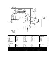
The <strong>MAX8640Y</strong>/MAX8640Z step-down converters are optimized for applications where small size, high efficiency, and low output ripple are priorities.<br />
They utilize a proprietary PWM control scheme that optimizes the switching frequency for high efficiency with small external components and<br />
maintains low output ripple voltage at all loads. The MAX8640Z switches at up to 4MHz to allow a tiny 1µH inductor and 2.2µF output capacitor. The<br />
<strong>MAX8640Y</strong> switches at up to 2MHz for higher efficiency while still allowing small 2.2µH and 4.7µF components. Output current is guaranteed up to<br />
500mA, while typical quiescent current is 28µA. Factory-preset output voltages from 0.8V to 2.5V eliminate external feedback components. Internal<br />
synchronous rectification greatly improves efficiency and replaces the external Schottky diode required in conventional step-down converters. Internal<br />
fast soft-start eliminates inrush current so as to reduce input capacitor requirements. The <strong>MAX8640Y</strong>/MAX8640Z are available in the tiny 6-pin, SC70<br />
(2.0mm x 2.1mm) and µDFN (1.5mm x 1.0mm) packages. Both packages are lead-free.<br />
<strong>Maxim</strong> Integrated Products. All rights reserved. Page 2/5
II. Manufacturing Information<br />
A. Description/Function: Tiny 500mA, 4MHz/2MHz Synchronous Step-Down DC-DC Converters<br />
B. Process: S4<br />
C. Number of Device Transistors:<br />
D. Fabrication Location: Texas<br />
E. Assembly Location: Carsem Malaysia, UTL Thailand<br />
F. Date of Initial Production: August 18, 2006<br />
III. Packaging Information<br />
A. Package Type: 6-pin SC70<br />
B. Lead Frame: Cu Alloy<br />
C. Lead Finish: 100% matte Tin<br />
D. Die Attach: Non Conductive Epoxy<br />
E. Bondwire: Au (1.3 mil dia.)<br />
F. Mold Material: Epoxy with silica filler<br />
G. Assembly Diagram: #<br />
H. Flammability Rating: Class UL94-V0<br />
I. Classification of Moisture Sensitivity per<br />
JEDEC standard J-STD-020-C<br />
Level 1<br />
IV. Die Information<br />
J. Single Layer Theta Ja: 326°C/W<br />
K. Single Layer Theta Jc: 115°C/W<br />
A. Dimensions: 32 X 31 mils<br />
B. Passivation: Si3N4/SiO2 (Silicon nitride/ Silicon dioxide<br />
C. Interconnect: Aluminum/Si (Si = 1%)<br />
D. Backside Metallization: None<br />
E. Minimum Metal Width: Metal1 = 0.5 / Metal2 = 0.6 / Metal3 = 0.6 microns (as drawn)<br />
F. Minimum Metal Spacing: Metal1 = 0.45 / Metal2 = 0.5 / Metal3 = 0.6 microns (as drawn)<br />
G. Bondpad Dimensions: 5 mil. Sq.<br />
H. Isolation Dielectric: SiO2<br />
I. Die Separation Method: Wafer Saw<br />
<strong>MAX8640Y</strong>/ZEXT24+<br />
<strong>Maxim</strong> Integrated Products. All rights reserved. Page 3/5
V. Quality Assurance Information<br />
A. Quality Assurance Contacts: Ken Wendel (Director, Reliability Engineering)<br />
Bryan Preeshl (Managing Director of QA)<br />
B. Outgoing Inspection Level: 0.1% for all electrical parameters guaranteed by the Datasheet.<br />
0.1% For all Visual Defects.<br />
C. Observed Outgoing Defect Rate: < 50 ppm<br />
D. Sampling Plan: Mil-Std-105D<br />
VI. Reliability Evaluation<br />
A. Accelerated Life Test<br />
<strong>MAX8640Y</strong>/ZEXT24+<br />
The results of the 135°C biased (static) life test are shown in Table 1. Using these results, the Failure Rate ( ) is calculated as<br />
follows:<br />
= 1 = 1.83 (Chi square value for MTTF upper limit)<br />
MTTF 192 x 4340 x 44 x 2<br />
(where 4340 = Temperature Acceleration factor assuming an activation energy of 0.8eV)<br />
= 24.4 x 10 -9<br />
= 24.4 F.I.T. (60% confidence level @ 25°C)<br />
The following failure rate represents data collected from <strong>Maxim</strong>’s reliability monitor program. <strong>Maxim</strong> performs quarterly 1000<br />
hour life test monitors on its processes. This data is published in the Product Reliability Report found at http://www.maxim-ic.com/.<br />
Current monitor data for the S4 Process results in a FIT Rate of 4.6 @ 25C and 79.2 @ 55C (0.8 eV, 60% UCL)<br />
B. Moisture Resistance Tests<br />
The industry standard 85°C/85%RH or HAST testing is monitored per device process once a quarter.<br />
C. E.S.D. and Latch-Up Testing<br />
The PN82 die type has been found to have all pins able to withstand a HBM transient pulse of +/-2500 V per JEDEC<br />
JESD22-A114-D. Latch-Up testing has shown that this device withstands a current of +/-200 mA.<br />
<strong>Maxim</strong> Integrated Products. All rights reserved. Page 4/5
TEST ITEM TEST CONDITION FAILURE<br />
IDENTIFICATION<br />
Static Life Test (Note 1)<br />
Ta = 135°C<br />
Biased<br />
Time = 192 hrs.<br />
Moisture Testing (Note 2)<br />
85/85 Ta = 85°C<br />
RH = 85%<br />
Biased<br />
Time = 1000hrs.<br />
Mechanical Stress (Note 2)<br />
Temperature<br />
Cycle<br />
-65°C/150°C<br />
1000 Cycles<br />
Method 1010<br />
DC Parameters<br />
& functionality<br />
DC Parameters<br />
& functionality<br />
DC Parameters<br />
& functionality<br />
Note 1: Life Test Data may represent plastic DIP qualification lots.<br />
Note 2: Generic Package/Process data<br />
Table 1<br />
Reliability Evaluation Test Results<br />
<strong>MAX8640Y</strong>/ZEXT24+<br />
SAMPLE SIZE NUMBER OF<br />
FAILURES<br />
44 0<br />
77 0<br />
77 0<br />
<strong>MAX8640Y</strong>/ZEXT24+<br />
<strong>Maxim</strong> Integrated Products. All rights reserved. Page 5/5