POWER AMPLIFIER
POWER AMPLIFIER
POWER AMPLIFIER

You also want an ePaper? Increase the reach of your titles
YUMPU automatically turns print PDFs into web optimized ePapers that Google loves.
XP7000/XP5000<br />
■ DISASSEMBLY PROCEDURES <br />
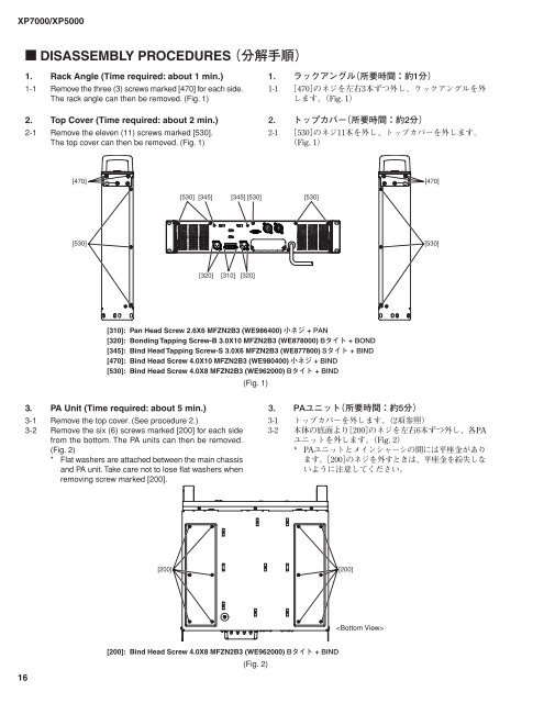
1. Rack Angle (Time required: about 1 min.)<br />
1-1 Remove the three (3) screws marked [470] for each side.<br />
The rack angle can then be removed. (Fig. 1)<br />
2. Top Cover (Time required: about 2 min.)<br />
2-1 Remove the eleven (11) screws marked [530].<br />
The top cover can then be removed. (Fig. 1)<br />
<br />
<br />
<br />
<br />
<br />
<br />
<br />
<br />
<br />
<br />
[470] [470]<br />
[530] [345]<br />
[345] [530]<br />
[530]<br />
[530]<br />
[530]<br />
[320] [310] [320]<br />
[310]: Pan Head Screw 2.6X6 MFZN2B3 (WE986400) <br />
[320]: Bonding Tapping Screw-B 3.0X10 MFZN2B3 (WE878000) <br />
[345]: Bind Head Tapping Screw-S 3.0X6 MFZN2B3 (WE877800) <br />
[470]: Bind Head Screw 4.0X10 MFZN2B3 (WE980400) <br />
[530]: Bind Head Screw 4.0X8 MFZN2B3 (WE962000) <br />
(Fig. 1)<br />
3. PA Unit (Time required: about 5 min.)<br />
3-1 Remove the top cover. (See procedure 2.)<br />
3-2 Remove the six (6) screws marked [200] for each side<br />
from the bottom. The PA units can then be removed.<br />
(Fig. 2)<br />
* Flat washers are attached between the main chassis<br />
and PA unit. Take care not to lose flat washers when<br />
removing screw marked [200].<br />
<br />
<br />
<br />
<br />
<br />
<br />
<br />
<br />
<br />
<br />
[200] [200]<br />
<br />
16<br />
[200]: Bind Head Screw 4.0X8 MFZN2B3 (WE962000) <br />
(Fig. 2)