POWER AMPLIFIER
POWER AMPLIFIER
POWER AMPLIFIER

You also want an ePaper? Increase the reach of your titles
YUMPU automatically turns print PDFs into web optimized ePapers that Google loves.
XP7000/XP5000<br />
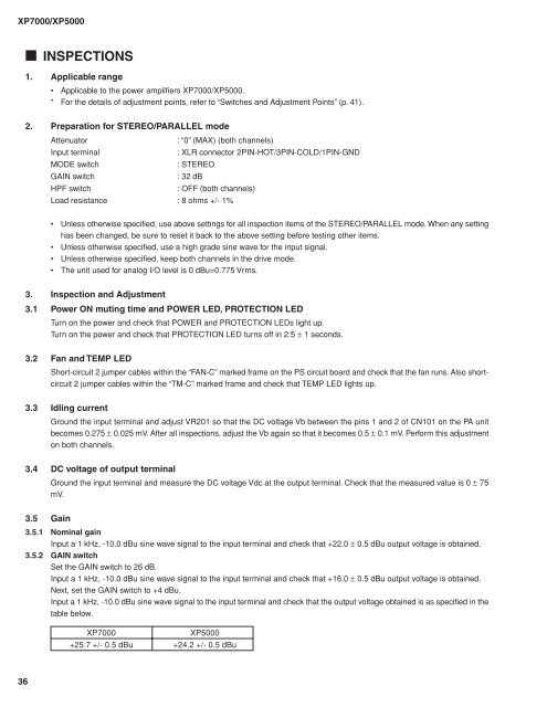
■ INSPECTIONS<br />
1. Applicable range<br />
• Applicable to the power amplifiers XP7000/XP5000.<br />
* For the details of adjustment points, refer to “Switches and Adjustment Points” (p. 41).<br />
2. Preparation for STEREO/PARALLEL mode<br />
Attenuator<br />
: “0” (MAX) (both channels)<br />
Input terminal<br />
: XLR connector 2PIN-HOT/3PIN-COLD/1PIN-GND<br />
MODE switch<br />
: STEREO<br />
GAIN switch<br />
: 32 dB<br />
HPF switch<br />
: OFF (both channels)<br />
Load resistance : 8 ohms +/- 1%<br />
• Unless otherwise specified, use above settings for all inspection items of the STEREO/PARALLEL mode. When any setting<br />
has been changed, be sure to reset it back to the above setting before testing other items.<br />
• Unless otherwise specified, use a high grade sine wave for the input signal.<br />
• Unless otherwise specified, keep both channels in the drive mode.<br />
• The unit used for analog I/O level is 0 dBu=0.775 Vrms.<br />
3. Inspection and Adjustment<br />
3.1 Power ON muting time and <strong>POWER</strong> LED, PROTECTION LED<br />
Turn on the power and check that <strong>POWER</strong> and PROTECTION LEDs light up.<br />
Turn on the power and check that PROTECTION LED turns off in 2.5 ± 1 seconds.<br />
3.2 Fan and TEMP LED<br />
Short-circuit 2 jumper cables within the “FAN-C” marked frame on the PS circuit board and check that the fan runs. Also shortcircuit<br />
2 jumper cables within the “TM-C” marked frame and check that TEMP LED lights up.<br />
3.3 Idling current<br />
Ground the input terminal and adjust VR201 so that the DC voltage Vb between the pins 1 and 2 of CN101 on the PA unit<br />
becomes 0.275 ± 0.025 mV. After all inspections, adjust the Vb again so that it becomes 0.5 ± 0.1 mV. Perform this adjustment<br />
on both channels.<br />
3.4 DC voltage of output terminal<br />
Ground the input terminal and measure the DC voltage Vdc at the output terminal. Check that the measured value is 0 ± 75<br />
mV.<br />
3.5 Gain<br />
3.5.1 Nominal gain<br />
Input a 1 kHz, -10.0 dBu sine wave signal to the input terminal and check that +22.0 ± 0.5 dBu output voltage is obtained.<br />
3.5.2 GAIN switch<br />
Set the GAIN switch to 26 dB.<br />
Input a 1 kHz, -10.0 dBu sine wave signal to the input terminal and check that +16.0 ± 0.5 dBu output voltage is obtained.<br />
Next, set the GAIN switch to +4 dBu.<br />
Input a 1 kHz, -10.0 dBu sine wave signal to the input terminal and check that the output voltage obtained is as specified in the<br />
table below.<br />
XP7000<br />
+25.7 +/- 0.5 dBu<br />
XP5000<br />
+24.2 +/- 0.5 dBu<br />
36