("Golden Gnat" Rate Gyro \253 Edge Triggered)
("Golden Gnat" Rate Gyro \253 Edge Triggered)
("Golden Gnat" Rate Gyro \253 Edge Triggered)

Create successful ePaper yourself
Turn your PDF publications into a flip-book with our unique Google optimized e-Paper software.
5/26/2011 "<strong>Golden</strong> Gnat" <strong>Rate</strong> <strong>Gyro</strong> « <strong>Edge</strong> Trigger…<br />
<strong>Edge</strong> <strong>Triggered</strong><br />
An escapade with electricity at the precipice of sanity<br />
The <strong>Golden</strong> Gnat<br />
23 February 2010<br />
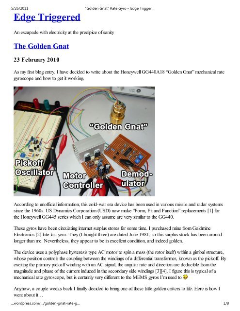
As my first blog entry, I have decided to write about the Honeywell GG440A18 “<strong>Golden</strong> Gnat” mechanical rate<br />
gyroscope and how to get it working.<br />
According to unofficial information, this cold-war era device has been used in various missile and radar systems<br />
since the 1960s. US Dynamics Corporation (USD) now make “Form, Fit and Function” replacements [1] for<br />
the Honeywell GG445 series which I can only assume are very similar to the GG440.<br />
These gyros have been circulating internet surplus stores for some time. I purchased mine from Goldmine<br />
Electronics [2] late last year. They (I bought three) are dated June 1981, so this surplus stock has been around<br />
longer than me. Nevertheless, they appear to be in excellent condition, and indeed golden.<br />
The device uses a polyphase hysteresis type AC motor to spin a mass (the rotor itself) within a gimbal structure,<br />
whose position controls the coupling between the windings of a differential transformer, known as the pickoff. By<br />
exciting the primary pickoff winding with an AC signal, the angular rate and direction are deducible from the<br />
magnitude and phase of the current induced in the secondary side windings [3][4]. I figure this is typical of a<br />
mechanical rate gyroscope, but is certainly very different to the MEMS gyros I’m used to<br />
Anyhow, a couple weeks back I finally decided to bring one of these little golden critters to life. Here is how I<br />
went about it…<br />
…wordpress.com/…/golden-gnat-rate-g… 1/8
5/26/2011 "<strong>Golden</strong> Gnat" <strong>Rate</strong> <strong>Gyro</strong> « <strong>Edge</strong> Trigger…<br />
Step 1: Getting the motor to spin.<br />
The gyro’s motor requires two AC bipolar drive signals separated by 90 degrees at presumably 400 Hz. As I<br />
happened to have a couple of STMicro’s L165 power op-amps at hand, I went ahead and built a simple directdrive<br />
sinusoidal quadrature oscillator for this purpose:<br />
You might be wondering why the six zener diodes The purpose of these is to prevent saturation of the<br />
waveform. I also happened to have exactly six 3 V zeners in my drawer at the time. Also note that resistor R8<br />
was added to initiate oscillation on power-up, and that the op-amp output snubber values were arbitrarily chosen<br />
and probably have no real significance.<br />
Not the most stable design in terms of frequency drift, but for a test circuit I was satisfied. I think the following<br />
screenshot speaks for itself:<br />
…wordpress.com/…/golden-gnat-rate-g… 2/8
5/26/2011 "<strong>Golden</strong> Gnat" <strong>Rate</strong> <strong>Gyro</strong> « <strong>Edge</strong> Trigger…<br />
Step 2: Exciting the pickoff.<br />
The primary winding of the pickoff is driven by a single phase AC signal. I couldn’t find any specifications for the<br />
Honeywell GG440’, so it was up to the generic guidance of USD documentation and a bit of experimentation to<br />
work out.<br />
Typically one would want to oscillate the pickoff at a frequency much higher than the response bandwidth of the<br />
gyro to avoid aliasing. I figured this would be maybe 50Hz at best, though highly unlikely. Additionally, the<br />
inherent cog-free (cogless, uncogful, without cog) motion of the hysteresis motor practically eliminates the<br />
impact of motor drive frequency on sampling error. With this in mind, and in my initial haste, I simply tapped off<br />
one of the motor drive phases to provide an excitation signal for the pickoff winding. This was simple and<br />
worked OK.<br />
By this stage I had already advanced to Step 3 by building a demodulator, so it was time to decide on an optimal<br />
frequency to drive the pickoff. It was an iterative process, and as you’ll find out, a 0 or 180 degree phase<br />
relationship between input and output was desirable in addition to maximizing the output signal swing.<br />
Equipped with a signal generator (my computer) and an amplifier, I was able to sweep through a range of<br />
frequencies up to 10 kHz while wiggling the gyroscope and monitoring the input-output response.<br />
Coincidentally, the largest magnitude response and suitable phase shift were both observed at about 1 kHz,<br />
without capacitive tuning. It was time to build a computer-free circuit:<br />
Here I have modified the typical op-amp based Wien bridge oscillator to provide a higher current output.<br />
Resistors R(1,2,3,4,10) and diodes D(1,2) adjust the output voltage swing and prevent op-amp saturation. C5<br />
provides the bulk of the output feedback, while R7 is to help with initial start-up. Resistors R(8,9) relieve the<br />
BJTs of excessive power dissipation by sharing some of the waste. Did I really need to say all that Am I<br />
…wordpress.com/…/golden-gnat-rate-g… 3/8
BJTs of excessive power dissipation by sharing some of the waste. Did I really need to say all that Am I<br />
rambling on too much<br />
5/26/2011 "<strong>Golden</strong> Gnat" <strong>Rate</strong> <strong>Gyro</strong> « <strong>Edge</strong> Trigger…<br />
The following screenshot shows the waveforms produced by this circuit while powering the primary pickoff coil:<br />
The visible periodic glitch is caused by a combination of the pickoff inductance and the limited speed at which the<br />
circuit can react to the dead-zone caused by the base-emitter junctions of the transistors. A snubber would<br />
alleviate this issue.<br />
Step 3: Demodulating the output.<br />
In order to report both magnitude and direction information of angular velocity, some kind of phase sensitive<br />
rectification of the pickoff output is required. This can be achieved by using a couple of bipolar transistors and a<br />
differential amplifier to work with the synchronized input and output waveforms of the pickoff:<br />
…wordpress.com/…/golden-gnat-rate-g… 4/8
5/26/2011 "<strong>Golden</strong> Gnat" <strong>Rate</strong> <strong>Gyro</strong> « <strong>Edge</strong> Trigger…<br />
(Adapted from [5])<br />
By studying this circuit, it becomes apparent that for the best results, i.e. maximum sensitivity, both the pickoff<br />
windings must be either in phase, or 180 degrees out of phase. A 90 degree separation is worst, but can be<br />
corrected for by using a lead or lag compensator on the pickoff primary sampling input. To show why an out of<br />
phase relationship is undesirable, compare in the following illustration, a normalized pickoff input (red), pickoff<br />
output (blue), and how the rectified difference (filled in green) affects the average output magnitude (purple):<br />
Referring back to the schematic, it is also worth noting that because BJTs have been used here for the<br />
…wordpress.com/…/golden-gnat-rate-g… 5/8
5/26/2011 "<strong>Golden</strong> Gnat" <strong>Rate</strong> <strong>Gyro</strong> « <strong>Edge</strong> Trigger…<br />
rectification, there will be some dead-zone around the waveform zero crossings, so the pickoff oscillator need<br />
not have perfect zero-crossing characteristics – something I hadn’t thought of at the time. The rest of the circuit is<br />
just offset nulling, some gain and some filtering.<br />
Results<br />
The output bandwidth of the demodulator is limited to about 3 Hz, so the time scale of the following graph<br />
covers 10 seconds to show the relevant information. Here I’ve tried to rotate the gyro by hand at a constant rate<br />
back and forth 180 degrees while pausing in between turns:<br />
From the rate output, it looks as though I’ve consumed too much coffee, but after integrating the output to give<br />
angular position, you can see that I didn’t do too badly after all. If this isn’t convincing enough, perhaps the<br />
following video will give a better idea of the response:<br />
…wordpress.com/…/golden-gnat-rate-g… 6/8
5/26/2011 "<strong>Golden</strong> Gnat" <strong>Rate</strong> <strong>Gyro</strong> « <strong>Edge</strong> Trigger…<br />
Final words<br />
Getting the GG400’ mechanical gyro to provide a useful, legible output is not a trivial task. While focusing on the<br />
basics, many design aspects such as stability, efficiency, and elegance were pushed aside. The motor controller<br />
works well in a test environment but suffers from drift, while the pickoff oscillator and demodulator could be<br />
combined and simplified. Maybe one day I’ll improve on these things, but for now I’m satisfied and I hope you<br />
are too.<br />
References<br />
1. US Dynamics Corporation, “<strong>Rate</strong> <strong>Gyro</strong>scopes: 475 Series”, US Dynamics Corporation, December 18,<br />
2006, [Online]. Available: http://www.usdynamicscorp.com/literature/general/475_series1.pdf [Accessed:<br />
February, 2010].<br />
2. Goldmine Electronics, “SALE! Missile <strong>Rate</strong> <strong>Gyro</strong>scope”, Goldmine Electronics, http://www.goldmineelec-products.com/prodinfo.aspnumber=G17270<br />
[Accessed: February, 2010].<br />
3. US Dynamics Corporation, “US Dynamics Model 475 Series <strong>Rate</strong> <strong>Gyro</strong>scope Technical Brief” (USD-<br />
AN-001), US Dynamics Corporation, December, 2005, [Online].<br />
http://www.usdynamics.org/whatsnew/news/USD%20News%20-<br />
%20US%20Dynamics%20<strong>Rate</strong>%20<strong>Gyro</strong>scope%20AN-0011.pdf [Accessed: February, 2010].<br />
4. US Dynamics Corporation, “Spinning Mass Mechanical <strong>Gyro</strong>scopes” (USD-AN-005), US Dynamics<br />
Corporation, August, 2006, [Online]. http://www.usdynamicscorp.com/literature/general/AN-<br />
005%20USD%20Spinning%20Mass%20<strong>Gyro</strong>scopes.pdf [Accessed: February, 2010].<br />
5. US Dynamics Corporation, “Basic Output Generator Excitation and Demodulation Requirements for US<br />
Dynamics Miniature <strong>Gyro</strong>scopes” (USD-AN-004), US Dynamics Corporation, August, 2006, [Online].<br />
http://www.usdynamicscorp.com/literature/general/AN-004%20USD%20Pickoff%20IO.pdf [Accessed:<br />
February, 2010]<br />
Posted by mhexrobot<br />
Filed in "<strong>Golden</strong> Gnat" <strong>Rate</strong> <strong>Gyro</strong><br />
Tags: gg440, golden gnat, guidance, hysteresis motor, MEMS, missile, pickoff, quadrature oscillator, radar, rate<br />
gyroscope<br />
9 Comments »<br />
Pages<br />
About<br />
Categories<br />
Search<br />
"<strong>Golden</strong> Gnat" <strong>Rate</strong> <strong>Gyro</strong><br />
Inertia Wheel Pendulum<br />
Search<br />
…wordpress.com/…/golden-gnat-rate-g… 7/8
5/26/2011 "<strong>Golden</strong> Gnat" <strong>Rate</strong> <strong>Gyro</strong> « <strong>Edge</strong> Trigger…<br />
Archives<br />
January 2011 (1)<br />
October 2010 (2)<br />
September 2010 (4)<br />
February 2010 (1)<br />
Blogroll<br />
WordPress.com<br />
WordPress.org<br />
Theme: Simpla by Phu. Blog at WordPress.com.<br />
…wordpress.com/…/golden-gnat-rate-g… 8/8