KEYLESS OPERATION SYSTEM (KOS) - EvoScan
KEYLESS OPERATION SYSTEM (KOS) - EvoScan
KEYLESS OPERATION SYSTEM (KOS) - EvoScan

Create successful ePaper yourself
Turn your PDF publications into a flip-book with our unique Google optimized e-Paper software.
42B-1<br />
GROUP 42B<br />
<strong>KEYLESS</strong><br />
<strong>OPERATION</strong><br />
<strong>SYSTEM</strong> (KOS)<br />
CONTENTS<br />
GENERAL INFORMATION . . . . . . . . 42B-2<br />
SPECIAL TOOLS. . . . . . . . . . . . . . . . 42B-8<br />
DIAGNOSIS . . . . . . . . . . . . . . . . . . . . 42B-9<br />
STANDARD FLOW OF DIAGNOSTIC<br />
TROUBLESHOOTING . . . . . . . . . . . . . . . . 42B-9<br />
DIAGNOSTIC FUNCTION . . . . . . . . . . . . . 42B-9<br />
ID CODES REGISTRATION JUDGMENT<br />
TABLE. . . . . . . . . . . . . . . . . . . . . . . . . . . . . 42B-11<br />
WARNING AND WARNING INDICATOR<br />
LIST . . . . . . . . . . . . . . . . . . . . . . . . . . . . . . 42B-15<br />
DIAGNOSTIC TROUBLE CODE CHART. . 42B-23<br />
DIAGNOSTIC TROUBLE CODE<br />
PROCEDURES. . . . . . . . . . . . . . . . . . . . . . 42B-25<br />
DATA LIST REFERENCE TABLE . . . . . . . 42B-150<br />
ACTUATOR TEST TABLE . . . . . . . . . . . . . 42B-151<br />
TROUBLE SYMPTOM CHART. . . . . . . . . . 42B-152<br />
SYMPTOM PROCEDURES . . . . . . . . . . . . 42B-152<br />
TERMINAL VOLTAGE REFERENCE<br />
CHART . . . . . . . . . . . . . . . . . . . . . . . . . . . . 42B-225<br />
ON-VEHICLE SERVICE. . . . . . . . . . . 42B-227<br />
ID CODES REGISTRATION<br />
PROCEDURES. . . . . . . . . . . . . . . . . . . . . . 42B-227<br />
ANTENNA COMMUNICATION TEST . . . . . 42B-236<br />
TPMS TRANSMITTER CHECK. . . . . . . . . . 42B-236<br />
TPMS TRANSMITTER ID CHECK . . . . . . . 42B-236<br />
<strong>KEYLESS</strong> ENTRY <strong>SYSTEM</strong> CHECK . . . . . 42B-237<br />
INSPECTION OF <strong>KEYLESS</strong> ENTRY TIMER<br />
LOCK FUNCTION . . . . . . . . . . . . . . . . . . . . 42B-237<br />
POWER DOOR LOCKS WITH SELECTIVE<br />
UNLOCKING INSPECTION . . . . . . . . . . . . 42B-237<br />
CUSTOMIZATION FUNCTION . . . . . . . . . . 42B-238<br />
KOS-ECU . . . . . . . . . . . . . . . . . . . . . . 42B-241<br />
REMOVAL AND INSTALLATION . . . . . . . . 42B-241<br />
EXTERIOR TRANSMITTER ANTENNA<br />
ASSEMBLY, INTERIOR TRANSMITTER<br />
ANTENNA ASSEMBLY, RECEIVER<br />
ANTENNA MODULE . . . . . . . . . . . . . 42B-242<br />
REMOVAL AND INSTALLATION . . . . . . . . 42B-242<br />
<strong>KEYLESS</strong> <strong>OPERATION</strong> KEY . . . . . . . 42B-245<br />
DISASSEMBLY AND ASSEMBLY . . . . . . . 42B-245<br />
TPMS TRANSMITTER . . . . . . . . . . . . 42B-247<br />
REMOVAL AND INSTALLATION . . . . . . . . 42B-247
42B-2<br />
<strong>KEYLESS</strong> <strong>OPERATION</strong> <strong>SYSTEM</strong> (KOS)<br />
GENERAL INFORMATION<br />
GENERAL INFORMATION<br />
M1429600100280<br />
NOTE: In this manual, F.A.S.T.-key (Free-hand<br />
Advanced Security Transmitter) is described as Keyless<br />
Operation System (KOS). (KOS is indicated as<br />
F.A.S.T. in the scan tool display.)<br />
The keyless operation system (KOS) enables the<br />
driver to unlock all the doors and the trunk lid by just<br />
pulling the front door outside handle or operating the<br />
trunk lid open switch, without taking the key out from<br />
his/her pocket or bag when he/she is carrying a keyless<br />
operation key that is registered to the vehicle's<br />
KOS-ECU. (When the driver's front door outside handle<br />
is operated, only the driver's door is unlocked.)<br />
KOS also allows the driver to lock all the doors by<br />
pressing the lock switch on the front door outside<br />
handle (door entry function), and start the engine<br />
without using the conventional mechanical key<br />
(engine start function). Moreover, KOS incorporates<br />
the keyless entry function with which, like the conventional<br />
keyless entry system, a driver can perform<br />
the remote operation (opening/closing of all the<br />
doors, opening of the trunk lid, warning function to<br />
warn a person who intends to damage the vehicle * )<br />
by operating the lock/unlock button, trunk lid button,<br />
and panic button on the keyless operation key. The<br />
system also incorporates the immobilizer function<br />
that prohibits the starting of engine by using an unauthorized<br />
key as well as the tire pressure monitoring<br />
system (TPMS) that issues a warning to a driver by<br />
illuminating or flashing the warning light if an abnormality<br />
to the tire pressure or the system error is<br />
detected. KOS has the following features:<br />
• Each vehicle is provided with two keyless operation<br />
keys, and up to four keyless operation keys<br />
can be equipped.<br />
• The keyless operation key also incorporates an<br />
indicator light that enables the driver to check if<br />
the signal is transmitted correctly or if the battery<br />
in the key is discharged.<br />
• The keyless operation key incorporates an emergency<br />
key to lock/unlock the front doors when the<br />
battery in the keyless operation key is discharged<br />
or the keyless operation system is not working<br />
normally. Also by using it simultaneously with the<br />
keyless operation key (insert the emergency key<br />
into the keyless operation key in the inverted<br />
direction), the engine can be started.<br />
NOTE: If the immobilizer related system failure<br />
occurs, the engine may not start.<br />
• The driver can customize KOS; enabling the door<br />
entry/engine start function, disabling the door<br />
entry/engine start function, enabling the door<br />
locking/unlocking function only, or enabling the<br />
engine starting function only.<br />
NOTE: * : Horn sounds and the headlight flashes.<br />
.<br />
TSB Revision
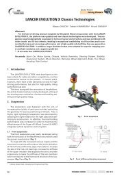
CONSTRUCTION DIAGRAM<br />
<strong>KEYLESS</strong> <strong>OPERATION</strong> <strong>SYSTEM</strong> (KOS)<br />
42B-3<br />
GENERAL INFORMATION<br />
IG knob<br />
Ignition switch<br />
Front of vehicle<br />
ASC-ECU<br />
Interior transmitter<br />
antenna assembly (Front)<br />
TPMS transmitter<br />
(Tire pressure sensor)<br />
IG knob cap<br />
Receiver<br />
antenna module<br />
Steering lock<br />
(Push switch,<br />
Steering lock unit)<br />
AC611960<br />
ECM<br />
KOS-ECU<br />
Lock switch and<br />
Unlock sensor<br />
(Passenger's side door)<br />
Exterior transmitter<br />
antenna assembly<br />
(Passenger's side)<br />
Receiver antenna assembly<br />
Interior transmitter<br />
antenna assembly (Rear)<br />
ETACS-ECU<br />
TPMS transmitter<br />
(Tire pressure sensor)<br />
TPMS transmitter<br />
(Tire pressure sensor)<br />
Lock switch and<br />
Unlock sensor<br />
(Driver's side door)<br />
Exterior transmitter<br />
antenna assembly<br />
(Driver's side)<br />
TPMS transmitter<br />
(Tire pressure sensor)<br />
Antenna and tone alarm assembly<br />
<br />
AC709237<br />
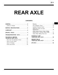
Lock switch and Unlock sensor<br />
(Driver's side door, Passenger's side door)<br />
A<br />
Section A - A<br />
Front door<br />
outside<br />
handle<br />
A<br />
Unlock sensor<br />
Lock switch<br />
AC506891<br />
Unlock<br />
sensor<br />
Door<br />
assembly<br />
AC506892<br />
Trunk lid<br />
opener switch<br />
AC709242AB<br />
TSB Revision
42B-4<br />
<strong>KEYLESS</strong> <strong>OPERATION</strong> <strong>SYSTEM</strong> (KOS)<br />
GENERAL INFORMATION<br />
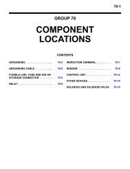
Multi information display<br />
(Built in combination meter)<br />
TPMS<br />
warning light<br />
LOW<br />
TIRE PRESSURE<br />
SERVICE<br />
REQUIRED<br />
AC709248AB<br />
Keyless operation key<br />
Indicator light<br />
Lock button<br />
Unlock button<br />
Emergency key<br />
Emergency key<br />
Trunk lid button<br />
Panic button<br />
AC613563AE<br />
.<br />
TSB Revision
Main components and functions<br />
Parts name<br />
KOS-ECU<br />
Steering lock (incorporates push switch<br />
and steering lock unit)<br />
Keyless operation key (incorporates<br />
emergency key)<br />
<strong>KEYLESS</strong> <strong>OPERATION</strong> <strong>SYSTEM</strong> (KOS)<br />
42B-5<br />
GENERAL INFORMATION<br />
Functional description<br />
Controls KOS by using the following inputs/outputs and<br />
communications.<br />
• Input from the unlock sensor and lock switch on each door,<br />
input from the push switch on the IG knob<br />
• Communications with ETACS-ECU, ECM or ASC-ECU and<br />
combination meter via CAN<br />
• Wire communication with the steering lock unit<br />
• Wireless communication with the keyless operation key via<br />
the receiver antenna module, receiver antenna assembly<br />
and interior/exterior transmitter antennas<br />
• Wireless communication with the TPMS transmitter<br />
• Output to the outer tone alarm<br />
The steering lock has two unlocking mechanisms; a mechanical<br />
mechanism that uses an emergency key and an electrical<br />
mechanism. In the electrical unlocking mechanism, the steering<br />
lock communicates with KOS-ECU via wire, and when<br />
requested by KOS-ECU, the steering lock unlocks for two<br />
seconds.<br />
• The keyless operation key receives signals sent from each<br />
interior/exterior transmitter antenna, certifies the keyless<br />
operation key ID code, calculates the key ID, and sends the<br />
reply data signal to KOS-ECU via the receiver antenna<br />
assembly. The lock button, unlock button, and trunk lid<br />
button operations of keyless operation key transmit signals<br />
to KOS-ECU via the receiver antenna assembly.<br />
• If two or more keyless operation keys registered in<br />
KOS-ECU respond at the same time, their signals would<br />
interfere. To avoid this interference, each signal from<br />
KOS-ECU is given the priority *1 data, and the keyless<br />
operation keys respond in accordance with this priority.<br />
Lock switch Driver's door Locks all the doors when a driver carrying the keyless operation<br />
Front passenger's<br />
door<br />
key presses the lock switch on the front door outside handle.<br />
Unlock sensor Driver's door The unlock sensors incorporated in the driver’s front door<br />
outside handles unlock driver’s the door when a driver carrying<br />
the keyless operation key pulls the driver’s door outside handle.<br />
Trunk lid opener switch<br />
Exterior transmitter<br />
antenna assembly<br />
Front passenger's<br />
door<br />
Driver's side<br />
Front passenger's<br />
side<br />
The unlock sensors incorporated in the passenger's front door<br />
outside handles unlock all the doors when a driver carrying the<br />
keyless operation key pulls the front door outside handle.<br />
By pressing the trunk lid opener switch on the trunk lid while<br />
he/she is carrying the keyless operation key, the trunk lid is<br />
unlocked.<br />
NOTE: With the locking of trunk lid, the locking is performed<br />
mechanically when the trunk lid is closed.<br />
Converts the data output from KOS-ECU via wire into a signal,<br />
and sends it to the keyless operation key.<br />
TSB Revision
42B-6<br />
<strong>KEYLESS</strong> <strong>OPERATION</strong> <strong>SYSTEM</strong> (KOS)<br />
GENERAL INFORMATION<br />
Parts name<br />
Interior transmitter<br />
antenna assembly<br />
Antenna & tone<br />
alarm assembly<br />
Receiver antenna module<br />
Receiver antenna assembly<br />
TPMS transmitter<br />
Front<br />
Rear<br />
Exterior transmitter<br />
antenna assembly<br />
(trunk lid)<br />
Outer tone alarm<br />
Combination meter (Multi information<br />
display, TPMS warning light)<br />
ETACS-ECU<br />
ECM<br />
ASC-ECU<br />
Functional description<br />
Converts the data output from KOS-ECU via wire into a signal,<br />
and sends it to the keyless operation key.<br />
Converts the data output from KOS-ECU via wire into a signal,<br />
and sends it to the keyless operation key.<br />
The outer tone alarm sounds when:<br />
• The doors are locked or unlocked by the door entry function.<br />
• The keyless operation key is take out of the vehicle when the<br />
IG knob is in the "LOCK" (OFF) position and the push switch<br />
is in other than the ON position.<br />
• The lock switch on the keyless operation switch is pressed<br />
when the IG knob is in the "LOCK" (OFF) position and the<br />
push switch is in other than the ON position.<br />
• The lock switch on the keyless operation key is pressed from<br />
inside the car.<br />
• The lock switch on the keyless operation key is pressed<br />
when the door is ajar.<br />
Receives the keyless operation key ID data from the keyless<br />
operation key which is needed for the engine start, and then<br />
outputs the data to KOS-ECU.<br />
Receives the operation signals from the lock/unlock buttons,<br />
trunk lid button, and panic button on the keyless operation key<br />
as well as the keyless operation key ID data which is necessary<br />
for engine start and the tire pressure signal from the TPMS<br />
transmitter. Then, sends the data to KOS-ECU.<br />
Measure tire pressure directly, then send radio frequency signal<br />
to receiver antenna assembly.<br />
Communicates with KOS-ECU via CAN. Receives the warning<br />
request or warning information from KOS-ECU, activates *2 the<br />
warning light. Warning symbol and message is additionally<br />
displayed on the multi information display<br />
Communicates with KOS-ECU via CAN. By the door<br />
lock/unlock request, trunk open request, or panic alarm request<br />
from KOS-ECU, ETACS-ECU outputs the lock/unlock signal,<br />
trunk open signal, or panic alarm signal. When the door<br />
lock/unlock signal is output, ETACS-ECU flashes or illuminates<br />
the turn signal light and dome light to notify that the lock/unlock<br />
operation is performed.<br />
Communicates with KOS-ECU via CAN. Permits/inhibits the<br />
engine starting and controls the engine operation. Send<br />
atmospheric pressure data.<br />
Communicates with KOS-ECU via CAN. Sends the vehicle<br />
speed data.<br />
NOTE: *1 : When registering the keyless operation<br />
keys, KOS-ECU numbers each key (1 to 4) in the<br />
order they are registered (initial priority). This priority<br />
is renewed each time the doors are locked/unlocked<br />
and the IG knob is pressed. For example, when only<br />
keys 1 and 3 have responded to the signal sent from<br />
KOS-ECU, the new priority of the keys would be<br />
1-3-2-4. When keys 3 and 4 have responded, then<br />
the priority of the keys becomes 3-4-1-2.<br />
NOTE: *2 : Illuminates for tire pressure warning.<br />
Flashes for about 1 minute and then continuously<br />
illuminated for TPMS malfunction warning.<br />
TSB Revision
<strong>KEYLESS</strong> <strong>OPERATION</strong> <strong>SYSTEM</strong> (KOS)<br />
42B-7<br />
GENERAL INFORMATION<br />
.<br />
System configuration<br />
Head light,<br />
Tail light<br />
Dome light,<br />
Ignition key cylinder<br />
illumination light<br />
Key reminder switch<br />
Steering lock<br />
Push switch<br />
CAN-B<br />
communication<br />
ETACS-ECU<br />
Horn<br />
Door lock actuator<br />
Trunk lid latch<br />
Steering lock unit<br />
Unlock sensor and<br />
lock switch<br />
(Driver's side door)<br />
Unlock sensor and<br />
lock switch<br />
(Passenger's side door)<br />
KOS-ECU<br />
ECM<br />
CAN-C communication<br />
ASC-ECU<br />
Turn-signal light<br />
Combination meter<br />
(Multi information display, TPMS warning light)<br />
Trunk lid opener switch<br />
Interior transmitter<br />
antenna assembly<br />
Exterior transmitter<br />
antenna assembly<br />
Outer tone alarm<br />
Radio<br />
frequency<br />
signal<br />
Receiver antenna<br />
assembly<br />
Radio<br />
frequency<br />
signal<br />
Receiver<br />
antenna<br />
module<br />
Low<br />
frequency<br />
signal<br />
Front<br />
Rear<br />
Low<br />
frequency<br />
signal<br />
Driver's side<br />
Passenger's side<br />
Trunk lid<br />
Low<br />
frequency<br />
signal<br />
Keyless operation key (Transponder is built into.)<br />
Lock/Unlock/Trunk lid button<br />
Antenna<br />
Transmission<br />
circuit<br />
CPU<br />
Battery<br />
Front tire (LH)<br />
Front tire (RH)<br />
Emergency key<br />
Panic button<br />
Pressure<br />
sensor<br />
ACC.<br />
sensor<br />
TPMS transmitter<br />
Rear tire (LH)<br />
Rear tire (RH)<br />
Indicator light<br />
AC709150AD<br />
TSB Revision
42B-8<br />
Tool<br />
a<br />
b<br />
c<br />
d<br />
e<br />
f<br />
g<br />
MB991824<br />
MB991827<br />
MB991910<br />
DO NOT USE<br />
MB991911<br />
DO NOT USE<br />
MB991914<br />
MB991825<br />
<strong>KEYLESS</strong> <strong>OPERATION</strong> <strong>SYSTEM</strong> (KOS)<br />
SPECIAL TOOLS<br />
Tool number and<br />
name<br />
MB991958<br />
a. MB991824<br />
b. MB991827<br />
c. MB991910<br />
d. MB991911<br />
e. MB991914<br />
f. MB991825<br />
g. MB991826<br />
M.U.T.-III sub<br />
assembly<br />
a. Vehicle<br />
communication<br />
interface (V.C.I.)<br />
b. M.U.T.-III USB<br />
cable<br />
c. M.U.T.-III main<br />
harness A<br />
(Vehicles with<br />
CAN<br />
communication<br />
system)<br />
d. M.U.T.-III main<br />
harness B<br />
(Vehicles without<br />
CAN<br />
communication<br />
system)<br />
e. M.U.T.-III main<br />
harness C (for<br />
Chrysler models<br />
only)<br />
f. M.U.T.-III<br />
measurement<br />
adapter<br />
g. M.U.T.-III trigger<br />
harness<br />
SPECIAL TOOLS<br />
Supersession<br />
MB991824-KIT<br />
NOTE: G: MB991826<br />
M.U.T.-III Trigger<br />
Harness is not<br />
necessary when<br />
pushing V.C.I. ENTER<br />
key.<br />
Application<br />
M1429604300123<br />
CAUTION<br />
M.U.T.-III main harness A<br />
(MB991910) should be used.<br />
M.U.T.-III main harness B and C<br />
should not be used for this<br />
vehicle.<br />
ETACS-ECU check (Diagnostic<br />
trouble code, service data)<br />
MB991826<br />
MB991958<br />
TSB Revision
<strong>KEYLESS</strong> <strong>OPERATION</strong> <strong>SYSTEM</strong> (KOS)<br />
42B-9<br />
DIAGNOSIS<br />
Tool<br />
a<br />
b<br />
c<br />
Tool number and<br />
name<br />
MB991223<br />
a. MB991219<br />
b. MB991220<br />
c. MB991221<br />
d. MB991222<br />
Harness set<br />
a. Test harness<br />
b. LED harness<br />
c. LED harness<br />
adaptor<br />
d. Probe<br />
Supersession<br />
General service tools<br />
Application<br />
Continuity check and voltage<br />
measurement at harness wire or<br />
connector for loose, corroded or<br />
damaged terminals, or terminals<br />
pushed back in the connector.<br />
a. Connector pin contact<br />
pressure inspection<br />
b. Power circuit inspection<br />
c. Power circuit inspection<br />
d. Commercial tester connection<br />
d<br />
DO NOT USE<br />
MB991223BA<br />
MB992006<br />
Extra fine probe<br />
−<br />
Making voltage and resistance<br />
measurement during<br />
troubleshooting<br />
MB992006<br />
MB990784<br />
Ornament remover<br />
General service tool<br />
Removal of steering column<br />
cover.<br />
MB990784<br />
DIAGNOSIS<br />
STANDARD FLOW OF DIAGNOSTIC<br />
TROUBLESHOOTING<br />
M1429604400078<br />
Refer to GROUP 00 −How to Use Troubleshooting/Inspection<br />
Service Points P.00-7.<br />
DIAGNOSTIC FUNCTION<br />
M1429605400297<br />
HOW TO CONNECT THE SCAN TOOL (M.U.T.-III)<br />
Required Special Tools:<br />
• MB991958: Scan Tool (M.U.T.-III Sub Assembly)<br />
• MB991824: Vehicle Communication Interface (V.C.I.)<br />
• MB991827: M.U.T.-III USB Cable<br />
• MB991910: M.U.T.-III Main Harness A<br />
TSB Revision
42B-10<br />
<strong>KEYLESS</strong> <strong>OPERATION</strong> <strong>SYSTEM</strong> (KOS)<br />
DIAGNOSIS<br />
Data link connector<br />
MB991910<br />
MB991824<br />
MB991827<br />
AC608435AB<br />
CAUTION<br />
To prevent damage to scan tool MB991958, always turn the<br />
ignition switch to the "LOCK" (OFF) position before connecting<br />
or disconnecting scan tool MB991958.<br />
1. Ensure that the ignition switch is at the "LOCK" (OFF)<br />
position.<br />
2. Start up the personal computer.<br />
3. Connect special tool MB991827 to special tool MB991824<br />
and the personal computer.<br />
4. Connect special tool MB991910 to special tool MB991824.<br />
5. Connect special tool MB991910 to the data link connector.<br />
6. Turn the power switch of special tool MB991824 to the "ON"<br />
position.<br />
NOTE: When special tool MB991824 is energized, special<br />
tool MB991824 indicator light will be illuminated in a green<br />
color.<br />
7. Start the M.U.T.-III system on the personal computer.<br />
NOTE: Disconnecting scan tool MB991958 is the reverse of the<br />
connecting sequence, making sure that the ignition switch is at<br />
the "LOCK" (OFF) position.<br />
HOW TO READ AND ERASE DIAGNOSTIC<br />
TROUBLE CODES<br />
Required Special Tools:<br />
• MB991958: Scan Tool (M.U.T.-III Sub Assembly)<br />
• MB991824: Vehicle Communication Interface (V.C.I.)<br />
• MB991827: M.U.T.-III USB Cable<br />
• MB991910: M.U.T.-III Main Harness A<br />
NOTE: If the battery voltage is low, diagnostic trouble codes will<br />
not be set. Check the battery if scan tool MB991958 does not<br />
display.<br />
1. Connect scan tool MB991958 to the data link connector.<br />
2. Turn the ignition switch to the "ON" position.<br />
3. Select "System select" from the start-up screen.<br />
4. Select "From 2006 MY" of "Model Year." When the "Vehicle<br />
Information" is displayed, check the contents.<br />
5. Select "ETACS" from "System List", and press the "OK"<br />
button.<br />
NOTE: When the "Loading Option Setup" list is displayed,<br />
check the applicable item.<br />
6. Select "Diagnostic Trouble Code." to read the DTC.<br />
7. If a DTC is set, it is shown.<br />
8. Choose "Erase DTCs" to erase the DTC.<br />
TSB Revision
<strong>KEYLESS</strong> <strong>OPERATION</strong> <strong>SYSTEM</strong> (KOS)<br />
42B-11<br />
DIAGNOSIS<br />
HOW TO DIAGNOSE THE CAN BUS LINES<br />
Required Special Tools:<br />
• MB991958: Scan Tool (M.U.T.-III Sub Assembly)<br />
• MB991824: Vehicle Communication Interface (V.C.I.)<br />
• MB991827: M.U.T.-III USB Cable<br />
• MB991910: M.U.T.-III Main Harness A<br />
1. Connect scan tool MB991958 to the data link connector.<br />
2. Turn the ignition switch to the "ON" position.<br />
3. Select "CAN bus diagnosis" from the start-up screen.<br />
4. When the vehicle information is displayed, confirm that it<br />
matches the vehicle being diagnosed.<br />
• If they match, go to step 8.<br />
• If not, go to step 5.<br />
5. Select the "view vehicle information" button.<br />
6. Enter the vehicle information and select the "OK" button.<br />
7. When the vehicle information is displayed, confirm again<br />
that it matches the vehicle being diagnosed.<br />
• If they match, go to step 8.<br />
• If not, go to step 5.<br />
8. Select the "OK" button.<br />
9. When the optional equipment screen is displayed, choose<br />
the one which the vehicle is fitted with, and then select the<br />
"OK" button.<br />
ID CODES REGISTRATION JUDGMENT TABLE<br />
CAUTION<br />
Do not replace the engine control module and<br />
KOS-ECU at the same time. When replacing several<br />
ECUs, always replace one ECU at a time, register<br />
the necessary IDs in it, and then replace the<br />
next ECU.<br />
The individual unique ID code is stored in the transponder<br />
(small transmitter) and KOS-ECU, engine<br />
control module (ECM), keyless operation key, and<br />
steering lock unit for KOS. Under the conditions<br />
shown in the table, the corresponding ID code has to<br />
be registered with KOS-ECU or the ECM again.<br />
M1429604800418<br />
NOTE: The KOS-ECU memory can memorize the<br />
maximum 4 different keyless operation keys (keyless<br />
operation key ID codes and key IDs).<br />
TSB Revision
42B-12<br />
<strong>KEYLESS</strong> <strong>OPERATION</strong> <strong>SYSTEM</strong> (KOS)<br />
DIAGNOSIS<br />
Item<br />
When the engine control module<br />
is replaced.<br />
When KOS-ECU is replaced.<br />
When the receiver antenna<br />
module is replaced.<br />
When the keyless operation key<br />
is added or replaced separately<br />
When a keyless operation key is<br />
lost.<br />
When an emergency key is<br />
added as a unit.<br />
When an emergency key is lost<br />
as a unit.<br />
When the emergency key is<br />
replaced by the full service key<br />
set or the handle lock service key<br />
set is replaced by the piece.<br />
When the key *2 is replaced by<br />
the door service key set is added<br />
by the piece.<br />
When TPMS transmitter is<br />
replaced.<br />
NOTE: .<br />
Operation contents and<br />
procedure<br />
1. Registration of ENG key code.<br />
2. VIN programmed.<br />
1. Register the steering lock unit<br />
again.<br />
2. VIN programmed.<br />
3. Register all the key IDs of<br />
keyless operation keys again.<br />
4. Register all the keyless<br />
operation key IDs of keyless<br />
operation keys again.<br />
5. Register the TPMS transmitters.<br />
Operation is not needed.<br />
1. Register all the key IDs of<br />
keyless operation keys again.<br />
2. Register all the keyless<br />
operation key IDs of keyless<br />
operation keys again.<br />
1. Register all the key IDs of<br />
keyless operation keys other<br />
than the lost one again.<br />
2. Register all the keyless<br />
operation key IDs of keyless<br />
operation keys other than the<br />
lost one again.<br />
Operation is not needed.<br />
Register the TPMS transmitters.<br />
• *1 : KOS and KOS key are indicated as F.A.S.T and F.A.S.T.-key respectively in the scan tool screen.<br />
• *2 : Key (the key that can be used to lock/unlock the door or trunk lid only)<br />
Reference page for registration<br />
contents<br />
ENG key code & VIN reg (Refer to<br />
GROUP 00 −Precautions before<br />
Service −How to Perform VIN<br />
Writing P.00-22).<br />
• Steering Lock Unit Registration,<br />
Key and F.A.S.T.-key *1<br />
Registration and TPMS<br />
transmitter ID registration (Refer<br />
to P.42B-227).<br />
• Write the VIN (Refer to GROUP<br />
00 −Precautions before Service<br />
−How to Perform VIN Writing).<br />
−<br />
Key and F.A.S.T.-key Registration<br />
(Refer to P.42B-227).<br />
−<br />
TPMS transmitter ID registration<br />
(Refer to P.42B-227).<br />
TSB Revision
<strong>KEYLESS</strong> <strong>OPERATION</strong> <strong>SYSTEM</strong> (KOS)<br />
42B-13<br />
DIAGNOSIS<br />
KEY SUPPLY UNIT<br />
KOS emergency key<br />
KOS key<br />
AC610642<br />
AC709685<br />
KEY SUPPLY UNIT LIST FOR OTHER THAN INDIVIDUAL KEY<br />
Full service key set<br />
Handle lock service key set<br />
AC610158<br />
AC610159<br />
Door service key set (LH), Door service key set<br />
(RH) <br />
NOTE: Key (It can only be used for locking and<br />
unlocking, and it cannot start the engine.)<br />
AC610062<br />
TSB Revision
42B-14<br />
Registration flow chart<br />
Start of registration.<br />
ECM is replaced.<br />
NO<br />
YES<br />
<strong>KEYLESS</strong> <strong>OPERATION</strong> <strong>SYSTEM</strong> (KOS)<br />
DIAGNOSIS<br />
1. Registration of ENG key code.<br />
2. Registration of VIN.<br />
Caution:<br />
Do not replace the ECM and the KOS-ECU simultaneously.<br />
Always replace the ECU by ones when the multiple ECU is<br />
replaced and then replace the next ECU after registering<br />
the necessary IDs.<br />
KOS-ECU<br />
is replaced.<br />
YES<br />
NO<br />
Keyless<br />
operation key is<br />
replaced or added<br />
(or lost).<br />
YES<br />
NO<br />
KOS-ECU is<br />
replaced.<br />
YES<br />
Steering lock unit<br />
is replaced.<br />
YES<br />
NO<br />
NO<br />
3. KOS ID is registered<br />
to steering lock unit.<br />
3. Automatic registration<br />
of KOS ID.<br />
4. Registration of VIN.<br />
5. Registration of<br />
key ID (every one code).<br />
6. Registration of keyless<br />
operation key ID.<br />
TPMS transmitter<br />
is replaced.<br />
YES<br />
NO<br />
End of registration.<br />
7. Registration of tire<br />
pressure sensor ID*.<br />
NOTE<br />
*: When KOS-ECU or TPMS transmitter is replaced.<br />
AC709282AB<br />
TSB Revision
<strong>KEYLESS</strong> <strong>OPERATION</strong> <strong>SYSTEM</strong> (KOS)<br />
42B-15<br />
DIAGNOSIS<br />
WARNING AND WARNING INDICATOR LIST<br />
M1429612300429<br />
If the KOS failed, operated improperly, KOS-ECU warns the driver of this by setting off the outer tone alarm<br />
and the keyless operation warning indicator, on the multi information display in the combination meter. If the<br />
TPMS fails or the tire pressure is low, KOS-ECU warns the driver of that state by the TPMS warning light and<br />
the multi information display in the combination meter.<br />
Display<br />
contents<br />
AC809614<br />
AC809615<br />
Message Item State Warning operations Warning<br />
KEY BATTERY<br />
LOW<br />
KEY NOT<br />
DETECTED<br />
Low keyless<br />
operation key<br />
battery voltage<br />
warning<br />
No keyless<br />
operation key<br />
detected inside the<br />
car<br />
The<br />
keyless<br />
operation<br />
key with<br />
low battery<br />
voltage is<br />
detected<br />
when the<br />
IG knob is<br />
pressed.<br />
No keyless<br />
operation<br />
key is<br />
detected<br />
inside the<br />
car when<br />
the IG knob<br />
is pressed.<br />
TPMS<br />
warning<br />
light<br />
−<br />
−<br />
Multi<br />
information<br />
display<br />
• Warning<br />
indicator<br />
illuminat<br />
es for 30<br />
seconds.<br />
• The<br />
outer<br />
tone<br />
alarm will<br />
not<br />
sound.<br />
• The<br />
warning<br />
indicator<br />
illuminat<br />
es for 5<br />
minutes.<br />
• The<br />
outer<br />
tone<br />
alarm will<br />
not<br />
sound.<br />
cancellation<br />
conditions<br />
(Cancels<br />
warning<br />
operations<br />
when one of<br />
the conditions<br />
met)<br />
• IG knob in<br />
"LOCK"<br />
(OFF)<br />
position<br />
and push<br />
switch<br />
OFF are<br />
detected.<br />
• 30<br />
seconds<br />
have<br />
passed<br />
after the<br />
warning<br />
output<br />
started.<br />
• IG knob in<br />
"LOCK"<br />
(OFF)<br />
position<br />
and push<br />
switch<br />
OFF are<br />
detected.<br />
• 5 minutes<br />
have<br />
passed<br />
after the<br />
warning<br />
output<br />
started.<br />
TSB Revision
42B-16<br />
Display<br />
contents<br />
AC900961<br />
−<br />
<strong>KEYLESS</strong> <strong>OPERATION</strong> <strong>SYSTEM</strong> (KOS)<br />
DIAGNOSIS<br />
Message Item State Warning operations Warning<br />
IG knob is not<br />
returned properly.<br />
Opening of<br />
the driver's<br />
door is<br />
detected<br />
when the<br />
IG knob is<br />
in ACC or<br />
LOCK<br />
position<br />
and the<br />
push switch<br />
is ON.<br />
TPMS<br />
warning<br />
light<br />
−<br />
Multi<br />
information<br />
display<br />
• The<br />
warning<br />
indicator<br />
illuminat<br />
es for 5<br />
minutes.<br />
• The<br />
outer<br />
tone<br />
alarm will<br />
not<br />
sound.<br />
• Key<br />
reminder<br />
warning<br />
tone<br />
alarm<br />
sounds<br />
until<br />
closing<br />
of the<br />
driver's<br />
door is<br />
detected.<br />
cancellation<br />
conditions<br />
(Cancels<br />
warning<br />
operations<br />
when one of<br />
the conditions<br />
met)<br />
• The IG<br />
knob in the<br />
"RUN" or<br />
"START"<br />
position, or<br />
the IG<br />
knob in the<br />
"LOCK"<br />
(OFF)<br />
position,<br />
and the<br />
push<br />
switch<br />
OFF are<br />
detected.<br />
• The<br />
driver's<br />
door is<br />
detected<br />
closed<br />
from the<br />
open<br />
position.<br />
• 5 minutes<br />
have<br />
passed<br />
after the<br />
warning<br />
output<br />
started.<br />
TSB Revision
<strong>KEYLESS</strong> <strong>OPERATION</strong> <strong>SYSTEM</strong> (KOS)<br />
42B-17<br />
DIAGNOSIS<br />
Display<br />
contents<br />
AC809615<br />
Message Item State Warning operations Warning<br />
KEY NOT<br />
DETECTED<br />
Keyless operation<br />
key take out<br />
warning<br />
The<br />
keyless<br />
operation<br />
key is taken<br />
out of the<br />
car when<br />
the IG knob<br />
is in other<br />
than the<br />
LOCK<br />
position,<br />
and all the<br />
doors are<br />
closed.<br />
TPMS<br />
warning<br />
light<br />
−<br />
Multi<br />
information<br />
display<br />
• The<br />
warning<br />
indicator<br />
illuminat<br />
es for 5<br />
minutes.<br />
• Outer<br />
tone<br />
alarm<br />
sounds<br />
for 5.69<br />
seconds<br />
in pattern<br />
2.<br />
cancellation<br />
conditions<br />
(Cancels<br />
warning<br />
operations<br />
when one of<br />
the conditions<br />
met)<br />
• IG knob in<br />
"LOCK"<br />
(OFF)<br />
position<br />
and push<br />
switch<br />
OFF are<br />
detected.<br />
• KOS-ECU<br />
has<br />
detected a<br />
keyless<br />
operation<br />
key inside<br />
the<br />
vehicle.<br />
• 5 minutes<br />
have<br />
passed<br />
after the<br />
warning<br />
output<br />
started.<br />
TSB Revision
42B-18<br />
Display<br />
contents<br />
AC900961<br />
AC809615<br />
AC809615<br />
−<br />
KEY STILL IN<br />
VEHICLE<br />
<strong>KEYLESS</strong> <strong>OPERATION</strong> <strong>SYSTEM</strong> (KOS)<br />
DIAGNOSIS<br />
Message Item State Warning operations Warning<br />
CHECK<br />
DOORS<br />
Door lock does not<br />
operate.<br />
When the<br />
front door<br />
outside<br />
handle lock<br />
switch is<br />
turned to<br />
ON position<br />
while the IG<br />
knob is in<br />
other than<br />
the LOCK<br />
position<br />
and push<br />
switch OFF.<br />
When the<br />
front door<br />
outside<br />
handle lock<br />
switch is<br />
turned to<br />
ON position<br />
while the<br />
keyless<br />
operation<br />
key is left in<br />
the<br />
vehicles.<br />
When the<br />
front door<br />
outside<br />
handle lock<br />
switch is<br />
turned to<br />
ON position<br />
while the<br />
door is ajar.<br />
TPMS<br />
warning<br />
light<br />
−<br />
Multi<br />
information<br />
display<br />
• Warning<br />
indicator<br />
illuminat<br />
es for 5<br />
seconds.<br />
• Outer<br />
tone<br />
alarm<br />
sounds<br />
for 2.96<br />
seconds<br />
in pattern<br />
1.<br />
cancellation<br />
conditions<br />
(Cancels<br />
warning<br />
operations<br />
when one of<br />
the conditions<br />
met)<br />
• IG knob in<br />
"LOCK"<br />
(OFF)<br />
position<br />
and push<br />
switch<br />
OFF are<br />
detected.<br />
• 5 seconds<br />
have<br />
passed<br />
after the<br />
warning<br />
output<br />
started.<br />
• Lock<br />
switch on<br />
the<br />
keyless<br />
operation<br />
switch is<br />
pressed<br />
again.<br />
• 5 seconds<br />
have<br />
passed<br />
after the<br />
warning<br />
output<br />
started.<br />
• All doors<br />
are closed.<br />
• 5 seconds<br />
have<br />
passed<br />
after the<br />
warning<br />
output<br />
started.<br />
TSB Revision
<strong>KEYLESS</strong> <strong>OPERATION</strong> <strong>SYSTEM</strong> (KOS)<br />
42B-19<br />
DIAGNOSIS<br />
Display<br />
contents<br />
AC809615<br />
Message Item State Warning operations Warning<br />
<strong>KEYLESS</strong><br />
<strong>OPERATION</strong><br />
<strong>SYSTEM</strong><br />
SERVICE<br />
REQUIRED<br />
System<br />
error<br />
Push<br />
switch is<br />
pressed<br />
ON from<br />
OFF when<br />
an error<br />
has been<br />
detected in<br />
EEPROM<br />
in<br />
KOS-ECU.<br />
Push<br />
switch is<br />
pressed<br />
ON from<br />
OFF while<br />
open circuit<br />
in the<br />
transmitter<br />
antennas<br />
are being<br />
detected.<br />
The push<br />
switch is<br />
pressed<br />
ON from<br />
OFF while<br />
short circuit<br />
in the<br />
power<br />
supply<br />
output<br />
(steering<br />
lock,<br />
transmitter<br />
antennas,<br />
receiver<br />
antenna<br />
module,<br />
etc.) is<br />
detected.<br />
TPMS<br />
warning<br />
light<br />
−<br />
Multi<br />
information<br />
display<br />
• The<br />
warning<br />
indicator<br />
illuminat<br />
es for 5<br />
minutes.<br />
• The<br />
outer<br />
tone<br />
alarm will<br />
not<br />
sound.<br />
cancellation<br />
conditions<br />
(Cancels<br />
warning<br />
operations<br />
when one of<br />
the conditions<br />
met)<br />
5 minutes<br />
have passed<br />
after the push<br />
switch was<br />
pressed ON<br />
and IG knob<br />
is in "LOCK"<br />
(OFF)<br />
position.<br />
TSB Revision
42B-20<br />
<strong>KEYLESS</strong> <strong>OPERATION</strong> <strong>SYSTEM</strong> (KOS)<br />
DIAGNOSIS<br />
Display<br />
contents<br />
AC809615<br />
<strong>KEYLESS</strong><br />
<strong>OPERATION</strong><br />
<strong>SYSTEM</strong><br />
SERVICE<br />
REQUIRED<br />
System<br />
error<br />
Not displayed − TPMS warning light<br />
bulb open circuit<br />
check<br />
AC809643<br />
AC809643<br />
Message Item State Warning operations Warning<br />
LOW TIRE<br />
PRESSURE<br />
TPMS<br />
SERVICE<br />
REQUIRED<br />
Tire pressure alarm<br />
TPMS<br />
failure<br />
warning<br />
ID not<br />
stored<br />
Steering<br />
lock<br />
communica<br />
tion error<br />
has been<br />
detected<br />
when the<br />
push switch<br />
was<br />
pressed<br />
ON.<br />
The IG<br />
knob is in<br />
other than<br />
the LOCK<br />
position<br />
while some<br />
error is<br />
being<br />
detected.<br />
The ignition<br />
switch is<br />
turned from<br />
"LOCK"<br />
(OFF) to<br />
"ON."<br />
The<br />
received<br />
tire<br />
pressure<br />
value is<br />
under the<br />
alarm ON<br />
threshold<br />
value.<br />
The TPMS<br />
transmitter<br />
ID is not<br />
registered<br />
in the<br />
KOS-ECU.<br />
TPMS<br />
warning<br />
light<br />
−<br />
Illuminate<br />
s for 3<br />
seconds.<br />
Illuminate<br />
s.<br />
Flashes *<br />
Multi<br />
information<br />
display<br />
• The<br />
warning<br />
indicator<br />
illuminat<br />
es for 5<br />
minutes.<br />
• The<br />
outer<br />
tone<br />
alarm will<br />
not<br />
sound.<br />
−<br />
Symbol and<br />
"LOW TIRE<br />
PRESSUR<br />
E" is<br />
displayed.<br />
Symbol and<br />
"SERVICE<br />
REQUIRED<br />
" is<br />
displayed.<br />
cancellation<br />
conditions<br />
(Cancels<br />
warning<br />
operations<br />
when one of<br />
the conditions<br />
met)<br />
5 minutes<br />
have passed<br />
after the push<br />
switch was<br />
pressed ON<br />
and IG knob<br />
is in "LOCK"<br />
(OFF)<br />
position.<br />
3 seconds<br />
have passed<br />
after the<br />
TPMS<br />
warning light<br />
is lit.<br />
The received<br />
tire pressure<br />
value is over<br />
the alarm<br />
OFF<br />
threshold<br />
value.<br />
ID is<br />
registered<br />
normally.<br />
TSB Revision
<strong>KEYLESS</strong> <strong>OPERATION</strong> <strong>SYSTEM</strong> (KOS)<br />
42B-21<br />
DIAGNOSIS<br />
Display<br />
contents<br />
AC809643<br />
Message Item State Warning operations Warning<br />
TPMS<br />
SERVICE<br />
REQUIRED<br />
TPMS<br />
failure<br />
warning<br />
Defective<br />
EEPROM<br />
Problem<br />
in signal<br />
reception<br />
Defective<br />
sensor<br />
The<br />
battery<br />
voltage of<br />
the TPMS<br />
transmitte<br />
r is low.<br />
Vehicle<br />
speed<br />
input<br />
problem<br />
Abnormal<br />
vehicle<br />
speed<br />
value<br />
Abnormality<br />
of data in<br />
the<br />
EEPROM<br />
of the<br />
KOS-ECU<br />
is detected.<br />
The signals<br />
from TPMS<br />
transmitters<br />
cannot be<br />
received<br />
while<br />
driving for<br />
about 20<br />
minutes.<br />
The sensor<br />
failure<br />
signal is<br />
received<br />
from the<br />
TPMS<br />
transmitter.<br />
The<br />
reception<br />
problem<br />
warning is<br />
activated<br />
because of<br />
the low<br />
battery<br />
voltage of<br />
the TPMS<br />
transmitter.<br />
The vehicle<br />
speed is<br />
not input.<br />
The vehicle<br />
speed<br />
value is<br />
abnormal.<br />
TPMS<br />
warning<br />
light<br />
Flashes *<br />
Multi<br />
information<br />
display<br />
Symbol and<br />
"SERVICE<br />
REQUIRED<br />
" is<br />
displayed.<br />
cancellation<br />
conditions<br />
(Cancels<br />
warning<br />
operations<br />
when one of<br />
the conditions<br />
met)<br />
Data in the<br />
EEPROM of<br />
the KOS-ECU<br />
is checked to<br />
be normal.<br />
The signal<br />
from the<br />
TPMS<br />
transmitter<br />
that was<br />
warned is<br />
received.<br />
A normal<br />
signal is<br />
received from<br />
the TPMS<br />
transmitter<br />
that was<br />
warned.<br />
The signal of<br />
normal<br />
battery<br />
voltage is<br />
received from<br />
the TPMS<br />
transmitter<br />
that was<br />
warned.<br />
The vehicle<br />
speed is<br />
input.<br />
The normal<br />
vehicle speed<br />
value is<br />
received.<br />
TSB Revision
42B-22<br />
<strong>KEYLESS</strong> <strong>OPERATION</strong> <strong>SYSTEM</strong> (KOS)<br />
DIAGNOSIS<br />
NOTE: .<br />
• * : Change to continuous illumination after flashing for about 1 minute.<br />
• When the vehicle speed exceeds 30 km/h (18.6 mph) for more than 35 seconds, the signals received from<br />
the TPMS transmitter shall be checked for 15 minutes. During that 15 minutes of reception check, when<br />
the specified value of a tire is normally received, the tire is judged as the road wheel. After the 15 minuses<br />
of measurement, if four tires are judged as the road wheels, the remaining wheel is judged as the spare<br />
tire. After the 15 minuses of measurement, if three or less tires are judged as the road wheels, the result<br />
of last measurement will be applied for the unjudged tire(s).<br />
<br />
T7<br />
T3 T3 T3 T3<br />
T1<br />
T4 T4 T4<br />
T1<br />
T2<br />
T1 : 0.08 ± 0.01 second<br />
T2 : 2.96 seconds<br />
T5 T5 T5 T5<br />
T6 T6 T6<br />
T3 : 1.01 seconds<br />
T4 : 0.55 second<br />
T5 : 0.17 ± 0.01 second<br />
T6 : 0.11 ± 0.01 second<br />
T7 : 5.69 seconds<br />
AC501053AE<br />
TSB Revision
DIAGNOSTIC TROUBLE CODE CHART<br />
<strong>KEYLESS</strong> <strong>OPERATION</strong> <strong>SYSTEM</strong> (KOS)<br />
42B-23<br />
DIAGNOSIS<br />
M1429600200492<br />
CAUTION<br />
During diagnosis, a DTC associated with other system may be set when the ignition switch is turned<br />
on with connector(s) disconnected. On completion, confirm all systems for DTC(s). If DTC(s) are set,<br />
erase them all.<br />
DTC No. Diagnostic item Reference<br />
page<br />
B1731 Engine control module communication timeout P.42B-25<br />
B1761 VIN code not programmed P.42B-28<br />
B1A08 Keyless/KOS key1 performance P.42B-29<br />
B1A09<br />
B1A0A<br />
B1A0B<br />
Keyless/KOS key2 performance<br />
Keyless/KOS key3 performance<br />
Keyless/KOS key4 performance<br />
B1A10 Keyless/KOS key 1 low battery P.42B-30<br />
B1A11<br />
B1A12<br />
B1A13<br />
Keyless/KOS key 2 low battery<br />
Keyless/KOS key 3 low battery<br />
Keyless/KOS key 4 low battery<br />
B1A24 Key ID not registered P.42B-31<br />
B1A25 Key ID unmatched P.42B-32<br />
B1A28 Engine control module authenticate error P.42B-34<br />
B1A35 Transponder read error P.42B-36<br />
B2101 IG SW start POS.circuit low P.42B-39<br />
B2102<br />
IG SW start POS.circuit high<br />
B2204 Coding data mismatch P.42B-42<br />
B2206 VIN code mismatch P.42B-44<br />
B2352 Antenna fail P.42B-46<br />
B2400 KOS key registration fail P.42B-51<br />
B2401 Keyless/KOS key ID not registered P.42B-60<br />
B2402 STL *1 unit comm.(system ID) P.42B-62<br />
B2403<br />
B2404<br />
B2405<br />
B2406<br />
B2407<br />
B2408<br />
STL *1 unit comm.(CRC)<br />
STL *1 unit comm.(function code)<br />
STL *1 unit comm.(rolling code)<br />
STL *1 unit comm.(PTC operate)<br />
STL *1 unit comm.(EEPROM)<br />
STL *1 unit comm.(solenoid)<br />
B2409 STL *1 unit comm.(No response) P.42B-67<br />
B240A DR side antenna(outdoor) open P.42B-72<br />
B240B PS side antenna(outdoor) open P.42B-75<br />
B240C Tail gate antenna(outdoor) open P.42B-78<br />
TSB Revision
42B-24<br />
<strong>KEYLESS</strong> <strong>OPERATION</strong> <strong>SYSTEM</strong> (KOS)<br />
DIAGNOSIS<br />
DTC No. Diagnostic item Reference<br />
page<br />
B240D Front antenna(indoor) open P.42B-81<br />
B240E RR antenna(indoor) open P.42B-83<br />
B2412 LF antenna power voltage P.42B-86<br />
B2413 STL *1 unit power voltage P.42B-90<br />
B2414 Unlock sensor fail P.42B-93<br />
B2415 RA *2 module power voltage P.42B-97<br />
B2416 ECU internal error P.42B-106<br />
C1608 EEPROM error P.42B-107<br />
C1900 No registration P.42B-108<br />
C1901 Vehicle speed information abnormality P.42B-110<br />
C1910 Transmitter low battery voltage abnormality 1 P.42B-112<br />
C1920 Transmitter low battery voltage abnormality 2<br />
C1930 Transmitter low battery voltage abnormality 3<br />
C1940 Transmitter low battery voltage abnormality 4<br />
C1911 Reception abnormality 1<br />
C1921 Reception abnormality 2<br />
C1931 Reception abnormality 3<br />
C1941 Reception abnormality 4<br />
C1913 Acceleration sensor abnormality 1 P.42B-118<br />
C1923 Acceleration sensor abnormality 2<br />
C1933 Acceleration sensor abnormality 3<br />
C1943 Acceleration sensor abnormality 4<br />
C1914 Pressure sensor abnormality 1<br />
C1924 Pressure sensor abnormality 2<br />
C1934 Pressure sensor abnormality 3<br />
C1944 Pressure sensor abnormality 4<br />
C1912 Tire inflation pressure warning 1 P.42B-120<br />
C1922 Tire inflation pressure warning 2<br />
C1932 Tire inflation pressure warning 3<br />
C1942 Tire inflation pressure warning 4<br />
C1915 Transmitter OFF mode 1 P.42B-123<br />
C1925 Transmitter OFF mode 2<br />
C1935 Transmitter OFF mode 3<br />
C1945 Transmitter OFF mode 4<br />
U0019 Bus off (CAN-B) P.42B-124<br />
U0141 ETACS-ECU CAN timeout P.42B-126<br />
U0151 SRS-ECU CAN timeout P.42B-128<br />
U0154 Occupant classification-ECU CAN timeout P.42B-130<br />
TSB Revision
NOTE: .<br />
• *1 : STL unit = steering lock unit<br />
• *2 : RA module = receiver antenna module<br />
DIAGNOSTIC TROUBLE CODE PROCEDURES<br />
<strong>KEYLESS</strong> <strong>OPERATION</strong> <strong>SYSTEM</strong> (KOS)<br />
42B-25<br />
DIAGNOSIS<br />
DTC No. Diagnostic item Reference<br />
page<br />
U0155 Combination meter CAN timeout P.42B-132<br />
U0164 A/C-ECU CAN timeout P.42B-134<br />
U0184 Audio CAN timeout P.42B-136<br />
U0195 Satellite radio tuner CAN timeout P.42B-138<br />
U0197 Hands free module CAN timeout P.42B-140<br />
U0245 Audio visual navigation unit CAN timeout P.42B-142<br />
U1412 Implausible vehicle speed signal received P.42B-144<br />
U1415 Coding not completed/Data fail P.42B-146<br />
U1417 Implausible coding data P.42B-147<br />
DTC B1731: Engine control module communication timeout<br />
CAUTION<br />
• When the DTC B1731 is set, be sure to diagnose<br />
the CAN bus line.<br />
• When replacing the ECU, always check that<br />
the communication circuit is normal.<br />
.<br />
DTC SET CONDITION<br />
KOS-ECU checks that the Engine Control Module<br />
data has been received via the CAN bus lines, and if<br />
not, sets the DTC No. B1731.<br />
.<br />
TECHNICAL DESCRIPTION (COMMENT)<br />
If no data [ETACS transmits engine random number<br />
data to KOS-ECU via the CAN bus lines] is received<br />
from the Engine Control Module via the CAN bus<br />
lines when the ignition switch is turned to ON position,<br />
it is judged as abnormal.<br />
.<br />
TROUBLESHOOTING HINTS<br />
• Malfunction of CAN bus line<br />
• Malfunction of KOS-ECU<br />
• Malfunction of ETACS-ECU<br />
• Malfunction of engine control module<br />
DIAGNOSIS<br />
Required Special Tools:<br />
• MB991958: Scan Tool (M.U.T.-III Sub Assembly)<br />
• MB991824: Vehicles Communication Interface (V.C.I.)<br />
• MB991827: M.U.T.-III USB Cable<br />
• MB991910: M.U.T.-III Main Harness A<br />
TSB Revision
42B-26<br />
<strong>KEYLESS</strong> <strong>OPERATION</strong> <strong>SYSTEM</strong> (KOS)<br />
DIAGNOSIS<br />
Data link connector<br />
MB991910<br />
MB991824<br />
STEP 1. Using scan tool MB991958, diagnose the CAN bus<br />
line.<br />
CAUTION<br />
To prevent damage to scan tool (MB991958), always turn<br />
the ignition switch to the "LOCK" (OFF) position before<br />
connecting or disconnecting scan tool (MB991958).<br />
(1) Connect scan tool MB991958 to the data link connector.<br />
(2) Turn the ignition switch to the "ON" position.<br />
(3) Diagnose the CAN bus line.<br />
(4) Turn the ignition switch to the "LOCK" (OFF) position.<br />
Q: Is the CAN bus line found to be normal<br />
YES : Go to Step 2.<br />
NO : Repair the CAN bus line (Refer to GROUP 54C,<br />
Diagnosis P.54C-15).<br />
MB991827<br />
AC608435AB<br />
STEP 2. Using scan tool MB991958, read the engine<br />
control module diagnostic trouble code<br />
Check again if the DTC is set to the engine control module.<br />
Q: Is the DTC set<br />
YES : Troubleshoot the MFI system (Refer to GROUP 13A,<br />
Diagnostic trouble code chart P.13A-48).<br />
NO : Go to Step 3.<br />
STEP 3. Using scan tool MB991958, read the other system<br />
diagnostic trouble code.<br />
Check if DTC U0100 is set to ETACS-ECU.<br />
Q: Is the DTC set<br />
YES : Go to Step 5.<br />
NO : Go to Step 4.<br />
TSB Revision
<strong>KEYLESS</strong> <strong>OPERATION</strong> <strong>SYSTEM</strong> (KOS)<br />
42B-27<br />
DIAGNOSIS<br />
STEP 4. Recheck for diagnostic trouble code.<br />
Check again if the DTC is set to the KOS-ECU.<br />
(1) Turn the ignition switch from "LOCK" (OFF) position to "ON"<br />
position.<br />
(2) Check if DTC is set.<br />
(3) Turn the ignition switch to the "LOCK" (OFF) position.<br />
Q: Is the DTC set<br />
YES : Replace KOS-ECU and register the ID codes. (Refer<br />
to P.42B-11.) After registering the ID codes, go to<br />
Step 6.<br />
NO : The trouble can be an intermittent malfunction (Refer<br />
to GROUP 00 −How to use<br />
Troubleshooting/inspection Service Points −How to<br />
Cope with Intermittent Malfunction P.00-15).<br />
STEP 5. Recheck for diagnostic trouble code.<br />
Check again if the DTC is set to the KOS-ECU.<br />
(1) Turn the ignition switch from "LOCK" (OFF) position to "ON"<br />
position.<br />
(2) Check if DTC is set.<br />
(3) Turn the ignition switch to the "LOCK" (OFF) position.<br />
Q: Is the DTC set<br />
YES : Replace the engine control module and record the<br />
VIN (Refer to GROUP 00 - How To Perform Vehicle<br />
Identification Number (VIN) Writing P.00-22). Then go<br />
to Step 6.<br />
NO : The procedure is complete.<br />
STEP 6. Recheck for diagnostic trouble code.<br />
Check again if the DTC is set to the WCM.<br />
(1) Turn the ignition switch from "LOCK" (OFF) position to "ON"<br />
position.<br />
(2) Check if DTC is set.<br />
(3) Turn the ignition switch to the "LOCK" (OFF) position.<br />
Q: Is the DTC set<br />
YES : Replace the ETACS-ECU.<br />
NO : The procedure is complete.<br />
TSB Revision
42B-28<br />
<strong>KEYLESS</strong> <strong>OPERATION</strong> <strong>SYSTEM</strong> (KOS)<br />
DIAGNOSIS<br />
DTC B1761: VIN code not programmed<br />
CAUTION<br />
• When the DTC No. B1761 is set, be sure to<br />
diagnose the CAN bus line.<br />
• When replacing the ECU, always check that<br />
the communication circuit is normal.<br />
.<br />
DTC SET CONDITION<br />
KOS-ECU sets DTC B1761 when no VIN is recorded<br />
in it.<br />
.<br />
TECHNICAL DESCRIPTION (COMMENT)<br />
KOS-ECU determines that the abnormality is present<br />
when no VIN is recorded in it.<br />
.<br />
TROUBLESHOOTING HINTS<br />
• VIN not programmed<br />
• Malfunction of the KOS-ECU<br />
DIAGNOSIS<br />
Required Special Tools:<br />
• MB991958: Scan Tool (M.U.T.-III Sub Assembly)<br />
• MB991824: Vehicles Communication Interface (V.C.I.)<br />
• MB991827: M.U.T.-III USB Cable<br />
• MB991910: M.U.T.-III Main Harness A<br />
Data link connector<br />
MB991910<br />
MB991824<br />
STEP 1. Using scan tool MB991958, diagnose the CAN bus<br />
line.<br />
CAUTION<br />
To prevent damage to scan tool (MB991958), always turn<br />
the ignition switch to the "LOCK" (OFF) position before<br />
connecting or disconnecting scan tool (MB991958).<br />
(1) Connect scan tool MB991958 to the data link connector.<br />
(2) Turn the ignition switch to the "ON" position.<br />
(3) Diagnose the CAN bus line.<br />
(4) Turn the ignition switch to the "LOCK" (OFF) position.<br />
Q: Is the CAN bus line found to be normal<br />
YES : Go to Step 2.<br />
NO : Repair the CAN bus line (Refer to GROUP 54C,<br />
Diagnosis P.54C-15).<br />
MB991827<br />
AC608435AB<br />
TSB Revision
<strong>KEYLESS</strong> <strong>OPERATION</strong> <strong>SYSTEM</strong> (KOS)<br />
42B-29<br />
DIAGNOSIS<br />
STEP 2. Register the VIN and recheck the diagnostic<br />
trouble code.<br />
Register VIN in KOS-ECU (Refer to GROUP 00 −How to Perform<br />
Vehicle Identification Number (VIN) Writing P.00-22) and<br />
recheck if the DTC is set.<br />
(1) Turn the ignition switch from the "LOCK" (OFF) position to<br />
the "ON" position.<br />
(2) Check if DTC is set.<br />
(3) Turn the ignition switch to the "LOCK" (OFF) position.<br />
Q: Is the DTC set<br />
YES : Replace KOS-ECU and register the ID codes (Refer<br />
to P.42B-11).<br />
NO : The procedure is complete.<br />
DTC B1A08: Keyless/KOS key1 performance<br />
DTC B1A09: Keyless/KOS key2 performance<br />
DTC B1A0A: Keyless/KOS key3 performance<br />
DTC B1A0B: Keyless/KOS key4 performance<br />
CAUTION<br />
When replacing the ECU, always check that the<br />
communication circuit is normal.<br />
.<br />
DTC SET CONDITION<br />
The mechanism which automatically changes a code<br />
for lock/unlock each time a lock operation is performed<br />
is referred to as a rolling code. If KOS-ECU<br />
receives wrong signal (out of synchronization of a<br />
rolling code) from the keyless operation key,<br />
KOS-ECU memorizes DTC B1A08.<br />
.<br />
TECHNICAL DESCRIPTION (COMMENT)<br />
• B1A08: If the difference between the rolling code<br />
for the keyless operation key 1 (the first keyless<br />
operation key registered with KOS-ECU) and that<br />
memorized by KOS-ECU is large, it is judged as<br />
abnormal.<br />
• B1A09: If the difference between the rolling code<br />
for the keyless operation key 2 (the second keyless<br />
operation key registered with KOS-ECU) and<br />
that memorized by KOS-ECU is large, it is judged<br />
as abnormal.<br />
• B1A0A: If the difference between the rolling code<br />
for the keyless operation key 3 (the third keyless<br />
operation key registered with KOS-ECU) and that<br />
memorized by KOS-ECU is large, it is judged as<br />
abnormal.<br />
• B1A0B: If the difference between the rolling code<br />
for the keyless operation key 4 (the fourth keyless<br />
operation key registered with KOS-ECU) and that<br />
memorized by KOS-ECU is large, it is judged as<br />
abnormal.<br />
.<br />
TROUBLESHOOTING HINTS<br />
• Rolling code out of synchronization<br />
• Malfunction of the keyless operation key<br />
• Malfunction of the KOS-ECU<br />
DIAGNOSIS<br />
STEP 1. Synchronize the rolling code and<br />
recheck the diagnostic trouble code.<br />
Synchronize the rolling codes, and check whether<br />
the DTC is reset.<br />
(1) Erase the DTC.<br />
(2) Turn the ignition switch from the LOCK (OFF)<br />
position to the ON position.<br />
(3) Press the lock or unlock switch of the keyless<br />
operation key for which the diagnosis code is set<br />
at least once to synchronize the rolling codes.<br />
(4) Check if the DTC is set.<br />
Q: Is the DTC set<br />
YES : Go to Step 2.<br />
NO : The diagnosis is complete.<br />
TSB Revision
42B-30<br />
<strong>KEYLESS</strong> <strong>OPERATION</strong> <strong>SYSTEM</strong> (KOS)<br />
DIAGNOSIS<br />
STEP 2. Check whether the diagnostic trouble<br />
code is reset.<br />
Replace the keyless operation key for which the DTC<br />
is set with a new one, register the key ID and keyless<br />
operation key ID (refer to P.42B-227), and check<br />
whether the DTC is reset.<br />
(1) Erase the DTC.<br />
(2) Turn the ignition switch from the LOCK (OFF)<br />
position to the ON position.<br />
(3) Check if the DTC is set.<br />
Q: Is the DTC set<br />
YES : Replace KOS-ECU and register the ID<br />
codes (Refer to P.42B-11).<br />
NO : The diagnosis is complete.<br />
DTC B1A10: Keyless/KOS key 1 low battery<br />
DTC B1A11: Keyless/KOS key 2 low battery<br />
DTC B1A12: Keyless/KOS key 3 low battery<br />
DTC B1A13: Keyless/KOS key 4 low battery<br />
CAUTION<br />
When replacing the ECU, always check that the<br />
communication circuit is normal.<br />
.<br />
DIAGNOSTIC FUNCTION<br />
If KOS-ECU receives the keyless operation key low<br />
battery voltage signal, KOS-ECU sets the DTC No.<br />
B1A10, B1A11, B1A12, or B1A13.<br />
.<br />
JUDGEMENT CRITERIA<br />
• B1A10: If KOS-ECU receives the keyless operation<br />
key 1 (the first keyless operation key registered<br />
with KOS-ECU) low battery voltage signal<br />
in five consecutive times, it is judged as abnormal.<br />
• B1A11: If KOS-ECU receives the keyless operation<br />
key 2 (the second keyless operation key registered<br />
with KOS-ECU) low battery voltage signal<br />
in five consecutive times, it is judged as abnormal.<br />
• B1A12: If KOS-ECU receives the keyless operation<br />
key 3 (the third keyless operation key registered<br />
with KOS-ECU) low battery voltage signal<br />
in five consecutive times, it is judged as abnormal.<br />
• B1A13: If KOS-ECU receives the keyless operation<br />
key 4 (the fourth keyless operation key registered<br />
with KOS-ECU) low battery voltage signal<br />
in five consecutive times, it is judged as abnormal.<br />
.<br />
PROBABLE CAUSES<br />
• Malfunction of the keyless operation key battery<br />
• Malfunction of the keyless operation key<br />
• Malfunction of KOS-ECU<br />
DIAGNOSTIC PROCEDURE<br />
STEP 1. Replace the battery in the keyless<br />
operation key and recheck the diagnostic trouble<br />
code.<br />
Replace the battery of the keyless operation key for<br />
which the DTC is set, and check whether the DTC is<br />
reset.<br />
(1) Replace the battery of the keyless operation key<br />
for which the DTC is set.<br />
(2) Erase the DTC.<br />
(3) Turn the ignition switch from the LOCK (OFF)<br />
position to the ON position.<br />
(4) Lock or unlock the keyless operation key.<br />
(5) Check if the DTC is set.<br />
Q: Is the DTC set<br />
YES : Go to Step 2.<br />
NO : The diagnosis is complete (Discharged<br />
battery).<br />
TSB Revision
STEP 2. Replace the keyless operation key and<br />
recheck the diagnostic trouble code.<br />
Replace the keyless operation key for which the DTC<br />
is set with a new one, register the key ID and keyless<br />
operation key ID (refer to P.42B-227), and check<br />
whether the DTC is reset.<br />
(1) Erase the DTC.<br />
(2) Turn the ignition switch from the LOCK (OFF)<br />
position to the ON position.<br />
(3) Check if the DTC is set.<br />
Q: Is the DTC set<br />
YES : Replace KOS-ECU and register the ID<br />
codes (Refer to P.42B-11).<br />
NO : The diagnosis is complete.<br />
<strong>KEYLESS</strong> <strong>OPERATION</strong> <strong>SYSTEM</strong> (KOS)<br />
42B-31<br />
DIAGNOSIS<br />
DTC B1A24: Key ID not registered<br />
CAUTION<br />
• When the DTC B1A24 is set, be sure to diagnose<br />
the CAN bus line.<br />
• When replacing the ECU, always check that<br />
the communication circuit is normal.<br />
.<br />
DTC SET CONDITION<br />
KOS-ECU sets DTC B1A24 when the key ID was not<br />
registered in it.<br />
.<br />
TECHNICAL DESCRIPTION (COMMENT)<br />
KOS-ECU determines that the abnormality is<br />
present, if the key ID is not registered in it when the<br />
ignition switch is turned ON.<br />
.<br />
TROUBLESHOOTING HINTS<br />
• Key ID not registered<br />
• Malfunction of the keyless operation key<br />
• Malfunction of KOS-ECU<br />
DIAGNOSIS<br />
Required Special Tools:<br />
• MB991958: Scan Tool (M.U.T.-III Sub Assembly)<br />
• MB991824: Vehicles Communication Interface (V.C.I.)<br />
• MB991827: M.U.T.-III USB Cable<br />
• MB991910: M.U.T.-III Main Harness A<br />
TSB Revision
42B-32<br />
<strong>KEYLESS</strong> <strong>OPERATION</strong> <strong>SYSTEM</strong> (KOS)<br />
DIAGNOSIS<br />
Data link connector<br />
MB991910<br />
MB991824<br />
STEP 1. Using scan tool MB991958, diagnose the CAN bus<br />
line.<br />
CAUTION<br />
To prevent damage to scan tool (MB991958), always turn<br />
the ignition switch to the "LOCK" (OFF) position before<br />
connecting or disconnecting scan tool (MB991958).<br />
(1) Connect scan tool MB991958 to the data link connector.<br />
(2) Turn the ignition switch to the "ON" position.<br />
(3) Diagnose the CAN bus line.<br />
(4) Turn the ignition switch to the "LOCK" (OFF) position.<br />
Q: Is the CAN bus line found to be normal<br />
YES : Go to Step 2.<br />
NO : Repair the CAN bus line (Refer to GROUP 54C,<br />
Diagnosis P.54C-15).<br />
MB991827<br />
AC608435AB<br />
STEP 2. Register the key ID and recheck the diagnostic<br />
trouble code.<br />
Register the key ID and keyless operation key ID of the keyless<br />
operation key by which the DTC is set (refer to P.42B-11), and<br />
recheck if the DTC is set.<br />
(1) Turn the ignition switch from the "LOCK" (OFF) position to<br />
the "ON" position.<br />
(2) Check if the DTC is set.<br />
Q: Is the DTC set<br />
YES : Replace KOS-ECU and register the ID codes (Refer<br />
to P.42B-11).<br />
NO : The procedure is complete.<br />
DTC B1A25: Key ID unmatched<br />
CAUTION<br />
• When the DTC B1A25 is set, be sure to diagnose<br />
the CAN bus line.<br />
• When replacing the ECU, always check that<br />
the communication circuit is normal.<br />
.<br />
DTC SET CONDITION<br />
KOS-ECU sets DTC B1A25 when the received key<br />
ID is different from the one registered in it.<br />
.<br />
TECHNICAL DESCRIPTION (COMMENT)<br />
KOS-ECU determines that the abnormality is<br />
present, if the key ID does not match the one registered<br />
in it when the ignition switch is turned ON.<br />
.<br />
TROUBLESHOOTING HINTS<br />
• Malfunction of the keyless operation key<br />
• Accessory key not registered<br />
• Accessory KOS-ECU not registered<br />
• Key is registered to another vehicle<br />
• Malfunction of KOS-ECU<br />
TSB Revision
<strong>KEYLESS</strong> <strong>OPERATION</strong> <strong>SYSTEM</strong> (KOS)<br />
42B-33<br />
DIAGNOSIS<br />
DIAGNOSIS<br />
Required Special Tools:<br />
• MB991958: Scan Tool (M.U.T.-III Sub Assembly)<br />
• MB991824: Vehicles Communication Interface (V.C.I.)<br />
• MB991827: M.U.T.-III USB Cable<br />
• MB991910: M.U.T.-III Main Harness A<br />
Data link connector<br />
MB991910<br />
MB991824<br />
STEP 1. Using scan tool MB991958, diagnose the CAN bus<br />
line.<br />
CAUTION<br />
To prevent damage to scan tool (MB991958), always turn<br />
the ignition switch to the "LOCK" (OFF) position before<br />
connecting or disconnecting scan tool (MB991958).<br />
(1) Connect scan tool MB991958 to the data link connector.<br />
(2) Turn the ignition switch to the "ON" position.<br />
(3) Diagnose the CAN bus line.<br />
(4) Turn the ignition switch to the "LOCK" (OFF) position.<br />
Q: Is the CAN bus line found to be normal<br />
YES : Go to Step 2.<br />
NO : Repair the CAN bus line (Refer to GROUP 54C,<br />
Diagnosis P.54C-15).<br />
MB991827<br />
AC608435AB<br />
STEP 2. Register the key ID and recheck the diagnostic<br />
trouble code.<br />
Register the key ID and keyless operation key ID of the keyless<br />
operation key by which the DTC is set (refer to P.42B-11), and<br />
recheck if the DTC is set.<br />
(1) Turn the ignition switch from the "LOCK" (OFF) position to<br />
the "ON" position.<br />
(2) Check if the DTC is set.<br />
Q: Is the DTC set<br />
YES : Go to Step 3.<br />
NO : The procedure is complete.<br />
TSB Revision
42B-34<br />
<strong>KEYLESS</strong> <strong>OPERATION</strong> <strong>SYSTEM</strong> (KOS)<br />
DIAGNOSIS<br />
STEP 3. Replace the keyless operation key and recheck<br />
the diagnostic trouble code.<br />
Replace the keyless operation key for which the DTC is set<br />
with the other key, and check whether the DTC is reset.<br />
(1) Turn the ignition switch from the "LOCK" (OFF) position to<br />
the "ON" position.<br />
(2) Check if the DTC is set.<br />
Q: Is the DTC set<br />
YES : Go to Step 4.<br />
NO : Go to Step 5.<br />
STEP 4. Register the key ID and recheck the diagnostic<br />
trouble code.<br />
Register the key ID and keyless operation key ID of the keyless<br />
operation key by which the DTC is set (refer to P.42B-11), and<br />
recheck if the DTC is set.<br />
(1) Turn the ignition switch from the "LOCK" (OFF) position to<br />
the "ON" position.<br />
(2) Check if the DTC is set.<br />
Q: Is the DTC set<br />
YES : Go to Step 5.<br />
NO : The procedure is complete.<br />
STEP 5. Replace the keyless operation key and recheck<br />
the diagnostric trouble code.<br />
Replace the keyless operation key for which the DTC is set<br />
with a new one, register the key ID and keyless operation key<br />
ID (refer to P.42B-11), and check whether the DTC is reset.<br />
(1) Turn the ignition switch from the "LOCK" (OFF) position to<br />
the "ON" position.<br />
(2) Check if the DTC is set.<br />
Q: Is the DTC set<br />
YES : Replace KOS-ECU and register the ID codes (Refer<br />
to P.42B-11).<br />
NO : The procedure is complete.<br />
DTC B1A28: Engine control module authenticate error<br />
CAUTION<br />
• When DTC B1A28 is set, be sure to diagnose<br />
the CAN bus line.<br />
• When replacing the ECU, always check that<br />
the communication circuit is normal.<br />
.<br />
DTC SET CONDITION<br />
If the key certification result by KOS-ECU does not<br />
match with the engine control module status,<br />
KOS-ECU sets DTC B1A28.<br />
.<br />
TSB Revision<br />
TECHNICAL DESCRIPTION (COMMENT)<br />
KOS-ECU determines that the abnormality is<br />
present, if the key certification result and the engine<br />
control module status do not match after the engine<br />
start permission communication is completed.<br />
.<br />
TROUBLESHOOTING HINTS<br />
• Malfunction of CAN bus line<br />
• Malfunction of KOS-ECU<br />
• Malfunction of engine control module<br />
• VIN registered in engine control module<br />
unmatched
<strong>KEYLESS</strong> <strong>OPERATION</strong> <strong>SYSTEM</strong> (KOS)<br />
42B-35<br />
DIAGNOSIS<br />
DIAGNOSIS<br />
Required Special Tools:<br />
• MB991958 Scan Tool (M.U.T.-III Sub Assembly)<br />
• MB991824: Vehicles Communication Interface (V.C.I.)<br />
• MB991827 M.U.T.-III USB Cable<br />
• MB991910 M.U.T.-III Main Harness A<br />
Data link connector<br />
MB991910<br />
MB991824<br />
STEP 1. Using scan tool MB991958, diagnose the CAN bus<br />
line.<br />
CAUTION<br />
To prevent damage to scan tool (MB991958), always turn<br />
the ignition switch to the "LOCK" (OFF) position before<br />
connecting or disconnecting scan tool (MB991958).<br />
(1) Connect scan tool MB991958 to the data link connector.<br />
(2) Turn the ignition switch to the "ON" position.<br />
(3) Diagnose the CAN bus line.<br />
(4) Turn the ignition switch to the "LOCK" (OFF) position.<br />
Q: Is the CAN bus line found to be normal<br />
YES : Go to Step 2.<br />
NO : Repair the CAN bus line (Refer to GROUP 54C,<br />
Diagnosis P.54C-15).<br />
MB991827<br />
AC608435AB<br />
STEP 2. Using scan tool MB991958, read the engine<br />
control module diagnostic trouble code.<br />
Check again if the DTC is set to the engine control module.<br />
Q: Is the DTC set<br />
YES : Troubleshoot the MFI system (Refer to GROUP 13A,<br />
Diagnostic trouble code chart P.13A-48).<br />
NO : Go to Step 3.<br />
STEP 3. Using scan tool MB991958, read the diagnostic<br />
trouble code.<br />
Check if the DTC is set to the KOS-ECU.<br />
(1) Turn the ignition switch from the "LOCK" (OFF) position to<br />
the "ON" position.<br />
(2) Check if the DTC is set.<br />
Q: Is DTC B1761 or B2206 set other than B1A28<br />
YES : Perform the troubleshooting for each DTC. Refer to<br />
P.42B-28 and P.42B-44 .<br />
NO : Go to Step 4.<br />
TSB Revision
42B-36<br />
<strong>KEYLESS</strong> <strong>OPERATION</strong> <strong>SYSTEM</strong> (KOS)<br />
DIAGNOSIS<br />
STEP 4. Recheck for diagnostic trouble code.<br />
Check again if the DTC is set to the KOS-ECU.<br />
(1) Turn the ignition switch from the "LOCK" (OFF) position to<br />
the "ON" position.<br />
(2) Check if the DTC is set.<br />
Q: Is the DTC set<br />
YES : Replace KOS-ECU and register the ID codes (Refer<br />
to P.42B-11). Then go to Step 5.<br />
NO : The diagnosis is complete.<br />
STEP 5. Recheck for diagnostic trouble code.<br />
Check again if the DTC is set to the KOS-ECU.<br />
(1) Turn the ignition switch from the "LOCK" (OFF) position to<br />
the "ON" position.<br />
(2) Check if the DTC is set.<br />
Q: Is the DTC set<br />
YES : Replace the engine control module and record VIN<br />
(Refer to GROUP 00 −How to Perform Vehicle<br />
Identification Number (VIN) Writing P.00-22).<br />
NO : The procedure is complete.<br />
DTC B1A35: Transponder read error<br />
CAUTION<br />
• When DTC B1A35 is set, be sure to diagnose<br />
the CAN bus line.<br />
• When replacing the ECU, always check that<br />
the communication circuit is normal.<br />
.<br />
DTC SET CONDITION<br />
If no transponder data can be received, KOS-ECU<br />
sets DTC B1A35.<br />
.<br />
TECHNICAL DESCRIPTION (COMMENT)<br />
KOS-ECU determines that the abnormality is<br />
present, if it cannot receive the key ID for the keyless<br />
operation key when the ignition switch is turned ON.<br />
.<br />
TROUBLESHOOTING HINTS<br />
• Insufficient inverse insertion of keyless operation<br />
key at the emergency operation<br />
• Malfunction of CAN bus line<br />
• Malfunction of the keyless operation key<br />
• Interference of the key ID<br />
• Malfunction of KOS-ECU<br />
• Ignition switch ON by the emergency key only<br />
DIAGNOSIS<br />
Required Special Tools:<br />
• MB991958: Scan Tool (M.U.T.-III Sub Assembly)<br />
• MB991824: Vehicles Communication Interface (V.C.I.)<br />
• MB991827: M.U.T.-III USB Cable<br />
• MB991910: M.U.T.-III Main Harness A<br />
TSB Revision
<strong>KEYLESS</strong> <strong>OPERATION</strong> <strong>SYSTEM</strong> (KOS)<br />
42B-37<br />
DIAGNOSIS<br />
Data link connector<br />
MB991910<br />
MB991824<br />
STEP 1. Sufficiently insert the keyless operation key in the<br />
inverted direction at the emergency operation, and<br />
recheck the diagnostic trouble code.<br />
With the emergency operation by the sufficient inverse insertion<br />
of keyless operation key, recheck if the DTC is set.<br />
CAUTION<br />
To prevent damage to scan tool (MB991958), always turn<br />
the ignition switch to the "LOCK" (OFF) position before<br />
connecting or disconnecting scan tool (MB991958).<br />
(1) Connect scan tool MB991958 to the data link connector.<br />
(2) With the emergency operation by the sufficient inverse<br />
insertion of keyless operation key, turn the ignition switch<br />
from the LOCK (OFF) position to the ON position.<br />
(3) Check if DTC is set.<br />
(4) Turn the ignition switch to the "LOCK" (OFF) position.<br />
Q: Is the DTC set<br />
YES : Go to Step 2.<br />
NO : The procedure is complete.<br />
MB991827<br />
AC608435AB<br />
STEP 2. Using scan tool MB991958, diagnose the CAN bus<br />
line.<br />
(1) Turn the ignition switch to the "ON" position.<br />
(2) Diagnose the CAN bus line.<br />
(3) Turn the ignition switch to the "LOCK" (OFF) position.<br />
Q: Is the CAN bus line found to be normal<br />
YES : Go to Step 3.<br />
NO : Repair the CAN bus line (Refer to GROUP 54C,<br />
Diagnosis P.54C-15).<br />
STEP 3. Check the emergency key and keyless operation<br />
key inserted in the key cylinder for interference.<br />
Check if there are other keys or anything that interferes with the<br />
communication (things that generate radio waves such as magnets<br />
and an air-cleaning device that has a power plug) near the<br />
key inserted in the key cylinder.<br />
Q: Are there other keys or anything that interferes with the<br />
communication<br />
YES : Move away or remove other keys or anything that<br />
interferes with the communication, and go to Step 4.<br />
NO : Go to Step 5.<br />
TSB Revision
42B-38<br />
<strong>KEYLESS</strong> <strong>OPERATION</strong> <strong>SYSTEM</strong> (KOS)<br />
DIAGNOSIS<br />
STEP 4. Recheck for diagnostic trouble code.<br />
Check again if the DTC is set to the KOS-ECU.<br />
(1) Turn the ignition switch from "LOCK" (OFF) position to "ON"<br />
position.<br />
(2) Check if DTC is set.<br />
(3) Turn the ignition switch to the "LOCK" (OFF) position.<br />
Q: Is the DTC set<br />
YES : Go to Step 5.<br />
NO : The trouble can be an intermittent malfunction (Refer<br />
to GROUP 00 −How to use<br />
Troubleshooting/inspection Service Points −How to<br />
Cope with Intermittent Malfunction P.00-15).<br />
STEP 5. Replace the keyless operation key and recheck<br />
the diagnostic trouble code.<br />
Replace the keyless operation key for which the DTC is set<br />
with the other key, and check whether the DTC is reset.<br />
(1) Turn the ignition switch from the "LOCK" (OFF) position to<br />
the "ON" position.<br />
(2) Check if the DTC is set.<br />
Q: Is the DTC set<br />
YES : Go to Step 6.<br />
NO : Go to Step 7.<br />
STEP 6. Register the key ID and recheck the diagnostic<br />
trouble code.<br />
Register the key ID and keyless operation key ID of the keyless<br />
operation key by which the DTC is set (refer to P.42B-11), and<br />
recheck if the DTC is set.<br />
(1) Turn the ignition switch from the "LOCK" (OFF) position to<br />
the "ON" position.<br />
(2) Check if the DTC is set.<br />
Q: Is the DTC set<br />
YES : Go to Step 7.<br />
NO : The procedure is complete.<br />
STEP 7. Replace the keyless operation key and recheck<br />
the diagnostic trouble code.<br />
Replace the keyless operation key for which the DTC is set<br />
with a new one, register the key ID and keyless operation key<br />
ID (refer to P.42B-11), and check whether the DTC is reset.<br />
(1) Turn the ignition switch from the "LOCK" (OFF) position to<br />
the "ON" position.<br />
(2) Check if the DTC is set.<br />
Q: Is the DTC set<br />
YES : Replace KOS-ECU and register the ID codes (Refer<br />
to P.42B-11).<br />
NO : The procedure is complete.<br />
TSB Revision
<strong>KEYLESS</strong> <strong>OPERATION</strong> <strong>SYSTEM</strong> (KOS)<br />
42B-39<br />
DIAGNOSIS<br />
DTC B2101: IG SW start POS.circuit low<br />
DTC B2102: IG SW start POS.circuit high<br />
CAUTION<br />
• If DTC B2101 or B2102 is set in KOS-ECU,<br />
always diagnose the CAN bus lines.<br />
• Before replacing the ECU, ensure that the<br />
communication circuit is normal.<br />
KOS-ECU Communication Circuit<br />
FUSIBLE<br />
LINK 34<br />
IGNITION<br />
SWITCH (IG1)<br />
ETACS-<br />
ECU<br />
IG1<br />
RELAY<br />
POWER<br />
SUPPLY<br />
KOS-ECU<br />
Connector: C-05<br />
Connector: C-317<br />
Junction block<br />
AC708950AZ<br />
AC708972AB<br />
.<br />
TSB Revision
42B-40<br />
DTC SET CONDITION<br />
If the actual ignition switch status is different from the<br />
ignition switch status information received from<br />
ETACS-ECU via CAN, KOS-ECU sets diagnostic<br />
trouble code No. B2101 or B2102.<br />
.<br />
TECHNICAL DESCRIPTION (COMMENT)<br />
If the difference in the ignition switch level shown<br />
below occurs consecutively 10 times with the ignition<br />
switch in the ON position or START position, when<br />
the CAN message (ignition switch position information)<br />
from ETACS-ECU, KOS-ECU determines that<br />
there is a problem.<br />
<strong>KEYLESS</strong> <strong>OPERATION</strong> <strong>SYSTEM</strong> (KOS)<br />
DIAGNOSIS<br />
DIAGNOSIS<br />
B2101<br />
• Status of ignition switch: OFF position<br />
• Ignition switch position information: ON<br />
B2102<br />
• Status of ignition switch: ON position<br />
• Ignition switch position information: OFF<br />
.<br />
TROUBLESHOOTING HINTS<br />
• Malfunction of CAN bus line<br />
• Malfunction of the KOS-ECU<br />
• Malfunction of the ignition switch<br />
• Damaged wiring harness and connectors<br />
• Malfunction of ETACS-ECU<br />
Required Special Tools:<br />
• MB991958: Scan Tool (M.U.T.-III Sub Assembly)<br />
• MB991824: Vehicles Communication Interface (V.C.I.)<br />
• MB991827: M.U.T.-III USB Cable<br />
• MB991910: M.U.T.-III Main Harness A<br />
Data link connector<br />
MB991910<br />
MB991824<br />
STEP 1. Using scan tool MB991958, diagnose the CAN bus<br />
line.<br />
CAUTION<br />
To prevent damage to scan tool (MB991958), always turn<br />
the ignition switch to the "LOCK" (OFF) position before<br />
connecting or disconnecting scan tool (MB991958).<br />
(1) Connect scan tool MB991958 to the data link connector.<br />
(2) Turn the ignition switch to the "ON" position.<br />
(3) Diagnose the CAN bus line.<br />
(4) Turn the ignition switch to the "LOCK" (OFF) position.<br />
Q: Is the CAN bus line found to be normal<br />
YES : Go to Step 2.<br />
NO : Repair the CAN bus line (Refer to GROUP 54C,<br />
Diagnosis P.54C-15).<br />
MB991827<br />
AC608435AB<br />
TSB Revision
<strong>KEYLESS</strong> <strong>OPERATION</strong> <strong>SYSTEM</strong> (KOS)<br />
42B-41<br />
DIAGNOSIS<br />
STEP 2. Check ETACS-ECU connector C-317 and<br />
KOS-ECU connector C-05 for loose, corroded or damaged<br />
terminals, or terminals pushed back in the connector.<br />
Q: Is ETACS-ECU connector C-317 and KOS-ECU<br />
connector C-05 in good condition<br />
YES : Go to Step 3.<br />
NO : Repair the defective connector.<br />
Harness side: C-317<br />
Harness side: C-05<br />
AC709707NL<br />
STEP 3. Check the wiring harness between KOS-ECU<br />
connector C-05 (terminal No.39) and ETACS-ECU<br />
connector C-317 (terminal No.5) for open circuit.<br />
(1) Disconnect KOS-ECU connector C-05 and ETACS-ECU<br />
connector C-317, and check the wiring harness.<br />
(2) Check the wiring harness between KOS-ECU connector<br />
C-05 (terminal No.39) and ETACS-ECU connector C-317<br />
(terminal No.5)<br />
OK: Continuity exists (2 Ω or less)<br />
Q: Is the wiring harness between KOS-ECU connector C-05<br />
(terminal No. 39) and ETACS-ECU connector C-317<br />
(terminal No. 5) in good condition<br />
YES : Go to Step 4.<br />
NO : Repair the wiring harness between KOS-ECU<br />
connector C-05 (terminal No.39) and ETACS-ECU<br />
connector C-317 (terminal No.5).<br />
STEP 4. Using scan tool MB991958, check data list.<br />
Use the ETACS-ECU data list to check the signals related to<br />
the ignition voltage.<br />
(1) Turn the ignition switch from "LOCK" (OFF) position to "ON"<br />
position.<br />
Item No. Item name Normal<br />
conditions<br />
Item 254 IG voltage Battery<br />
positive<br />
voltage<br />
Q: Does scan tool MB991958 display the item "IG voltage"<br />
as normal condition<br />
YES : Go to Step 5.<br />
NO : Diagnose the ETACS-ECU (Refer to GROUP 54A −<br />
ETACS, Diagnosis P.54A-646).<br />
TSB Revision
42B-42<br />
<strong>KEYLESS</strong> <strong>OPERATION</strong> <strong>SYSTEM</strong> (KOS)<br />
DIAGNOSIS<br />
STEP 5. Recheck for diagnostic trouble code.<br />
Check again if the DTC is set to the KOS-ECU.<br />
(1) Erase the DTC.<br />
(2) Turn the ignition switch from "LOCK" (OFF) position to "ON"<br />
position.<br />
(3) Check if DTC is set.<br />
(4) Turn the ignition switch to the "LOCK" (OFF) position.<br />
Q: Is the DTC set<br />
YES : Replace KOS-ECU and register the ID codes (Refer<br />
to P.42B-11).<br />
NO : The trouble can be an intermittent malfunction (Refer<br />
to GROUP 00 −How to use<br />
Troubleshooting/inspection Service Points −How to<br />
Cope with Intermittent Malfunction P.00-15).<br />
DTC B2204: Coding data mismatch<br />
CAUTION<br />
• When DTC B2204 is set, be sure to diagnose<br />
the CAN bus line.<br />
• When replacing the ECU, always check that<br />
the communication circuit is normal.<br />
.<br />
DTC SET CONDITION<br />
If the vehicle information data transmitted from the<br />
ETACS-ECU via the CAN bus lines is different from<br />
that registered in the KOS-ECU, the KOS-ECU sets<br />
DTC No. B2204.<br />
.<br />
TECHNICAL DESCRIPTION (COMMENT)<br />
KOS-ECU determines that the abnormality is present<br />
when the vehicle information registered in it does not<br />
match the vehicle information on the CAN bus lines.<br />
.<br />
TROUBLESHOOTING HINTS<br />
• Malfunction of CAN bus line<br />
• Malfunction of KOS-ECU<br />
• Malfunction of ETACS-ECU<br />
DIAGNOSIS<br />
Required Special Tools:<br />
• MB991958 Scan Tool (M.U.T.-III Sub Assembly)<br />
• MB991824: Vehicles Communication Interface (V.C.I.)<br />
• MB991827 M.U.T.-III USB Cable<br />
• MB991910 M.U.T.-III Main Harness A<br />
TSB Revision
<strong>KEYLESS</strong> <strong>OPERATION</strong> <strong>SYSTEM</strong> (KOS)<br />
42B-43<br />
DIAGNOSIS<br />
Data link connector<br />
MB991910<br />
MB991824<br />
STEP 1. Using scan tool MB991958, diagnose the CAN bus<br />
line.<br />
CAUTION<br />
To prevent damage to scan tool (MB991958), always turn<br />
the ignition switch to the "LOCK" (OFF) position before<br />
connecting or disconnecting scan tool (MB991958).<br />
(1) Connect scan tool MB991958 to the data link connector.<br />
(2) Turn the ignition switch to the "ON" position.<br />
(3) Diagnose the CAN bus line.<br />
(4) Turn the ignition switch to the "LOCK" (OFF) position.<br />
Q: Is the CAN bus line found to be normal<br />
YES : Go to Step 2.<br />
NO : Repair the CAN bus line (Refer to GROUP 54C,<br />
Diagnosis P.54C-15).<br />
MB991827<br />
AC608435AB<br />
STEP 2. Using scan tool MB991958, read the ETACS-ECU<br />
diagnostic trouble code<br />
Check if a coding-related DTC is set in the ETACS-ECU.<br />
Q: Is the DTC set<br />
YES : Troubleshoot the ETACS (Refer to GROUP 54A −<br />
ETACS, Diagnosis P.54A-646).<br />
NO : Go to Step 3.<br />
STEP 3. Recheck for diagnostic trouble code.<br />
Check again if the DTC is set to the WCM.<br />
(1) Erase the DTC.<br />
(2) Turn the ignition switch from "LOCK" (OFF) position to "ON"<br />
position.<br />
(3) Check if DTC is set.<br />
(4) Turn the ignition switch to the "LOCK" (OFF) position.<br />
Q: Is the DTC set<br />
YES : Replace KOS-ECU and register the ID codes (Refer<br />
to P.42B-11).<br />
NO : The trouble can be an intermittent malfunction (Refer<br />
to GROUP 00 −How to use<br />
Troubleshooting/inspection Service Points −How to<br />
Cope with Intermittent Malfunction P.00-15).<br />
TSB Revision
42B-44<br />
<strong>KEYLESS</strong> <strong>OPERATION</strong> <strong>SYSTEM</strong> (KOS)<br />
DIAGNOSIS<br />
DTC B2206: VIN code mismatch<br />
.<br />
DTC SET CONDITION<br />
KOS-ECU sets DTC B2206 when VIN registered in it<br />
and VIN that has been transmitted on the CAN bus<br />
do not match.<br />
.<br />
TECHNICAL DESCRIPTION (COMMENT)<br />
KOS-ECU determines that the abnormality is present<br />
when VIN registered in it and the one that has been<br />
transmitted on the CAN bus do not match.<br />
.<br />
TROUBLESHOOTING HINTS<br />
• Malfunction of KOS-ECU (KOS-ECU being registered<br />
to another vehicle)<br />
• Malfunction of ECM (VIN registered in ECM<br />
unmatched)<br />
DIAGNOSIS<br />
Required Special Tools:<br />
• MB991958 Scan Tool (M.U.T.-III Sub Assembly)<br />
• MB991824: Vehicles Communication Interface (V.C.I.)<br />
• MB991827 M.U.T.-III USB Cable<br />
• MB991910 M.U.T.-III Main Harness A<br />
STEP 1. Check the VIN registered in the engine control<br />
module and the VIN of the vehicle.<br />
Check if the VIN registered in the engine control module<br />
matches with the VIN of the vehicle.<br />
(1) On the system selection screen of the scan tool, select<br />
"MFI/GDI/Diesel".<br />
(2) Select "Coding."<br />
(3) Select "VIN Information."<br />
(4) Compare with the VIN of the vehicle.<br />
Q: Does the VIN of the engine control module match with<br />
the VIN of the vehicle<br />
YES : Go to Step 2.<br />
NO : Write the VIN to the engine control module. [Refer to<br />
GROUP 00 −How to Perform Vehicle Identification<br />
Number (VIN) Writing P.00-22]. Record VIN and go to<br />
Step 2.<br />
TSB Revision
<strong>KEYLESS</strong> <strong>OPERATION</strong> <strong>SYSTEM</strong> (KOS)<br />
42B-45<br />
DIAGNOSIS<br />
Data link connector<br />
MB991910<br />
MB991824<br />
STEP 2. Recheck for diagnostic trouble code.<br />
Check again if the DTC is set to the KOS-ECU.<br />
CAUTION<br />
To prevent damage to scan tool (MB991958), always turn<br />
the ignition switch to the "LOCK" (OFF) position before<br />
connecting or disconnecting scan tool (MB991958).<br />
(1) Connect scan tool MB991958 to the data link connector.<br />
(2) Turn the ignition switch to the "ON" position.<br />
(3) Check if the DTC is set.<br />
Q: Is the DTC set<br />
YES : Replace KOS-ECU and register the ID codes (Refer<br />
to P.42B-11). After registering the ID codes, go to<br />
Step 3.<br />
NO : The procedure is complete.<br />
MB991827<br />
AC608435AB<br />
STEP 3. Recheck for diagnostic trouble code.<br />
Check again if the DTC is set to the KOS-ECU.<br />
(1) Turn the ignition switch to the "ON" position.<br />
(2) Check if the DTC is set.<br />
Q: Is the DTC set<br />
YES : Replace the engine control module and record the<br />
VIN [Refer to GROUP 00 −How To Perform Vehicle<br />
Identification Number (VIN) Writing P.00-22].<br />
NO : The procedure is complete.<br />
TSB Revision
42B-46<br />
<strong>KEYLESS</strong> <strong>OPERATION</strong> <strong>SYSTEM</strong> (KOS)<br />
DIAGNOSIS<br />
DTC B2352: Antenna fail<br />
CAUTION<br />
When replacing the ECU, always check that the<br />
communication circuit is normal.<br />
Receiver Antenna Module and KOS-ECU Circuit<br />
KOS-ECU<br />
JOINT<br />
CONNECTOR (6)<br />
RECEIVER ANTENNA<br />
MODULE<br />
IMMOBILIZER<br />
ANTENNA<br />
KEY ID<br />
EMERGENCY<br />
KEY<br />
<strong>KEYLESS</strong><br />
<strong>OPERATION</strong><br />
KEY<br />
Connector: C-05<br />
Connectors: C-08, C-16<br />
C-08<br />
AC708950AZ<br />
C-16 (B)<br />
AC708951CG<br />
.<br />
DTC SET CONDITION<br />
If an open circuit or short to ground occurs in the<br />
antenna, KOS-ECU sets DTC B2352.<br />
.<br />
TECHNICAL DESCRIPTION (COMMENT)<br />
When the ignition switch is turned ON with the emergency<br />
operation by the inversely-inserted keyless<br />
operation key, KOS-ECU sends signals to the<br />
receiver antenna module. The receiver antenna<br />
transmits random numbers to the keyless operation<br />
key when it receives signals from KOS-ECU. If an<br />
open circuit or short to ground occurs on the wiring<br />
harness between KOS-ECU and receiver antenna at<br />
this time, KOS-ECU determines that there is a problem.<br />
.<br />
TROUBLESHOOTING HINTS<br />
• Malfunction of the receiver antenna module<br />
• Damaged wiring harness and connectors<br />
• Malfunction of KOS-ECU<br />
TSB Revision
<strong>KEYLESS</strong> <strong>OPERATION</strong> <strong>SYSTEM</strong> (KOS)<br />
42B-47<br />
DIAGNOSIS<br />
DIAGNOSIS<br />
Required Special Tools:<br />
• MB991958: Scan Tool (M.U.T.-III Sub Assembly)<br />
• MB991824: Vehicles Communication Interface (V.C.I.)<br />
• MB991827: M.U.T.-III USB Cable<br />
• MB991910: M.U.T.-III Main Harness A<br />
STEP 1. Check receiver antenna module connector C-08,<br />
KOS-ECU connector C-05 and joint connector (6) C-16 for<br />
loose, corroded or damaged terminals, or terminals<br />
pushed back in the connector.<br />
Q: Is the receiver antenna module connector C-08,<br />
KOS-ECU connector C-05 and joint connector (6) C-16<br />
in good condition<br />
YES : Go to Step 2.<br />
NO : Repair the defective connector.<br />
Harness side: C-08<br />
STEP 2. Check the wiring harness between the receiver<br />
antenna module connector C-08 (terminal Nos. 2, 1, 8, 12)<br />
and the KOS-ECU connector C-05 (terminal Nos. 11, 12, 32,<br />
7) for open circuit.<br />
(1) Disconnect reciever anntena module connector C-08 and<br />
KOS-ECU connector C-05, and check the wiring harness.<br />
(2) Check the wiring harness between reciever anntena<br />
module connector C-08 (terminal No.2) and KOS-ECU<br />
connector C-05 (terminal No.11)<br />
OK: Continuity exists (2 Ω or less)<br />
Harness side: C-05<br />
AC709707DZ<br />
Harness side: C-08<br />
(3) Check the wiring harness between reciever anntena<br />
module connector C-08 (terminal No.1) and KOS-ECU<br />
connector C-05 (terminal No.12)<br />
OK: Continuity exists (2 Ω or less)<br />
Harness side: C-05<br />
AC709707DZ<br />
TSB Revision
42B-48<br />
Harness side: C-08<br />
<strong>KEYLESS</strong> <strong>OPERATION</strong> <strong>SYSTEM</strong> (KOS)<br />
DIAGNOSIS<br />
(4) Check the wiring harness between reciever anntena<br />
module connector C-08 (terminal No.8) and KOS-ECU<br />
connector C-05 (terminal No.32)<br />
OK: Continuity exists (2 Ω or less)<br />
Harness side: C-05<br />
Harness side: C-08<br />
Harness side: C-05<br />
AC709707EB<br />
AC709707EC<br />
(5) Check the wiring harness between reciever anntena<br />
module connector C-08 (terminal No.12) and KOS-ECU<br />
connector C-05 (terminal No.7)<br />
OK: Continuity exists (2 Ω or less)<br />
Q: Is the wiring harness between receiver antenna module<br />
connector C-08 (terminal Nos. 2, 1, 8, 12) and the<br />
KOS-ECU connector C-05 (terminal Nos. 11, 12, 32, 7) in<br />
good condition<br />
YES : Go to Step 3.<br />
NO (receiver antenna module connector C-08 terminal<br />
No.2 −KOS-ECU connector C-05 terminal No.11.) :<br />
Repair the wiring harness between receiver antenna<br />
module connector C-08 (terminal No. 2) and the<br />
KOS-ECU connector C-05 (terminal No. 11).<br />
NO (receiver antenna module connector C-08 terminal<br />
No.1 −KOS-ECU connector C-05 terminal No.12.) :<br />
Repair the wiring harness between receiver antenna<br />
module connector C-08 (terminal No. 1) and the<br />
KOS-ECU connector C-05 (terminal No. 12).<br />
NO (receiver antenna module connector C-08 terminal<br />
No.8 −KOS-ECU connector C-05 terminal No.32.) :<br />
Repair the wiring harness between receiver antenna<br />
module connector C-08 (terminal No. 8) and the<br />
KOS-ECU connector C-05 (terminal No. 32).<br />
NO (receiver antenna module connector C-08 terminal<br />
No.12 −KOS-ECU connector C-05 terminal No.7.) :<br />
Repair the wiring harness between receiver antenna<br />
module connector C-08 (terminal No. 12) and the<br />
KOS-ECU connector C-05 (terminal No. 7).<br />
TSB Revision
<strong>KEYLESS</strong> <strong>OPERATION</strong> <strong>SYSTEM</strong> (KOS)<br />
42B-49<br />
DIAGNOSIS<br />
STEP 3. Check the wiring harness between the receiver<br />
antenna module connector C-08 (terminal Nos. 2, 1, 8, 12)<br />
and the ground for short circuit.<br />
(1) Disconnect reciever anntena module connector C-08, and<br />
check the wiring harness.<br />
(2) Check the wiring harness between reciever anntena<br />
module connector C-08 (terminal No.2) and ground<br />
OK: No Continuity<br />
Harness side: C-08<br />
AC709707FQ<br />
(3) Check the wiring harness between reciever anntena<br />
module connector C-08 (terminal No.1) and ground<br />
OK: No Continuity<br />
Harness side: C-08<br />
AC709707FR<br />
Harness side: C-08<br />
(4) Check the wiring harness between reciever anntena<br />
module connector C-08 (terminal No.8) and ground<br />
OK: No Continuity<br />
Harness side: C-08<br />
AC709707FS<br />
AC709707FT<br />
(5) Check the wiring harness between reciever anntena<br />
module connector C-08 (terminal No.12) and ground<br />
OK: No Continuity<br />
Q: Is the wiring harness between receiver antenna module<br />
connector C-08 (terminal Nos. 2, 1, 8, 12) and the ground<br />
in good condition<br />
YES : Go to Step 4.<br />
NO (receiver antenna module connector C-08 terminal<br />
No.2 −ground.) : Repair the wiring harness between<br />
receiver antenna module connector C-08 (terminal<br />
No. 2) and the ground.<br />
NO (receiver antenna module connector C-08 terminal<br />
No.1 −ground.) : Repair the wiring harness between<br />
receiver antenna module connector C-08 (terminal<br />
No. 1) and the ground.<br />
TSB Revision
42B-50<br />
<strong>KEYLESS</strong> <strong>OPERATION</strong> <strong>SYSTEM</strong> (KOS)<br />
DIAGNOSIS<br />
NO (receiver antenna module connector C-08 terminal<br />
No.8 −ground.) : Repair the wiring harness between<br />
receiver antenna module connector C-08 (terminal<br />
No. 8) and the ground.<br />
NO (receiver antenna module connector C-08 terminal<br />
No.12 −ground.) : Repair the wiring harness between<br />
receiver antenna module connector C-08 (terminal<br />
No. 12) and the ground.<br />
Data link connector<br />
MB991910<br />
MB991824<br />
STEP 4. Replace the receiver antenna module, and check<br />
whether the diagnostic trouble code is reset.<br />
CAUTION<br />
To prevent damage to scan tool MB991958, always turn the<br />
ignition switch to the "LOCK" (OFF) position before connecting<br />
or disconnecting scan tool MB991958.<br />
(1) Connect scan tool MB991958. Refer to "How to connect<br />
scan too (M.U.T.-III) P.42B-9."<br />
(2) Erase the DTC.<br />
(3) Turn the ignition switch from the "LOCK" (OFF) position to<br />
the "ON" position.<br />
(4) Check if the DTC is set.<br />
Q: Is the DTC set<br />
YES : Replace KOS-ECU and register the ID codes (Refer<br />
to P.42B-11).<br />
NO : The procedure is complete.<br />
MB991827<br />
AC608435AB<br />
TSB Revision
<strong>KEYLESS</strong> <strong>OPERATION</strong> <strong>SYSTEM</strong> (KOS)<br />
42B-51<br />
DIAGNOSIS<br />
DTC B2400: KOS key registration fail<br />
CAUTION<br />
• If DTC B2400 is set, diagnose the CAN bus<br />
lines.<br />
• When replacing the ECU, always check that<br />
the communication circuit is normal.<br />
Receiver Antenna Module and KOS-ECU Circuit<br />
KOS-ECU<br />
JOINT<br />
CONNECTOR (6)<br />
RECEIVER ANTENNA<br />
ASSEMBLY<br />
RECEIVER<br />
IMMOBILIZER<br />
ANTENNA<br />
RECEIVER ANTENNA<br />
MODULE<br />
Connectors: C-05, C-41<br />
Connectors: C-08, C-16<br />
C-16 (B)<br />
C-05<br />
C-08<br />
C-41<br />
AC708950AX<br />
AC708951CG<br />
TSB Revision
42B-52<br />
Connector: D-14<br />
<strong>KEYLESS</strong> <strong>OPERATION</strong> <strong>SYSTEM</strong> (KOS)<br />
DIAGNOSIS<br />
TECHNICAL DESCRIPTION (COMMENT)<br />
Assuming that another keyless operation key has<br />
already been registered with KOS-ECU, if the registration<br />
of the keyless operation key ID fails when a<br />
new keyless operation key is added or the existing<br />
key is replaced, KOS-ECU determines that there is a<br />
problem.<br />
.<br />
DTC SET CONDITION<br />
If the registration of the keyless operation key ID to<br />
KOS-ECU fails, KOS-ECU sets DTC B2400.<br />
.<br />
AC708955AM<br />
.<br />
TROUBLESHOOTING HINTS<br />
• Keyless operation key ID registration failure<br />
• Malfunction of the keyless operation key<br />
• Malfunction of CAN bus line<br />
• Battery drain of keyless operation key<br />
• Damaged wiring harness and connectors<br />
• Malfunction of receiver antenna assembly<br />
• Malfunction of receiver antenna module<br />
• Malfunction of KOS-ECU<br />
DIAGNOSIS<br />
Required Special Tools:<br />
• MB991958: Scan Tool (M.U.T.-III Sub Assembly)<br />
• MB991824: Vehicles Communication Interface (V.C.I.)<br />
• MB991827: M.U.T.-III USB Cable<br />
• MB991910: M.U.T.-III Main Harness A<br />
Data link connector<br />
MB991910<br />
MB991824<br />
STEP 1. Using scan tool MB991958, diagnose the CAN bus<br />
line.<br />
CAUTION<br />
To prevent damage to scan tool (MB991958), always turn<br />
the ignition switch to the "LOCK" (OFF) position before<br />
connecting or disconnecting scan tool (MB991958).<br />
(1) Connect scan tool MB991958 to the data link connector.<br />
(2) Turn the ignition switch to the "ON" position.<br />
(3) Diagnose the CAN bus line.<br />
(4) Turn the ignition switch to the "LOCK" (OFF) position.<br />
Q: Is the CAN bus line found to be normal<br />
YES : Go to Step 2.<br />
NO : Repair the CAN bus line (Refer to GROUP 54C,<br />
Diagnosis P.54C-15).<br />
MB991827<br />
AC608435AB<br />
TSB Revision
<strong>KEYLESS</strong> <strong>OPERATION</strong> <strong>SYSTEM</strong> (KOS)<br />
42B-53<br />
DIAGNOSIS<br />
STEP 2. Replace the battery in the keyless operation key<br />
and recheck the diagnostic trouble code.<br />
Replace the battery of the keyless operation key for which the<br />
DTC is set, and check whether the DTC is reset.<br />
(1) Turn the ignition switch from the "LOCK" (OFF) position to<br />
the "ON" position.<br />
(2) Check if the DTC is set.<br />
Q: Is the DTC set<br />
YES : Go to Step 3.<br />
NO : The procedure is complete (Discharged battery).<br />
STEP 3. Replace the keyless operation key and recheck<br />
the diagnostic trouble code.<br />
Replace the keyless operation key for which the DTC is set<br />
with a new one, register the key ID and keyless operation key<br />
ID (refer to P.42B-11), and check whether the DTC is reset.<br />
(1) Turn the ignition switch from the "LOCK" (OFF) position to<br />
the "ON" position.<br />
(2) Check if the DTC is set.<br />
Q: Is the DTC set<br />
YES : Go to Step 4.<br />
NO : The procedure is complete.<br />
STEP 4. Check receiver antenna module connector C-08,<br />
receiver antenna assembly connector D-14, KOS-ECU<br />
connector C-05, joint connector (6) C-16 and intermittent<br />
connector C-41 for loose, corroded or damaged terminals,<br />
or terminals pushed back in the connector.<br />
Q: Is the receiver antenna module connector C-08, receiver<br />
antenna assembly connector D-14, KOS-ECU connector<br />
C-05, joint connector (6) C-16 and intermittent<br />
connector C-41 in good condition<br />
YES : Go to Step 5.<br />
NO : Repair the defective connector.<br />
TSB Revision
42B-54<br />
<strong>KEYLESS</strong> <strong>OPERATION</strong> <strong>SYSTEM</strong> (KOS)<br />
DIAGNOSIS<br />
Harness side: D-14<br />
STEP 5. Check the wiring harness between the receiver<br />
antenna assembly connector D-14 (terminal Nos.1, 8, 12, 3,<br />
5) and the KOS-ECU connector C-05 (terminal Nos.12, 32,<br />
7, 9, 13) for open circuit.<br />
(1) Disconnect receiver antenna assembly connector D-14 and<br />
KOS-ECU connector C-05, and check the wiring harness.<br />
(2) Check the wiring harness between receiver antenna<br />
assembly connector D-14 (terminal No.1) and KOS-ECU<br />
connector C-05 (terminal No.12)<br />
OK: Continuity exists (2 Ω or less)<br />
Harness side: C-05<br />
AC709707DK<br />
Harness side: C-05<br />
(3) Check the wiring harness between receiver antenna<br />
assembly connector D-14 (terminal No.8) and KOS-ECU<br />
connector C-05 (terminal No.32)<br />
OK: Continuity exists (2 Ω or less)<br />
Harness side: D-14<br />
AC709707DL<br />
Harness side: D-14<br />
(4) Check the wiring harness between receiver antenna<br />
assembly connector D-14 (terminal No.12) and KOS-ECU<br />
connector C-05 (terminal No.7)<br />
OK: Continuity exists (2 Ω or less)<br />
Harness side: C-05<br />
AC709707DM<br />
Harness side: D-14<br />
(5) Check the wiring harness between receiver antenna<br />
assembly connector D-14 (terminal No.3) and KOS-ECU<br />
connector C-05 (terminal No.9)<br />
OK: Continuity exists (2 Ω or less)<br />
Harness side: C-05<br />
AC709707DN<br />
TSB Revision
<strong>KEYLESS</strong> <strong>OPERATION</strong> <strong>SYSTEM</strong> (KOS)<br />
42B-55<br />
DIAGNOSIS<br />
Harness side: D-14<br />
Harness side: C-05<br />
AC709707DO<br />
(6) Check the wiring harness between receiver antenna<br />
assembly connector D-14 (terminal No.5) and KOS-ECU<br />
connector C-05 (terminal No.13)<br />
OK: Continuity exists (2 Ω or less)<br />
Q: Is the wiring harness between receiver antenna<br />
assembly connector D-14 (terminal Nos.1, 8, 12, 3, 5)<br />
and the KOS-ECU connector C-05 (terminal Nos.12, 32,<br />
7, 9, 13) in good condition<br />
YES : Go to Step 6.<br />
NO (receiver antenna assembly connector D-14 terminal<br />
No.1 −KOS-ECU connector C-05 terminal No.12.) :<br />
Repair the wiring harness between receiver antenna<br />
assembly connector D-14 (terminal No.1) and the<br />
KOS-ECU connector C-05 (terminal No.12).<br />
NO (receiver antenna assembly connector D-14 terminal<br />
No.8 −KOS-ECU connector C-05 terminal No.32.) :<br />
Repair the wiring harness between receiver antenna<br />
assembly connector D-14 (terminal No.8) and the<br />
KOS-ECU connector C-05 (terminal No.32).<br />
NO (receiver antenna assembly connector D-14 terminal<br />
No.12 −KOS-ECU connector C-05 terminal No.7.) :<br />
Repair the wiring harness between receiver antenna<br />
assembly connector D-14 (terminal No.12) and the<br />
KOS-ECU connector C-05 (terminal No.7).<br />
NO (receiver antenna assembly connector D-14 terminal<br />
No.3 −KOS-ECU connector C-05 terminal No.9.) : Repair<br />
the wiring harness between receiver antenna<br />
assembly connector D-14 (terminal No.3) and the<br />
KOS-ECU connector C-05 (terminal No.9).<br />
NO (receiver antenna assembly connector D-14 terminal<br />
No.5 −KOS-ECU connector C-05 terminal No.13.) :<br />
Repair the wiring harness between receiver antenna<br />
assembly connector D-14 (terminal No.5) and the<br />
KOS-ECU connector C-05 (terminal No.13).<br />
TSB Revision
42B-56<br />
<strong>KEYLESS</strong> <strong>OPERATION</strong> <strong>SYSTEM</strong> (KOS)<br />
DIAGNOSIS<br />
STEP 6. Check the wiring harness between the receiver<br />
antenna assembly connector D-14 (terminal Nos.1, 8, 12, 3,<br />
5) and the ground for short circuit.<br />
(1) Disconnect receiver antenna assembly connector D-14,<br />
and check the wiring harness.<br />
(2) Check the wiring harness between receiver antenna<br />
assembly connector D-14 (terminal No.1) and ground<br />
OK: No continuity<br />
Harness side: D-14<br />
AC709707FZ<br />
Harness side: D-14<br />
(3) Check the wiring harness between receiver antenna<br />
assembly connector D-14 (terminal No.8) and ground<br />
OK: No continuity<br />
AC709707FY<br />
Harness side: D-14<br />
(4) Check the wiring harness between receiver antenna<br />
assembly connector D-14 (terminal No.12) and ground<br />
OK: No continuity<br />
AC709707FX<br />
(5) Check the wiring harness between receiver antenna<br />
assembly connector D-14 (terminal No.3) and ground<br />
OK: No continuity<br />
Harness side: D-14<br />
AC709707FW<br />
TSB Revision
<strong>KEYLESS</strong> <strong>OPERATION</strong> <strong>SYSTEM</strong> (KOS)<br />
42B-57<br />
DIAGNOSIS<br />
Harness side: D-14<br />
AC709707FV<br />
(6) Check the wiring harness between receiver antenna<br />
assembly connector D-14 (terminal No.5) and ground<br />
OK: No continuity<br />
Q: Is the wiring harness between receiver antenna<br />
assembly connector D-14 (terminal Nos.1, 8, 12, 3, 5)<br />
and the ground in good condition<br />
YES : Go to Step 7.<br />
NO (receiver antenna assembly connector D-14 terminal<br />
No.1 −ground.) : Repair the wiring harness between<br />
receiver antenna assembly connector D-14 (terminal<br />
No.1) and the ground.<br />
NO (receiver antenna assembly connector D-14 terminal<br />
No.8 −ground.) : Repair the wiring harness between<br />
receiver antenna assembly connector D-14 (terminal<br />
No.8) and the ground.<br />
NO (receiver antenna assembly connector D-14 terminal<br />
No.12 −ground.) : Repair the wiring harness between<br />
receiver antenna assembly connector D-14 (terminal<br />
No.12) and the ground.<br />
NO (receiver antenna assembly connector D-14 terminal<br />
No.3 −ground.) : Repair the wiring harness between<br />
receiver antenna assembly connector D-14 (terminal<br />
No.3) and the ground.<br />
NO (receiver antenna assembly connector D-14 terminal<br />
No.5 −ground.) : Repair the wiring harness between<br />
receiver antenna assembly connector D-14 (terminal<br />
No.5) and the ground.<br />
STEP 7. Replace the receiver antenna assembly, and check<br />
whether the diagnostic trouble code is reset.<br />
(1) Turn the ignition switch from the "LOCK" (OFF) position to<br />
the "ON" position.<br />
(2) Check if the DTC is set.<br />
Q: Is the DTC set<br />
YES : Go to Step 8.<br />
NO : The procedure is complete.<br />
TSB Revision
42B-58<br />
<strong>KEYLESS</strong> <strong>OPERATION</strong> <strong>SYSTEM</strong> (KOS)<br />
DIAGNOSIS<br />
Harness side: C-08<br />
STEP 8. Check the wiring harness between the receiver<br />
antenna module connector C-08 (terminal Nos. 2, 1, 8, 12)<br />
and the KOS-ECU connector C-05 (terminal Nos. 11, 12, 32,<br />
7) for open circuit.<br />
(1) Disconnect receiver antenna module connector C-08 and<br />
KOS-ECU connector C-05, and check the wiring harness.<br />
(2) Check the wiring harness between receiver antenna<br />
module connector C-08 (terminal No.2) and KOS-ECU<br />
connector C-05 (terminal No.11)<br />
OK: Continuity exists (2 Ω or less)<br />
Harness side: C-05<br />
AC709707DZ<br />
Harness side: C-08<br />
(3) Check the wiring harness between receiver antenna<br />
module connector C-08 (terminal No.1) and KOS-ECU<br />
connector C-05 (terminal No.12)<br />
OK: Continuity exists (2 Ω or less)<br />
Harness side: C-05<br />
AC709707DZ<br />
Harness side: C-08<br />
(4) Check the wiring harness between receiver antenna<br />
module connector C-08 (terminal No.8) and KOS-ECU<br />
connector C-05 (terminal No.32)<br />
OK: Continuity exists (2 Ω or less)<br />
Harness side: C-05<br />
Harness side: C-08<br />
Harness side: C-05<br />
AC709707EB<br />
AC709707EC<br />
(5) Check the wiring harness between receiver antenna<br />
module connector C-08 (terminal No.12) and KOS-ECU<br />
connector C-05 (terminal No.7)<br />
OK: Continuity exists (2 Ω or less)<br />
Q: Is the wiring harness between receiver antenna module<br />
connector C-08 (terminal Nos. 2, 1, 8, 12) and the<br />
KOS-ECU connector C-05 (terminal Nos. 11, 12, 32, 7) in<br />
good condition<br />
YES : Go to Step 9.<br />
NO (receiver antenna module connector C-08 terminal<br />
No.2 −KOS-ECU connector C-05 terminal No.11.) :<br />
Repair the wiring harness between receiver antenna<br />
module connector C-08 (terminal No. 2) and the<br />
KOS-ECU connector C-05 (terminal No. 11).<br />
TSB Revision
<strong>KEYLESS</strong> <strong>OPERATION</strong> <strong>SYSTEM</strong> (KOS)<br />
42B-59<br />
DIAGNOSIS<br />
NO (receiver antenna module connector C-08 terminal<br />
No.1 −KOS-ECU connector C-05 terminal No.12.) :<br />
Repair the wiring harness between receiver antenna<br />
module connector C-08 (terminal No. 1) and the<br />
KOS-ECU connector C-05 (terminal No. 12).<br />
NO (receiver antenna module connector C-08 terminal<br />
No.8 −KOS-ECU connector C-05 terminal No.32.) :<br />
Repair the wiring harness between receiver antenna<br />
module connector C-08 (terminal No. 8) and the<br />
KOS-ECU connector C-05 (terminal No. 32).<br />
NO (receiver antenna module connector C-08 terminal<br />
No.12 −KOS-ECU connector C-05 terminal No.7.) :<br />
Repair the wiring harness between receiver antenna<br />
module connector C-08 (terminal No. 12) and the<br />
KOS-ECU connector C-05 (terminal No. 7).<br />
STEP 9. Check the wiring harness between the receiver<br />
antenna module connector C-08 (terminal Nos.2, 1, 8, 12)<br />
and the ground for short circuit.<br />
(1) Disconnect receiver antenna module connector C-08, and<br />
check the wiring harness.<br />
(2) Check the wiring harness between receiver antenna<br />
module connector C-08 (terminal No.2) and ground<br />
OK: No continuity<br />
Harness side: C-08<br />
AC709707HK<br />
(3) Check the wiring harness between receiver antenna<br />
module connector C-08 (terminal No.1) and ground<br />
OK: No continuity<br />
Harness side: C-08<br />
AC709707GA<br />
Harness side: C-08<br />
(4) Check the wiring harness between receiver antenna<br />
module connector C-08 (terminal No.8) and ground<br />
OK: No continuity<br />
AC709707HL<br />
TSB Revision
42B-60<br />
<strong>KEYLESS</strong> <strong>OPERATION</strong> <strong>SYSTEM</strong> (KOS)<br />
DIAGNOSIS<br />
Harness side: C-08<br />
AC709707HM<br />
(5) Check the wiring harness between receiver antenna<br />
module connector C-08 (terminal No.12) and ground<br />
OK: No continuity<br />
Q: Is the wiring harness between receiver antenna module<br />
connector C-08 (terminal Nos.2, 1, 8, 12) and the ground<br />
in good condition<br />
YES : Go to Step 10.<br />
NO (receiver antenna module connector C-08 terminal<br />
No.2 −ground.) : Repair the wiring harness between<br />
receiver antenna module connector C-08 (terminal<br />
No.2) and the ground.<br />
NO (receiver antenna module connector C-08 terminal<br />
No.1 −ground.) : Repair the wiring harness between<br />
receiver antenna module connector C-08 (terminal<br />
No.1) and the ground.<br />
NO (receiver antenna module connector C-08 terminal<br />
No.8 −ground.) : Repair the wiring harness between<br />
receiver antenna module connector C-08 (terminal<br />
No.8) and the ground.<br />
NO (receiver antenna module connector C-08 terminal<br />
No.12 −ground.) : Repair the wiring harness between<br />
receiver antenna module connector C-08 (terminal<br />
No.12) and the ground.<br />
STEP 10. Replace the receiver antenna module, and check<br />
whether the diagnostic trouble code is reset.<br />
(1) Turn the ignition switch from the "LOCK" (OFF) position to<br />
the "ON" position.<br />
(2) Check if the DTC is set.<br />
Q: Is the DTC set<br />
YES : Replace KOS-ECU and register the ID codes (Refer<br />
to P.42B-11).<br />
NO : The procedure is complete.<br />
DTC B2401: Keyless/KOS key ID not registered<br />
CAUTION<br />
• If DTC B2401 is set, be sure to diagnose the<br />
CAN bus line.<br />
• When replacing the ECU, always check that<br />
the communication circuit is normal.<br />
.<br />
DIAGNOSTIC FUNCTION<br />
If no keyless operation key ID is registered with<br />
KOS-ECU or if the keyless operation key with ID not<br />
registered is used, KOS-ECU sets DTC B2401.<br />
.<br />
JUDGMENT CRITERIA<br />
If the number of the registered keyless operation<br />
keys is 0, or the registration of a keyless operation<br />
key fails when the number of the registered keyless<br />
operation keys is 0, it is judged as abnormal.<br />
.<br />
PROBABLE CAUSES<br />
• Malfunction of CAN bus line<br />
• The registration of a keyless operation key ID<br />
fails when no keyless operation key ID is registered.<br />
• Malfunction of the keyless operation key<br />
• Malfunction of KOS-ECU<br />
TSB Revision
<strong>KEYLESS</strong> <strong>OPERATION</strong> <strong>SYSTEM</strong> (KOS)<br />
42B-61<br />
DIAGNOSIS<br />
DIAGNOSIS<br />
Required Special Tools:<br />
• MB991958: Scan Tool (M.U.T.-III Sub Assembly)<br />
• MB991824: Vehicles Communication Interface (V.C.I.)<br />
• MB991827: M.U.T.-III USB Cable<br />
• MB991910: M.U.T.-III Main Harness A<br />
Data link connector<br />
MB991910<br />
MB991824<br />
STEP 1. Using scan tool MB991958, diagnose the CAN bus<br />
line.<br />
CAUTION<br />
To prevent damage to scan tool (MB991958), always turn<br />
the ignition switch to the "LOCK" (OFF) position before<br />
connecting or disconnecting scan tool (MB991958).<br />
(1) Connect scan tool MB991958 to the data link connector.<br />
(2) Turn the ignition switch to the "ON" position.<br />
(3) Diagnose the CAN bus line.<br />
(4) Turn the ignition switch to the "LOCK" (OFF) position.<br />
Q: Is the CAN bus line found to be normal<br />
YES : Go to Step 2.<br />
NO : Repair the CAN bus line (Refer to GROUP 54C,<br />
Diagnosis P.54C-15).<br />
MB991827<br />
AC608435AB<br />
STEP 2. Register the keyless operation key ID and recheck<br />
the diagnostic trouble code.<br />
Register the keyless operation key ID (refer to P.42B-11), and<br />
check whether the DTC is reset.<br />
(1) Turn the ignition switch from the "LOCK" (OFF) position to<br />
the "ON" position.<br />
(2) Check if the DTC is set.<br />
Q: Is the DTC set<br />
YES : Go to Step 3.<br />
NO : The procedure is complete.<br />
TSB Revision
42B-62<br />
<strong>KEYLESS</strong> <strong>OPERATION</strong> <strong>SYSTEM</strong> (KOS)<br />
DIAGNOSIS<br />
STEP 3. Replace the keyless operation key and recheck<br />
the diagnostic trouble code.<br />
Replace the keyless operation key for which the DTC is set<br />
with a new one, register the key ID and keyless operation key<br />
ID (refer to P.42B-11), and check whether the DTC is reset.<br />
(1) Turn the ignition switch from the "LOCK" (OFF) position to<br />
the "ON" position.<br />
(2) Check if the DTC is set.<br />
Q: Is the DTC set<br />
YES : Replace KOS-ECU and register the ID codes (Refer<br />
to P.42B-11).<br />
NO : The procedure is complete.<br />
DTC B2402: STL unit comm.(system ID)<br />
DTC B2403: STL unit comm.(CRC)<br />
DTC B2404: STL unit comm.(function code)<br />
DTC B2405: STL unit comm.(rolling code)<br />
DTC B2406: STL unit comm.(PTC operate)<br />
DTC B2407: STL unit comm.(EEPROM)<br />
DTC B2408: STL unit comm.(solenoid)<br />
CAUTION<br />
• If DTC B2402, B2403, B2404, B2405, B2406,<br />
B2407, or B2408 is set, diagnose the CAN bus<br />
lines.<br />
• Whenever the steering lock unit is replaced,<br />
ensure that the communication circuit is normal.<br />
Key Reminder Switch and KOS-ECU Circuit<br />
KEY<br />
REMINDER<br />
SWITCH<br />
KOS-ECU<br />
TSB Revision
<strong>KEYLESS</strong> <strong>OPERATION</strong> <strong>SYSTEM</strong> (KOS)<br />
42B-63<br />
DIAGNOSIS<br />
Connector: C-05<br />
Connector: C-211<br />
AC708950AZ<br />
AC708953AC<br />
.<br />
DTC SET CONDITION<br />
When the ignition push switch is pressed, the steering<br />
lock unit communicates with KOS-ECU to unlock<br />
the IG knob. However, if there is a failure shown<br />
below, the corresponding DTC is set.<br />
• B2402: System ID (vehicle specific code) failure<br />
• B2403: Cyclic Redundancy Check (CRC): The<br />
error detection strategy to detect a continuously<br />
occurring error (burst error), the calculation result<br />
discrepancy<br />
• B2404: Function code failure<br />
• B2405: Rolling code (automatically changing a<br />
code for lock/unlock each time when a lock operation<br />
is performed)<br />
• B2406: PTC thermistor continuously activated or<br />
activated to prevent solenoid abnormal heating<br />
on the communication with steering lock unit<br />
• B2407: EEPROM failure<br />
• B2408: Communication error between the steering<br />
lock unit and KOS-ECU, or solenoid failure<br />
.<br />
TECHNICAL DESCRIPTION (COMMENT)<br />
Range of check<br />
• When the IG knob unlock communication is performed<br />
by pressing the ignition push switch<br />
Judgment criteria<br />
• B2402: Steering lock unit communication error<br />
(system ID) or received system ID error<br />
• B2403: Steering lock unit communication error<br />
(CRC) or received frame CRC calculation result<br />
discrepancy<br />
• B2404: Steering lock unit communication error<br />
(function code) or received frame function code<br />
undefined<br />
• B2405: Steering lock unit communication error<br />
(rolling code) or received rolling code out of the<br />
permissible range<br />
• B2406: Steering lock unit communication error<br />
(PTC operation) or PTC thermistor activated to<br />
prevent solenoid abnormal heating<br />
• B2407: Steering lock unit communication error<br />
(EEPROM) or RRPROM failure<br />
• B2408: Steering lock unit communication error<br />
(solenoid) or solenoid failure<br />
.<br />
TROUBLESHOOTING HINTS<br />
• Malfunction of the key reminder switch (integrated<br />
into the steering lock unit)<br />
• Wiring harness or connector failure of CAN bus<br />
line<br />
• Malfunction of the KOS-ECU<br />
DIAGNOSIS<br />
Required Special Tools:<br />
• MB991958 Scan Tool (M.U.T.-III Sub Assembly)<br />
• MB991824: Vehicles Communication Interface (V.C.I.)<br />
• MB991827 M.U.T.-III USB Cable<br />
• MB991910 M.U.T.-III Main Harness A<br />
TSB Revision
42B-64<br />
<strong>KEYLESS</strong> <strong>OPERATION</strong> <strong>SYSTEM</strong> (KOS)<br />
DIAGNOSIS<br />
Data link<br />
connector<br />
MB991910<br />
MB991824<br />
ZC501967<br />
AC404789<br />
STEP 1. Using scan tool MB991958, diagnose the CAN bus<br />
line.<br />
CAUTION<br />
To prevent damage to scan tool (MB991958), always turn<br />
the ignition switch to the "LOCK" (OFF) position before<br />
connecting or disconnecting scan tool (MB991958).<br />
(1) Connect scan tool MB991958 to the data link connector.<br />
(2) Turn the ignition switch to the "ON" position.<br />
(3) Diagnose the CAN bus line.<br />
(4) Turn the ignition switch to the "LOCK" (OFF) position.<br />
Q: Is the CAN bus line found to be normal<br />
YES : Go to Step 2.<br />
NO : Repair the CAN bus line (Refer to GROUP 54C −<br />
Diagnosis P.54C-15).<br />
MB991827<br />
AC701411AB<br />
STEP 2. Diagnostic trouble code check<br />
Q: Is DTC No.B2402 set<br />
YES : Go to Step 3<br />
NO : Go to Step 6<br />
STEP 3. Check exchange of KOS-ECU<br />
Check whether the KOS-ECU was exchanged.<br />
Q: Is the check result normal<br />
YES : Go to Step 4<br />
NO : Go to Step 6<br />
STEP 4. Check exchange of steering lock unit<br />
Check whether the steering lock unit was exchanged.<br />
Q: Is the check result normal<br />
YES : Go to Step 6<br />
NO : Go to Step 5<br />
STEP 5. Check registered of steering lock unit<br />
Check whether KOS-ID was registered to the steering lock unit.<br />
Q: Is the check result normal<br />
YES : Go to Step 6<br />
NO : Check registration flow chart and register the ID<br />
codes (Refer to P.42B-11). Then go to Step 10.<br />
TSB Revision
<strong>KEYLESS</strong> <strong>OPERATION</strong> <strong>SYSTEM</strong> (KOS)<br />
42B-65<br />
DIAGNOSIS<br />
STEP 6. Check key reminder switch connector C-211 and<br />
KOS-ECU connector C-05 for loose, corroded or damaged<br />
terminals, or terminals pushed back in the connector.<br />
Q: Is the key reminder switch connector C-211 and<br />
KOS-ECU connector C-05 in good condition<br />
YES : Go to Step 7.<br />
NO : Repair the defective connector.<br />
Harness side: C-05<br />
STEP 7. Wiring harness check between C-211 key reminder<br />
switch connector and C-05 KOS-ECU connector for open<br />
circuit.<br />
(1) Disconnect C-211 key reminder switch connector and C-05<br />
KOS-ECU connector.<br />
(2) Measure at the connector side of C-211 key reminder<br />
switch connector and C-05 KOS-ECU connector.<br />
(3) Measure the resistance between the terminals.<br />
• C-211 key reminder switch connector terminal No.9 −<br />
C-05 KOS-ECU connector terminal No.5.<br />
Harness side: C-211<br />
Harness side: C-05<br />
Harness side: C-211<br />
AC709710 AB<br />
AC709710AD<br />
• C-211 key reminder switch connector terminal No.12 −<br />
C-05 KOS-ECU connector terminal No.4.<br />
OK: Continuity exists (2Ω or less)<br />
Q: Is the check result normal<br />
YES : Go to Step 8.<br />
NO (C-211 key reminder switch connector terminal No.9<br />
−C-05 KOS-ECU connector terminal No.5.) : An open<br />
circuit is present in the wiring harness between C-211<br />
key reminder switch connector terminal No. 9 and<br />
C-05 KOS-ECU connector terminal No. 5. Repair the<br />
wiring harness.<br />
NO (C-211 key reminder switch connector terminal<br />
No.12 −C-05 KOS-ECU connector terminal No.4.) : An<br />
open circuit is present in the wiring harness between<br />
C-211 key reminder switch connector terminal No. 12<br />
and C-05 KOS-ECU connector terminal No. 4. Repair<br />
the wiring harness.<br />
TSB Revision
42B-66<br />
<strong>KEYLESS</strong> <strong>OPERATION</strong> <strong>SYSTEM</strong> (KOS)<br />
DIAGNOSIS<br />
Harness side: C-211<br />
STEP 8. Check the wiring harness between the C-211 key<br />
reminder switch connector (terminal Nos. 9, 12) and the<br />
ground for short circuit.<br />
(1) Disconnect C-211 key reminder switch connector, and<br />
check the wiring harness.<br />
(2) Check the wiring harness between C-211 key reminder<br />
switch connector (terminal No.9) and ground<br />
OK: No Continuity<br />
Harness side: C-211<br />
AC709703AG<br />
AC709703AI<br />
(3) Check the wiring harness between C-211 key reminder<br />
switch connector (terminal No.12) and ground<br />
OK: No Continuity<br />
Q: Is the wiring harness between C-211 key reminder<br />
switch connector (terminal No. 9, 12) and the ground in<br />
good condition<br />
YES : Go to Step 9.<br />
NO (key reminder switch connector C-211 terminal No.9<br />
−ground.) : Repair the wiring harness between C-211 key<br />
reminder switch connector (terminal No. 9) and the<br />
ground.<br />
NO (key reminder switch connector C-211 terminal<br />
No.12 −ground.) : Repair the wiring harness C-211 key<br />
reminder switch connector (terminal No. 12) and the<br />
ground.<br />
STEP 9. Replace the key reminder switch, and check<br />
whether the diagnostic trouble code is reset.<br />
(1) Erase the DTC.<br />
(2) Turn the ignition switch from the "LOCK" (OFF) position to<br />
the "ON" position.<br />
(3) Check if the DTC is set.<br />
Q: Is the DTC set<br />
YES : Replace KOS-ECU and register the ID codes (Refer<br />
to P.42B-11).<br />
NO : The trouble can be an intermittent malfunction (Refer<br />
to GROUP 00 −How to use<br />
Troubleshooting/inspection Service Points −How to<br />
Cope with Intermittent Malfunction P.00-15).<br />
TSB Revision
<strong>KEYLESS</strong> <strong>OPERATION</strong> <strong>SYSTEM</strong> (KOS)<br />
42B-67<br />
DIAGNOSIS<br />
STEP 10. Check whether the diagnostic trouble code is<br />
reset.<br />
(1) Erase the DTC.<br />
(2) Turn the ignition switch from the "LOCK" (OFF) position to<br />
the "ON" position.<br />
(3) Check if the DTC is set.<br />
Q: Is the DTC set<br />
YES : Replace KOS-ECU and register the ID codes. (Refer<br />
to P.42B-11.)<br />
NO : The procedure is complete.<br />
DTC B2409 STL unit comm.(No response)<br />
CAUTION<br />
• If DTC B2409 is set, diagnose the CAN bus<br />
lines.<br />
• Whenever the steering lock unit is replaced,<br />
ensure that the communication circuit is normal.<br />
Key Reminder Switch and KOS-ECU Circuit<br />
KEY<br />
REMINDER<br />
SWITCH<br />
KOS-ECU<br />
TSB Revision
42B-68<br />
Connector: C-05<br />
<strong>KEYLESS</strong> <strong>OPERATION</strong> <strong>SYSTEM</strong> (KOS)<br />
DIAGNOSIS<br />
DTC SET CONDITION<br />
When the ignition push switch is pressed, the steering<br />
lock unit communicates with KOS-ECU to unlock<br />
the IG knob. If the steering lock unit communication<br />
error (no response) occurs at this time, the DTC is<br />
set.<br />
Connector: C-211<br />
AC708950AZ<br />
AC708953AC<br />
.<br />
TECHNICAL DESCRIPTION (COMMENT)<br />
When the IG knob unlock communication is performed<br />
by pressing the ignition push switch, if the<br />
steering lock unit communication error (no response)<br />
occurs, the steering lock unit is judged as abnormal.<br />
.<br />
TROUBLESHOOTING HINTS<br />
• Malfunction of the key reminder switch (integrated<br />
into the steering lock unit)<br />
• Wiring harness or connector failure of CAN bus<br />
line<br />
• Malfunction of the KOS-ECU<br />
.<br />
Data link<br />
connector<br />
MB991910<br />
MB991824<br />
ZC501967<br />
AC404789<br />
DIAGNOSIS<br />
Required Special Tools:<br />
• MB991958 Scan Tool (M.U.T.-III Sub Assembly)<br />
• MB991824: Vehicles Communication Interface (V.C.I.)<br />
• MB991827 M.U.T.-III USB Cable<br />
• MB991910 M.U.T.-III Main Harness A<br />
STEP 1. Using scan tool MB991958, diagnose the CAN bus<br />
line.<br />
CAUTION<br />
To prevent damage to scan tool (MB991958), always turn<br />
the ignition switch to the "LOCK" (OFF) position before<br />
connecting or disconnecting scan tool (MB991958).<br />
(1) Connect scan tool MB991958 to the data link connector.<br />
(2) Turn the ignition switch to the "ON" position.<br />
(3) Diagnose the CAN bus line.<br />
(4) Turn the ignition switch to the "LOCK" (OFF) position.<br />
Q: Is the CAN bus line found to be normal<br />
YES : Go to Step 2.<br />
NO : Repair the CAN bus line. (Refer to GROUP 54C −<br />
Diagnosis P.54C-15).<br />
MB991827<br />
AC701411AB<br />
TSB Revision
<strong>KEYLESS</strong> <strong>OPERATION</strong> <strong>SYSTEM</strong> (KOS)<br />
42B-69<br />
DIAGNOSIS<br />
STEP 2. Check key reminder switch connector C-211 and<br />
KOS-ECU connector C-05 for loose, corroded or damaged<br />
terminals, or terminals pushed back in the connector.<br />
Q: Is the key reminder switch connector C-211 and<br />
KOS-ECU connector C-05 in good condition<br />
YES : Go to Step 3.<br />
NO : Repair the defective connector.<br />
Harness side: C-05<br />
STEP 3. Wiring harness check between C-211 key reminder<br />
switch connector and C-05 KOS-ECU connector for open<br />
circuit.<br />
(1) Disconnect C-211 key reminder switch connector and C-05<br />
KOS-ECU connector.<br />
(2) Measure at the connector side of C-211 key reminder<br />
switch connector and C-05 KOS-ECU connector.<br />
(3) Measure the resistance between the terminals.<br />
• C-211 key reminder switch connector terminal No.9 −<br />
C-05 KOS-ECU connector terminal No.5.<br />
Harness side: C-211<br />
AC709710 AB<br />
Harness side: C-05<br />
• C-211 key reminder switch connector terminal No.11 −<br />
C-05 KOS-ECU connector terminal No.31.<br />
Harness side: C-211<br />
Harness side: C-05<br />
Harness side: C-211<br />
AC709710 AC<br />
AC709710AD<br />
• C-211 key reminder switch connector terminal No.12 −<br />
C-05 KOS-ECU connector terminal No.4.<br />
OK: Continuity exists (2Ω or less)<br />
Q: Is the check result normal<br />
YES : Go to Step 4.<br />
NO (C-211 key reminder switch connector terminal No.9<br />
−C-05 KOS-ECU connector terminal No.5.) : An open<br />
circuit is present in the wiring harness between C-211<br />
key reminder switch connector terminal No. 9 and<br />
C-05 KOS-ECU connector terminal No. 5. Repair the<br />
wiring harness.<br />
TSB Revision
42B-70<br />
<strong>KEYLESS</strong> <strong>OPERATION</strong> <strong>SYSTEM</strong> (KOS)<br />
DIAGNOSIS<br />
NO (C-211 key reminder switch connector terminal<br />
No.11 −C-05 KOS-ECU connector terminal No.31.) : An<br />
open circuit is present in the wiring harness between<br />
C-211 key reminder switch connector terminal No. 11<br />
and C-05 KOS-ECU connector terminal No. 31.<br />
Repair the wiring harness.<br />
NO (C-211 key reminder switch connector terminal<br />
No.12 −C-05 KOS-ECU connector terminal No.4.) : An<br />
open circuit is present in the wiring harness between<br />
C-211 key reminder switch connector terminal No. 12<br />
and C-05 KOS-ECU connector terminal No. 4. Repair<br />
the wiring harness.<br />
Harness side: C-211<br />
STEP 4. Check the wiring harness between the C-211 key<br />
reminder switch connector (terminal Nos. 9, 11, 12) and the<br />
ground for short circuit.<br />
(1) Disconnect C-211 key reminder switch connector, and<br />
check the wiring harness.<br />
(2) Check the wiring harness between C-211 key reminder<br />
switch connector (terminal No.9) and ground<br />
OK: No Continuity<br />
AC709703AG<br />
Harness side: C-211<br />
(3) Check the wiring harness between C-211 key reminder<br />
switch connector (terminal No.11) and ground<br />
OK: No Continuity<br />
Harness side: C-211<br />
AC709703AH<br />
AC709703AI<br />
(4) Check the wiring harness between C-211 key reminder<br />
switch connector (terminal No.12) and ground<br />
OK: No Continuity<br />
Q: Is the wiring harness between C-211 key reminder<br />
switch connector (terminal No. 9, 11, 12) and the ground<br />
in good condition<br />
YES : Go to Step 5.<br />
NO (key reminder switch connector C-211 terminal No.9<br />
−ground.) : Repair the wiring harness between C-211 key<br />
reminder switch connector (terminal No. 9) and the<br />
ground.<br />
TSB Revision
<strong>KEYLESS</strong> <strong>OPERATION</strong> <strong>SYSTEM</strong> (KOS)<br />
42B-71<br />
DIAGNOSIS<br />
NO (key reminder switch connector C-211 terminal<br />
No.11 −ground.) : Repair the wiring harness between<br />
C-211 key reminder switch connector (terminal No.<br />
11) and the ground.<br />
NO (key reminder switch connector C-211 terminal<br />
No.12 −ground.) : Repair the wiring harness C-211 key<br />
reminder switch connector (terminal No. 12) and the<br />
ground.<br />
STEP 5. Replace the key reminder switch, and check<br />
whether the diagnostic trouble code is reset.<br />
(1) Erase the DTC.<br />
(2) Turn the ignition switch from the "LOCK" (OFF) position to<br />
the "ON" position.<br />
(3) Check if the DTC is set.<br />
Q: Is the DTC set<br />
YES : Replace KOS-ECU and register the ID codes (Refer<br />
to P.42B-11).<br />
NO : The trouble can be an intermittent malfunction (Refer<br />
to GROUP 00 −How to use<br />
Troubleshooting/inspection Service Points −How to<br />
Cope with Intermittent Malfunction P.00-17).<br />
TSB Revision
42B-72<br />
<strong>KEYLESS</strong> <strong>OPERATION</strong> <strong>SYSTEM</strong> (KOS)<br />
DIAGNOSIS<br />
DTC B240A: DR side antenna(outdoor) open<br />
CAUTION<br />
When replacing the ECU, always check that the<br />
communication circuit is normal.<br />
Outside Transmission Antenna assembly (Driver's Side) Circuit<br />
<strong>KEYLESS</strong><br />
<strong>OPERATION</strong><br />
KEY<br />
OUTSIDE TRANSMISSION<br />
ANTENNA ASSEMBLY<br />
(DRIVER'S SIDE)<br />
RED-<br />
YELLOW RED-YELLOW<br />
RED-<br />
BLACK<br />
RED-<br />
BLACK<br />
RED-<br />
BLACK<br />
SKY<br />
BLUE<br />
SKY<br />
BLUE<br />
SKY<br />
BLUE<br />
KOS-ECU<br />
AC609050AC<br />
Connector: C-05<br />
Connector: C-23<br />
AC902037AB<br />
AC902038AB<br />
TSB Revision
<strong>KEYLESS</strong> <strong>OPERATION</strong> <strong>SYSTEM</strong> (KOS)<br />
42B-73<br />
DIAGNOSIS<br />
Connector: D-23<br />
AC902034AC<br />
.<br />
DTC SET CONDITION<br />
If an open circuit is detected in the outside transmission<br />
antenna (driver's side), the DTC is set.<br />
.<br />
TECHNICAL DESCRIPTION (COMMENT)<br />
When the ignition push switch is pressed, or when<br />
the antenna open circuit detection request is<br />
received from the diagnosis function, the failure is<br />
detected.<br />
.<br />
TROUBLESHOOTING HINTS<br />
• Malfunction of the outside transmission antenna<br />
assembly (driver's side)<br />
• Malfunction of the KOS-ECU<br />
• Damaged wiring harness and connectors<br />
DIAGNOSIS<br />
TSB Revision<br />
STEP 1. Check KOS-ECU connector C-05 and outside<br />
transmission antenna assembly (driver's side) connector<br />
D-23 for loose, corroded or damaged terminals, or<br />
terminals pushed back in the connector.<br />
Q: Are KOS-ECU connector C-05 and outside transmission<br />
antenna assembly (driver's side) connector D-23 in<br />
good condition<br />
YES : Go to Step 2.<br />
NO : Repair or replace the damaged component(s). Refer<br />
to GROUP 00E, Harness Connector Inspection<br />
P.00E-2. Check that the outside transmission antenna<br />
assembly (driver's side) works normally.<br />
STEP 2. Check the wiring harness between KOS-ECU<br />
connector C-05 (terminal Nos. 6, 17, 40) and outside<br />
transmission antenna assembly (driver's side) connector<br />
D-23 (terminal Nos. 3, 2, 1).<br />
• Check the communication, power supply, and ground wires<br />
for open circuit.<br />
NOTE: Also check intermediate connector C-23 for loose, corroded,<br />
or damaged terminals, or terminals pushed back in the<br />
connector. If intermediate connector C-23 is damaged, repair or<br />
replace the damaged component(s) as described in GROUP<br />
00E, Harness Connector Inspection P.00E-2.<br />
Q: Are the wiring harness between KOS-ECU connector<br />
C-05 (terminal Nos. 6, 17, 40) and outside transmission<br />
antenna assembly (driver's side) connector D-23<br />
(terminal Nos. 3, 2, 1) in good condition<br />
YES : Go to Step 3.<br />
NO : The wiring harness may be damaged or the<br />
connector(s) may have loose, corroded or damaged<br />
terminals, or terminals pushed back in the connector.<br />
Repair the wiring harness as necessary. Check that<br />
the outside transmission antenna assembly (driver's<br />
side) works normally.
42B-74<br />
<strong>KEYLESS</strong> <strong>OPERATION</strong> <strong>SYSTEM</strong> (KOS)<br />
DIAGNOSIS<br />
STEP 3. Keyless operation system communication test<br />
Check that the communication with the outside transmission<br />
antenna assembly (driver's side) is normal (Refer to Antenna<br />
Test P.42B-236).<br />
Antennas to be checked<br />
• Driver side antenna (exterior)<br />
OK: Normal is displayed.<br />
Q: Is the check result normal<br />
YES : Go to Step 4.<br />
NO : Replace the outside transmission antenna assembly<br />
(driver's side).<br />
STEP 4. Check whether the diagnostic trouble code is<br />
reset.<br />
(1) Erase the DTC.<br />
(2) Turn the ignition switch from the LOCK (OFF) position to the<br />
ON position.<br />
(3) Check if the DTC is set.<br />
Q: Is the DTC set<br />
YES : Replace KOS-ECU and register the ID codes (Refer<br />
to P.42B-11).<br />
NO : Intermittent malfunction is suspected (Refer to<br />
GROUP 00 −How to Use Troubleshooting/Inspection<br />
Service Points −How to Deal with Intermittent<br />
Malfunction P.00-15).<br />
TSB Revision
<strong>KEYLESS</strong> <strong>OPERATION</strong> <strong>SYSTEM</strong> (KOS)<br />
42B-75<br />
DIAGNOSIS<br />
DTC B240B: PS side antenna(outdoor) open<br />
CAUTION<br />
When replacing the ECU, always check that the<br />
communication circuit is normal.<br />
Outside Transmission Antenna assembly (Passenger's Side) Circuit<br />
<strong>KEYLESS</strong><br />
<strong>OPERATION</strong><br />
KEY<br />
OUTSIDE TRANSMISSION<br />
ANTENNA ASSEMBLY<br />
(PASSENGER'S SIDE)<br />
YELLOW YELLOW<br />
RED-<br />
BLACK<br />
RED-<br />
BLACK<br />
RED-<br />
BLACK<br />
SKY<br />
BLUE<br />
SKY<br />
BLUE<br />
SKY<br />
BLUE<br />
KOS-ECU<br />
AC609049AC<br />
Connectors: C-05, C-42<br />
Connector: C-23<br />
C-05<br />
C-42<br />
AC902037AC<br />
AC902038AB<br />
TSB Revision
42B-76<br />
Connector: D-42<br />
<strong>KEYLESS</strong> <strong>OPERATION</strong> <strong>SYSTEM</strong> (KOS)<br />
DIAGNOSIS<br />
.<br />
TECHNICAL DESCRIPTION (COMMENT)<br />
When the ignition push switch is pressed, or when<br />
the antenna open circuit detection request is<br />
received from the diagnosis function, the failure is<br />
detected.<br />
AC708954AP<br />
.<br />
DTC SET CONDITION<br />
If an open circuit is detected in the outside transmission<br />
antenna (passenger's side), the DTC is set.<br />
.<br />
TROUBLESHOOTING HINTS<br />
• Malfunction of the outside transmission antenna<br />
assembly (passenger's side)<br />
• Malfunction of the KOS-ECU<br />
• Damaged wiring harness and connectors<br />
DIAGNOSIS<br />
STEP 1. Check KOS-ECU connector C-05 and outside<br />
transmission antenna assembly (passenger's side)<br />
connector D-42 for loose, corroded or damaged terminals,<br />
or terminals pushed back in the connector.<br />
Q: Are KOS-ECU connector C-05 and outside transmission<br />
antenna assembly (passenger's side) connector D-42 in<br />
good condition<br />
YES : Go to Step 2.<br />
NO : Repair or replace the damaged component(s). Refer<br />
to GROUP 00E, Harness Connector Inspection<br />
P.00E-2. Check that the outside transmission antenna<br />
assembly (passenger's side) works normally.<br />
TSB Revision
<strong>KEYLESS</strong> <strong>OPERATION</strong> <strong>SYSTEM</strong> (KOS)<br />
42B-77<br />
DIAGNOSIS<br />
STEP 2. Check the wiring harness between KOS-ECU<br />
connector C-05 (terminal Nos. 6, 18, 40) and outside<br />
transmission antenna assembly (passenger's side)<br />
connector D-42 (terminal Nos. 3, 2, 1).<br />
• Check the communication, power supply, and ground wires<br />
for open circuit.<br />
NOTE: Also check intermediate connectors C-23, C-42 for<br />
loose, corroded, or damaged terminals, or terminals pushed<br />
back in the connector. If intermediate connectors C-23, C-42 is<br />
damaged, repair or replace the damaged component(s) as<br />
described in GROUP 00E, Harness Connector Inspection<br />
P.00E-2.<br />
Q: Are the wiring harness between KOS-ECU connector<br />
C-05 (terminal Nos. 6, 18, 40) and outside transmission<br />
antenna assembly (passenger's side) connector D-42<br />
(terminal Nos. 3, 2, 1) in good condition<br />
YES : Go to Step 3.<br />
NO : The wiring harness may be damaged or the<br />
connector(s) may have loose, corroded or damaged<br />
terminals, or terminals pushed back in the connector.<br />
Repair the wiring harness as necessary. Check that<br />
the outside transmission antenna assembly<br />
(passenger's side) works normally.<br />
STEP 3. Keyless operation system communication test<br />
Check that the communication with the outside transmission<br />
antenna assembly (passenger's side) is normal (Refer to<br />
Antenna Test P.42B-236).<br />
Antennas to be checked<br />
• Passenger side antenna (exterior)<br />
OK: Normal is displayed.<br />
Q: Is the check result normal<br />
YES : Go to Step 4.<br />
NO : Replace the outside transmission antenna assembly<br />
(passenger's side).<br />
STEP 4. Check whether the diagnostic trouble code is<br />
reset.<br />
(1) Erase the DTC.<br />
(2) Turn the ignition switch from the LOCK (OFF) position to the<br />
ON position.<br />
(3) Check if the DTC is set.<br />
Q: Is the DTC set<br />
YES : Replace KOS-ECU and register the ID codes (Refer<br />
to P.42B-11).<br />
NO : The procedure is complete.<br />
TSB Revision
42B-78<br />
<strong>KEYLESS</strong> <strong>OPERATION</strong> <strong>SYSTEM</strong> (KOS)<br />
DIAGNOSIS<br />
DTC B240C: Tail gate antenna(outdoor) open<br />
CAUTION<br />
When replacing the ECU, always check that the<br />
communication circuit is normal.<br />
Outside Transmission Antenna assembly (Trunk Lid) Circuit<br />
<strong>KEYLESS</strong><br />
<strong>OPERATION</strong><br />
KEY<br />
OUTSIDE TRANSMISSION<br />
ANTENNA ASSEMBLY<br />
(TRUNK LID)<br />
ORANGE<br />
SKY<br />
BLUE<br />
RED-<br />
BLACK<br />
SKY<br />
BLUE<br />
RED-<br />
BLACK<br />
ORANGE ORANGE<br />
SKY<br />
BLUE<br />
SKY<br />
BLUE<br />
RED-<br />
BLACK<br />
RED-<br />
BLACK<br />
KOS-ECU<br />
AC609423AJ<br />
Connectors: C-05, C-42<br />
Connector: C-23<br />
C-05<br />
C-42<br />
AC902037AC<br />
AC902038AB<br />
TSB Revision
<strong>KEYLESS</strong> <strong>OPERATION</strong> <strong>SYSTEM</strong> (KOS)<br />
42B-79<br />
DIAGNOSIS<br />
Connector: D-17<br />
.<br />
DTC SET CONDITION<br />
If an open circuit is detected in the outside transmission<br />
antenna (trunk lid), the DTC is set.<br />
D-17 (BR)<br />
AC902034AB<br />
.<br />
TECHNICAL DESCRIPTION (COMMENT)<br />
When the ignition push switch is pressed, or when<br />
the antenna open circuit detection request is<br />
received from the diagnosis function, the failure is<br />
detected.<br />
Connector: F-20<br />
.<br />
TROUBLESHOOTING HINTS<br />
• Malfunction of the outside transmission antenna<br />
assembly (trunk lid)<br />
• Malfunction of the KOS-ECU<br />
• Damaged wiring harness and connectors<br />
F-20 (GR)<br />
AC708970AK<br />
DIAGNOSIS<br />
STEP 1. Check KOS-ECU connector C-05 and outside<br />
transmission antenna assembly (trunk lid) connector F-20<br />
for loose, corroded or damaged terminals, or terminals<br />
pushed back in the connector.<br />
Q: Are KOS-ECU connector C-05 and outside transmission<br />
antenna assembly (trunk lid) connector F-20 in good<br />
condition<br />
YES : Go to Step 2.<br />
NO : Repair or replace the damaged component(s). Refer<br />
to GROUP 00E, Harness Connector Inspection<br />
P.00E-2. Check that the outside transmission antenna<br />
assembly (trunk lid) works normally.<br />
TSB Revision
42B-80<br />
<strong>KEYLESS</strong> <strong>OPERATION</strong> <strong>SYSTEM</strong> (KOS)<br />
DIAGNOSIS<br />
STEP 2. Check the wiring harness between KOS-ECU<br />
connector C-05 (terminal Nos. 6, 19, 40) and outside<br />
transmission antenna assembly (trunk lid) connector F-20<br />
(terminal Nos. 1, 2, 3).<br />
• Check the communication, power supply, and ground wires<br />
for open circuit.<br />
NOTE: Also check intermediate connectors C-23, C-42, D-17<br />
for loose, corroded, or damaged terminals, or terminals pushed<br />
back in the connector. If intermediate connectors C-23, C-42,<br />
D-17 is damaged, repair or replace the damaged component(s)<br />
as described in GROUP 00E, Harness Connector Inspection<br />
P.00E-2.<br />
Q: Are the wiring harness between KOS-ECU connector<br />
C-05 (terminal Nos. 6, 19, 40) and outside transmission<br />
antenna assembly (trunk lid) connector F-20 (terminal<br />
Nos. 1, 2, 3) in good condition<br />
YES : Go to Step 3.<br />
NO : The wiring harness may be damaged or the<br />
connector(s) may have loose, corroded or damaged<br />
terminals, or terminals pushed back in the connector.<br />
Repair the wiring harness as necessary. Check that<br />
the outside transmission antenna assembly (trunk lid)<br />
works normally.<br />
STEP 3. Keyless operation system communication test<br />
Check that the communication with the outside transmission<br />
antenna assembly (trunk lid) is normal (Refer to Antenna Test<br />
P.42B-236).<br />
Antennas to be checked<br />
Trunk Lid antenna (exterior)<br />
OK: Normal is displayed.<br />
Q: Is the check result normal<br />
YES : Go to Step 4.<br />
NO : Replace the outside transmission antenna assembly<br />
(trunk lid).<br />
STEP 4. Check whether the diagnostic trouble code is<br />
reset.<br />
(1) Erase the DTC.<br />
(2) Turn the ignition switch from the LOCK (OFF) position to the<br />
ON position.<br />
(3) Check if the DTC is set.<br />
Q: Is the DTC set<br />
YES : Replace KOS-ECU and register the ID codes (Refer<br />
to P.42B-11).<br />
NO : The procedure is complete.<br />
TSB Revision
<strong>KEYLESS</strong> <strong>OPERATION</strong> <strong>SYSTEM</strong> (KOS)<br />
42B-81<br />
DIAGNOSIS<br />
DTC B240D: Front antenna(indoor) open<br />
CAUTION<br />
When replacing the ECU, always check that the<br />
communication circuit is normal.<br />
Inside Transmission Antenna assembly (Front) Circuit<br />
<strong>KEYLESS</strong><br />
<strong>OPERATION</strong><br />
KEY<br />
INSIDE TRANSMISSION<br />
ANTENNA ASSEMBLY<br />
(FRONT)<br />
BLUE BLUE<br />
RED-<br />
BLACK<br />
RED-<br />
BLACK<br />
RED-<br />
BLACK<br />
SKY<br />
BLUE<br />
SKY<br />
BLUE<br />
SKY<br />
BLUE<br />
KOS-ECU<br />
Connector: C-05<br />
Connectors: C-23, C-121<br />
C-121<br />
AC902037AB<br />
C-23<br />
AC609424AC<br />
.<br />
DTC SET CONDITION<br />
If an open circuit is detected in the inside transmission<br />
antenna (front), the DTC is set.<br />
.<br />
TECHNICAL DESCRIPTION (COMMENT)<br />
When the ignition push switch is pressed, or when<br />
the antenna open circuit detection request is<br />
received from the diagnosis function, the failure is<br />
detected.<br />
.<br />
TROUBLESHOOTING HINTS<br />
• Malfunction of the inside transmission antenna<br />
assembly (front)<br />
• Malfunction of the KOS-ECU<br />
• Damaged wiring harness and connectors<br />
AC902038AC<br />
TSB Revision
42B-82<br />
<strong>KEYLESS</strong> <strong>OPERATION</strong> <strong>SYSTEM</strong> (KOS)<br />
DIAGNOSIS<br />
DIAGNOSIS<br />
STEP 1. Check KOS-ECU connector C-05 and inside<br />
transmission antenna assembly (front) connector C-121<br />
for loose, corroded or damaged terminals, or terminals<br />
pushed back in the connector.<br />
Q: Are KOS-ECU connector C-05 and inside transmission<br />
antenna assembly (front) connector C-121 in good<br />
condition<br />
YES : Go to Step 2.<br />
NO : Repair or replace the damaged component(s). Refer<br />
to GROUP 00E, Harness Connector Inspection<br />
P.00E-2. Check that the inside transmission antenna<br />
assembly (front) works normally.<br />
STEP 2. Check the wiring harness between KOS-ECU<br />
connector C-05 (terminal Nos. 6, 16, 40) and inside<br />
transmission antenna assembly (front) connector C-121<br />
(terminal Nos. 3, 2, 1).<br />
• Check the communication, power supply, and ground wires<br />
for open circuit.<br />
NOTE: Also check intermediate connector C-23 for loose, corroded,<br />
or damaged terminals, or terminals pushed back in the<br />
connector. If intermediate connector C-23 is damaged, repair or<br />
replace the damaged component(s) as described in GROUP<br />
00E, Harness Connector Inspection P.00E-2.<br />
Q: Are the wiring harness between KOS-ECU connector<br />
C-05 (terminal Nos. 6, 16, 40) and inside transmission<br />
antenna assembly (front) connector C-121 (terminal<br />
Nos. 3, 2, 1) in good condition<br />
YES : Go to Step 3.<br />
NO : The wiring harness may be damaged or the<br />
connector(s) may have loose, corroded or damaged<br />
terminals, or terminals pushed back in the connector.<br />
Repair the wiring harness as necessary. Check that<br />
the inside transmission antenna assembly (front)<br />
works normally.<br />
STEP 3. Keyless operation system communication test<br />
Check that the communication with the inside transmission<br />
antenna assembly (front) is normal (Refer to Antenna Test<br />
P.42B-236).<br />
Antennas to be checked<br />
• front antenna (interior)<br />
OK: Normal is displayed.<br />
Q: Is the check result normal<br />
YES : Go to Step 4.<br />
NO : Replace the inside transmission antenna assembly<br />
(front).<br />
TSB Revision
<strong>KEYLESS</strong> <strong>OPERATION</strong> <strong>SYSTEM</strong> (KOS)<br />
42B-83<br />
DIAGNOSIS<br />
STEP 4. Check whether the diagnostic trouble code is<br />
reset.<br />
(1) Erase the DTC.<br />
(2) Turn the ignition switch from the LOCK (OFF) position to the<br />
ON position.<br />
(3) Check if the DTC is set.<br />
Q: Is the DTC set<br />
YES : Replace KOS-ECU and register the ID codes (Refer<br />
to P.42B-11).<br />
NO : The procedure is complete.<br />
Code No.B240E RR antenna(indoor) open<br />
CAUTION<br />
When replacing the ECU, always check that the<br />
communication circuit is normal.<br />
Inside Transmission Antenna assembly (Rear) Circuit<br />
<strong>KEYLESS</strong><br />
<strong>OPERATION</strong><br />
KEY<br />
INSIDE TRANSMISSION<br />
ANTENNA ASSEMBLY<br />
(REAR)<br />
BLACK<br />
-BLUE<br />
RED-<br />
BLACK<br />
SKY<br />
BLUE<br />
RED-<br />
BLACK<br />
SKY<br />
BLUE<br />
BLACK<br />
-WHITE<br />
RED-<br />
BLACK<br />
SKY<br />
BLUE<br />
BLACK<br />
-BLUE<br />
RED-<br />
BLACK<br />
SKY<br />
BLUE<br />
KOS-ECU<br />
AC609425AC<br />
TSB Revision
42B-84<br />
<strong>KEYLESS</strong> <strong>OPERATION</strong> <strong>SYSTEM</strong> (KOS)<br />
DIAGNOSIS<br />
Connector: C-05<br />
Connector: F-02<br />
AC708950AZ<br />
AC708970AL<br />
Connector: C-23<br />
.<br />
DTC SET CONDITION<br />
If an open circuit is detected in the inside transmission<br />
antenna (rear), the DTC is set.<br />
AC708951AZ<br />
.<br />
TECHNICAL DESCRIPTION (COMMENT)<br />
When the ignition push switch is pressed, or when<br />
the antenna open circuit detection request is<br />
received from the diagnosis function, the failure is<br />
detected.<br />
Connector: D-11<br />
.<br />
TROUBLESHOOTING HINTS<br />
• Malfunction of the inside transmission antenna<br />
assembly (rear)<br />
• Malfunction of the KOS-ECU<br />
• Damaged wiring harness and connectors<br />
AC902034AD<br />
DIAGNOSIS<br />
STEP 1. Check KOS-ECU connector C-05 and inside<br />
transmission antenna assembly (rear) connector F-02 for<br />
loose, corroded or damaged terminals, or terminals<br />
pushed back in the connector.<br />
Q: Are KOS-ECU connector C-05 and inside transmission<br />
antenna assembly (rear) connector F-02 in good<br />
condition<br />
YES : Go to Step 2.<br />
NO : Repair or replace the damaged component(s). Refer<br />
to GROUP 00E, Harness Connector Inspection<br />
P.00E-2. Check that the inside transmission antenna<br />
assembly (rear) works normally.<br />
TSB Revision
<strong>KEYLESS</strong> <strong>OPERATION</strong> <strong>SYSTEM</strong> (KOS)<br />
42B-85<br />
DIAGNOSIS<br />
STEP 2. Check the wiring harness between KOS-ECU<br />
connector C-05 (terminal Nos. 6, 20, 40) and inside<br />
transmission antenna assembly (rear) connector F-02<br />
(terminal Nos. 3, 2, 1).<br />
• Check the communication, power supply, and ground wires<br />
for open circuit.<br />
NOTE: Also check intermediate connectors C-23, D-11 for<br />
loose, corroded, or damaged terminals, or terminals pushed<br />
back in the connector. If intermediate connectors C-23, D-11 is<br />
damaged, repair or replace the damaged component(s) as<br />
described in GROUP 00E, Harness Connector Inspection<br />
P.00E-2.<br />
Q: Are the wiring harness between KOS-ECU connector<br />
C-05 (terminal Nos. 6, 20, 40) and inside transmission<br />
antenna assembly (rear) connector F-02 (terminal Nos.<br />
3, 2, 1) in good condition<br />
YES : Go to Step 3.<br />
NO : The wiring harness may be damaged or the<br />
connector(s) may have loose, corroded or damaged<br />
terminals, or terminals pushed back in the connector.<br />
Repair the wiring harness as necessary. Check that<br />
the inside transmission antenna assembly (rear)<br />
works normally.<br />
STEP 3. Keyless operation system communication test<br />
Check that the communication with the inside transmission<br />
antenna assembly (rear) is normal (Refer to Antenna Test<br />
P.42B-236).<br />
Antennas to be checked<br />
• rear antenna (interior)<br />
OK: Normal is displayed.<br />
Q: Is the check result normal<br />
YES : Go to Step 4.<br />
NO : Replace the inside transmission antenna assembly<br />
(rear).<br />
STEP 4. Check whether the diagnostic trouble code is<br />
reset.<br />
(1) Erase the DTC.<br />
(2) Turn the ignition switch from the LOCK (OFF) position to the<br />
ON position.<br />
(3) Check if the DTC is set.<br />
Q: Is the DTC set<br />
YES : Replace KOS-ECU and register the ID codes (Refer<br />
to P.42B-11).<br />
NO : The procedure is complete.<br />
TSB Revision
42B-86<br />
<strong>KEYLESS</strong> <strong>OPERATION</strong> <strong>SYSTEM</strong> (KOS)<br />
DIAGNOSIS<br />
DTC B2412: LF antenna power voltage<br />
CAUTION<br />
• If DTC No. B2412 is set, diagnose the CAN<br />
bus lines.<br />
• When replacing the ECU, always check that<br />
the communication circuit is normal.<br />
Transmission Antenna assembly Circuit<br />
INSIDE TRANSMISSION<br />
ANTENNA ASSEMBLY<br />
(FRONT)<br />
OUTSIDE TRANSMISSION<br />
ANTENNA ASSEMBLY<br />
(DRIVER'S SIDE)<br />
OUTSIDE TRANSMISSION<br />
ANTENNA ASSEMBLY<br />
(PASSENGER'S SIDE)<br />
<strong>KEYLESS</strong><br />
<strong>OPERATION</strong><br />
KEY<br />
KOS-ECU<br />
BLACK<br />
-BLUE<br />
BLACK<br />
-WHITE<br />
BLACK<br />
-BLUE<br />
RED-<br />
BLACK<br />
RED-<br />
BLACK<br />
SKY<br />
BLUE<br />
SKY<br />
BLUE<br />
ORANGE ORANGE ORANGE<br />
SKY<br />
BLUE<br />
SKY<br />
BLUE<br />
RED-<br />
BLACK<br />
RED-<br />
BLACK<br />
BLUE<br />
RED-<br />
BLACK<br />
SKY<br />
BLUE<br />
RED-<br />
YELLOW<br />
YELLOW<br />
RED-<br />
BLACK<br />
SKY<br />
BLUE<br />
BLUE<br />
RED-<br />
BLACK<br />
SKY<br />
BLUE<br />
RED-<br />
YELLOW<br />
RED-<br />
BLACK<br />
SKY<br />
BLUE<br />
YELLOW<br />
RED-<br />
BLACK<br />
SKY<br />
BLUE<br />
INSIDE TRANSMISSION<br />
ANTENNA ASSEMBLY<br />
(REAR)<br />
OUTSIDE TRANSMISSION<br />
ANTENNA ASSEMBLY<br />
(TRUNK LID)<br />
TSB Revision<br />
AC609427AC
<strong>KEYLESS</strong> <strong>OPERATION</strong> <strong>SYSTEM</strong> (KOS)<br />
42B-87<br />
DIAGNOSIS<br />
Connector: C-05<br />
Connector: D-42<br />
AC902037AB<br />
AC708954AP<br />
Connectors: C-23, C-121<br />
Connectors: F-02, F-20<br />
F-20<br />
C-121<br />
C-23<br />
Connectors: D-11, D-17, D-23<br />
D-11<br />
D-23<br />
AC902038AC<br />
D-17 (BR)<br />
AC902034AE<br />
DIAGNOSIS<br />
F-20 (GR)<br />
AC708970AM<br />
.<br />
DTC SET CONDITION<br />
If KOS-ECU detects an abnormality in power supply<br />
of the outside or inside antennas, KOS-ECU sets the<br />
DTC No. B2412.<br />
.<br />
TECHNICAL DESCRIPTION (COMMENT)<br />
If an abnormality in power supply of the outside or<br />
inside transmission antenna is detected when power<br />
supply of it is turned on, KOS-ECU determines that<br />
there is a problem.<br />
.<br />
TROUBLESHOOTING HINTS<br />
• Damaged wiring harness and connectors<br />
• Malfunction of the KOS-ECU<br />
Required Special Tools:<br />
• MB992006: Extra fine probe<br />
• MB991223: Harness set<br />
• MB991958: Scan Tool (M.U.T.-III Sub Assembly)<br />
• MB991824: Vehicles Communication Interface (V.C.I.)<br />
• MB991827: M.U.T.-III USB Cable<br />
• MB991910: M.U.T.-III Main Harness A<br />
TSB Revision
42B-88<br />
<strong>KEYLESS</strong> <strong>OPERATION</strong> <strong>SYSTEM</strong> (KOS)<br />
DIAGNOSIS<br />
Data link connector<br />
STEP 1. Using scan tool MB991958, read the diagnostic<br />
trouble code.<br />
CAUTION<br />
To prevent damage to scan tool MB991958, always turn the<br />
ignition switch to the "LOCK" (OFF) position before connecting<br />
or disconnecting scan tool MB991958.<br />
(1) Connect scan tool MB991958. Refer to "How to connect<br />
scan tool (M.U.T.-III) P.42B-9."<br />
(2) Turn the ignition switch to the "ON" position.<br />
(3) Check whether the KOS-ECU related DTC is set.<br />
(4) Turn the ignition switch to the "LOCK" (OFF) position.<br />
Q: Is the DTC set<br />
YES : Diagnose the KOS-ECU. Refer to P.42B-23.<br />
NO : Go to Step 2.<br />
MB991910<br />
MB991824<br />
MB991827<br />
AC608435AB<br />
STEP 2. Check KOS-ECU connector C-05 for loose,<br />
corroded or damaged terminals, or terminals pushed back<br />
in the connector.<br />
Q: Is KOS-ECU connector C-05 in good condition<br />
YES : Go to Step 3.<br />
NO : Repair or replace the damaged component(s). Refer<br />
to GROUP 00E, Harness Connector Inspection<br />
P.00E-2. Check that the inside and outside antenna<br />
works normally.<br />
TSB Revision
<strong>KEYLESS</strong> <strong>OPERATION</strong> <strong>SYSTEM</strong> (KOS)<br />
42B-89<br />
DIAGNOSIS<br />
STEP 3. Check the wiring harness between KOS-ECU<br />
connector C-05 and each inside and outside antenna.<br />
• Wiring harness between KOS-ECU connector C-05 (terminal<br />
No. 40) and outside transmission antenna assembly<br />
(driver's side) D-23 connector (terminal No. 1)<br />
• Wiring harness between KOS-ECU connector C-05 (terminal<br />
No. 40) and outside transmission antenna assembly<br />
(passenger's side) connector D-42 (terminal No. 1)<br />
• Wiring harness between KOS-ECU connector C-05 (terminal<br />
No. 40) and inside transmission antenna (front) connector<br />
C-121 (terminal No. 1)<br />
• Wiring harness between KOS-ECU connector C-05 (terminal<br />
No. 40) and inside transmission antenna (rear) connector<br />
F-02 (terminal No. 1)<br />
• Wiring harness between KOS-ECU connector C-05 (terminal<br />
No. 40) and outside transmission antenna assembly<br />
(trunk lid) connector F-20 (terminal No. 3)<br />
NOTE: Also check intermediate connector C-23, D-11 , D-17 for loose, corroded, or<br />
damaged terminals, or terminals pushed back in the connector.<br />
If intermediate connector C-23, D-11 , D-17 is damaged, repair or replace the damaged<br />
component(s) as described in GROUP 00E, Harness<br />
Connector Inspection P.00E-2.<br />
Q: Is the check result normal<br />
YES : Go to Step 4.<br />
NO : Repair the wiring harness.<br />
STEP 4. Check whether the diagnostic trouble code is<br />
reset.<br />
(1) Erase the DTC.<br />
(2) Turn the ignition switch from the LOCK (OFF) position to the<br />
ON position.<br />
(3) Check if the DTC is set.<br />
Q: Is the DTC set<br />
YES : Replace KOS-ECU and register the ID codes (Refer<br />
to P.42B-11).<br />
NO : The diagnosis is complete.<br />
TSB Revision
42B-90<br />
<strong>KEYLESS</strong> <strong>OPERATION</strong> <strong>SYSTEM</strong> (KOS)<br />
DIAGNOSIS<br />
DTC B2413: STL unit power voltage<br />
CAUTION<br />
• If DTC B2413 is set in the steering lock unit,<br />
diagnose the CAN bus lines. If there is any<br />
fault in the CAN bus lines, an incorrect diagnostic<br />
trouble code may be set. In this case,<br />
the set DTC is not highly reliable.<br />
• Whenever the steering lock unit (integrated in<br />
the key reminder switch) is replaced, ensure<br />
that the communication circuit is normal.<br />
Key Reminder Switch and KOS-ECU Circuit<br />
KEY<br />
REMINDER<br />
SWITCH<br />
KOS-ECU<br />
Connector: C-05<br />
DTC SET CONDITION<br />
If KOS-ECU detects an abnormality in power supply<br />
of the steering lock unit, KOS-ECU sets DTC B2413.<br />
Connector: C-211<br />
AC708950AZ<br />
.<br />
TECHNICAL DESCRIPTION (COMMENT)<br />
If an abnormality in power supply of the steering lock<br />
unit is detected when power supply of it is turned on,<br />
KOS-ECU determines that there is a problem.<br />
.<br />
TROUBLESHOOTING HINTS<br />
• Damaged wiring harness and connectors<br />
• Malfunction of the steering lock unit (integrated<br />
into the key reminder switch)<br />
• Malfunction of the KOS-ECU<br />
AC708953AC<br />
.<br />
TSB Revision
<strong>KEYLESS</strong> <strong>OPERATION</strong> <strong>SYSTEM</strong> (KOS)<br />
42B-91<br />
DIAGNOSIS<br />
DIAGNOSIS<br />
Required Special Tools:<br />
• MB991958: Scan Tool (M.U.T.-III Sub Assembly)<br />
• MB991824: Vehicles Communication Interface (V.C.I.)<br />
• MB991827: M.U.T.-III USB Cable<br />
• MB991910: M.U.T.-III Main Harness A<br />
Data link<br />
connector<br />
MB991910<br />
MB991824<br />
ZC501967<br />
AC404789<br />
STEP 1. Using scan tool MB991958, diagnose the CAN bus<br />
line.<br />
CAUTION<br />
To prevent damage to scan tool (MB991958), always turn<br />
the ignition switch to the "LOCK" (OFF) position before<br />
connecting or disconnecting scan tool (MB991958).<br />
(1) Connect scan tool MB991958 to the data link connector.<br />
(2) Turn the ignition switch to the "ON" position.<br />
(3) Diagnose the CAN bus line.<br />
(4) Turn the ignition switch to the "LOCK" (OFF) position.<br />
Q: Is the CAN bus line found to be normal<br />
YES : Go to Step 2.<br />
NO : Repair the CAN bus line (Refer to GROUP 54C,<br />
Diagnosis P.54C-15).<br />
MB991827<br />
AC701411AB<br />
STEP 2. Check key reminder switch connector C-211 for<br />
loose, corroded or damaged terminals, or terminals<br />
pushed back in the connector.<br />
Q: Is tye key reminder switch connector C-211 in good<br />
condition<br />
YES : Go to Step 3.<br />
NO : Repair the defective connector.<br />
TSB Revision
42B-92<br />
<strong>KEYLESS</strong> <strong>OPERATION</strong> <strong>SYSTEM</strong> (KOS)<br />
DIAGNOSIS<br />
Harness side: C-211<br />
Harness side: C-211<br />
AC608254 CY<br />
AC709703AH<br />
STEP 3. Check the power supply circuit to the key<br />
reminder switch. Measure the voltage at C-211 key<br />
reminder switch connector.<br />
NOTE: Check the power supply line for open circuit and short<br />
circuit.<br />
(1) Disconnect the connector, and measure at the harness<br />
side.<br />
(2) Turn the ignition push switch to the ON position.<br />
(3) Measure the voltage between the key reminder switch<br />
connector terminal No. 9 and ground.<br />
OK: 5 ± 0.5 V<br />
Q: Is the measured voltage 5 ± 0.5 volts<br />
YES : Go to Step 4.<br />
NO : Check the KOS-ECU connector C-05 and the wiring<br />
harness between the KOS-ECU connector C-05<br />
(terminal No. 5) and the key reminder switch<br />
connector C-211 (terminal No. 9), and repair them<br />
if necessary. If it is normal, replace KOS-ECU and<br />
register the ID codes. (Refer to P.42B-11.)<br />
STEP 4. Check KOS-ECU connector C-05 for loose,<br />
corroded or damaged terminals, or terminals pushed back<br />
in the connector .<br />
Q: Is the KOS-ECU connector C-05 in good condition<br />
YES : Go to Step 5.<br />
NO : Repair the defective connector.<br />
STEP 5. Check the wiring harness between the C-211 key<br />
reminder switch connector (terminal Nos. 11) and the<br />
ground for short circuit.<br />
(1) Disconnect C-211 key reminder switch connector, and<br />
check the wiring harness.<br />
(2) Check the wiring harness between C-211 key reminder<br />
switch connector (terminal No.11) and ground<br />
OK: No Continuity<br />
Q: Is the wiring harness between C-211 key reminder<br />
switch connector C-211 (terminal No. 11) and the ground<br />
in good condition<br />
YES : Go to Step 6.<br />
NO (key reminder switch connector C-211 terminal No.9<br />
−ground.) : Repair the wiring harness between C-211 key<br />
reminder switch connector (terminal No. 11) and the<br />
ground.<br />
TSB Revision
<strong>KEYLESS</strong> <strong>OPERATION</strong> <strong>SYSTEM</strong> (KOS)<br />
42B-93<br />
DIAGNOSIS<br />
STEP 6. Replace the key reminder switch, and check<br />
whether the diagnostic trouble code is reset.<br />
(1) Erase the DTC.<br />
(2) Turn the ignition switch from the "LOCK" (OFF) position to<br />
the "ON" position.<br />
(3) Check if the DTC is set.<br />
Q: Is the DTC set<br />
YES : Replace KOS-ECU and register the ID codes (Refer<br />
to P.42B-11).<br />
NO : The procedure is complete.<br />
DTC B2414: Unlock sensor fail<br />
CAUTION<br />
• If DTC No. B2414 is set, diagnose the CAN<br />
bus lines.<br />
• When replacing the ECU, always check that<br />
the communication circuit is normal.<br />
Unlock Sensor Circuit<br />
UNLOCK SENSOR<br />
(FRONT DOOR: RH)<br />
UNLOCK SENSOR<br />
(FRONT DOOR: LH)<br />
WHITE<br />
WHITE<br />
LIGHT<br />
GREEN<br />
LIGHT<br />
GREEN<br />
LIGHT<br />
GREEN<br />
JOINT<br />
CONNECTOR (1)<br />
BLACK BLACK BLACK<br />
BLACK<br />
WHITE<br />
YELLOW<br />
-PINK<br />
LIGHT<br />
GREEN<br />
LIGHT<br />
GREEN<br />
BLACK BLACK BLACK BLACK<br />
BLACK<br />
KOS-ECU<br />
AC901772AB<br />
TSB Revision
42B-94<br />
Connectors: C-05, C-101, C-129<br />
<strong>KEYLESS</strong> <strong>OPERATION</strong> <strong>SYSTEM</strong> (KOS)<br />
DIAGNOSIS<br />
Connector: E-18<br />
C-101 (B)<br />
C-05<br />
C-129 (BR)<br />
AC902037AD<br />
AC608167AP<br />
Connector: C-117<br />
Connector: E-05<br />
C-117 (BR)<br />
AC902038AD<br />
.<br />
DTC SET CONDITION<br />
If KOS-ECU detects an abnormality in power supply<br />
of the unlock sensor, KOS-ECU sets DTC No.<br />
B2414.<br />
.<br />
TECHNICAL DESCRIPTION (COMMENT)<br />
If an abnormality in power supply of the unlock sensor<br />
is detected when power supply of it is turned on,<br />
KOS-ECU determines that there is a problem.<br />
.<br />
TROUBLESHOOTING HINTS<br />
• Damaged wiring harness and connectors<br />
• Malfunctions of the unlock sensor<br />
• Malfunction of the KOS-ECU<br />
AC608168AD<br />
DIAGNOSIS<br />
Required Special Tools:<br />
• MB992006: Extra fine probe<br />
• MB991223: Harness set<br />
• MB991958: Scan Tool (M.U.T.-III Sub Assembly)<br />
• MB991824: Vehicles Communication Interface (V.C.I.)<br />
• MB991827: M.U.T.-III USB Cable<br />
• MB991910: M.U.T.-III Main Harness A<br />
TSB Revision
<strong>KEYLESS</strong> <strong>OPERATION</strong> <strong>SYSTEM</strong> (KOS)<br />
42B-95<br />
DIAGNOSIS<br />
Data link connector<br />
MB991910<br />
STEP 1. Using scan tool MB991958, read CAN bus the<br />
diagnostic trouble code.<br />
CAUTION<br />
To prevent damage to scan tool MB991958, always turn the<br />
ignition switch to the "LOCK" (OFF) position before connecting<br />
or disconnecting scan tool MB991958.<br />
(1) Connect scan tool MB991958. Refer to "How to connect<br />
scan tool (M.U.T.-III) P.42B-9."<br />
(2) Turn the ignition switch to the "ON" position.<br />
(3) Check whether the CAN bus lines related DTC is set.<br />
(4) Turn the ignition switch to the "LOCK" (OFF) position.<br />
Q: Is the DTC set<br />
YES : Repair the CAN bus line (Refer to GROUP 54C, CAN<br />
bus diagnostics table P.54C-15).<br />
NO : Go to Step 2.<br />
MB991824<br />
MB991827<br />
AC608435AB<br />
STEP 2. Check KOS-ECU connector C-05, unlock sensor<br />
(front door: LH) connector E-18 and unlock sensor (front<br />
door: RH) connector E-05 for loose, corroded or damaged<br />
terminals, or terminals pushed back in the connector.<br />
Q: Are KOS-ECU connector C-05, unlock sensor (front<br />
door: LH) connector E-18 and unlock sensor (front<br />
door: RH) connector E-05 in good condition<br />
YES : Go to Step 3.<br />
NO : Repair or replace the damaged component(s). Refer<br />
to GROUP 00E, Harness Connector Inspection<br />
P.00E-2. Check that the unlock sensor works<br />
normally.<br />
TSB Revision
42B-96<br />
<strong>KEYLESS</strong> <strong>OPERATION</strong> <strong>SYSTEM</strong> (KOS)<br />
DIAGNOSIS<br />
STEP 3. Check the wiring harness between KOS-ECU<br />
connector C-05 (terminal Nos. 24 and 36) and unlock<br />
sensor (front door: LH) connector E-18 (terminal Nos. 4<br />
and 2).<br />
• Check the power supply and signal wires for open circuit.<br />
NOTE: Also check joint connector (1) C-101, intermediate connector<br />
C-129 for loose, corroded, or damaged terminals, or terminals<br />
pushed back in the connector. If joint connector (1)<br />
C-101, intermediate connector C-129 is damaged, repair or<br />
replace the damaged component(s) as described in GROUP<br />
00E, Harness Connector Inspection P.00E-2.<br />
Q: Are the wiring harness between KOS-ECU connector<br />
C-05 (terminal Nos. 24 and 36) and unlock sensor (front<br />
door: LH) connector E-18 (terminal Nos. 4 and 2) in<br />
good condition<br />
YES : Go to Step 4.<br />
NO : The wiring harness may be damaged or the<br />
connector(s) may have loose, corroded or damaged<br />
terminals, or terminals pushed back in the connector.<br />
Repair the wiring harness as necessary. Check that<br />
the unlock sensor works normally.<br />
STEP 4. Check the wiring harness between KOS-ECU<br />
connector C-05 (terminal Nos. 25 and 36) and unlock<br />
sensor (front door: RH) connector E-05 (terminal Nos. 4<br />
and 2).<br />
• Check the power supply and signal wires for open circuit.<br />
NOTE: Also check joint connector (1) C-101, intermediate connector<br />
C-117 for loose, corroded, or damaged terminals, or terminals<br />
pushed back in the connector. If joint connector (1)<br />
C-101, intermediate connector C-117 is damaged, repair or<br />
replace the damaged component(s) as described in GROUP<br />
00E, Harness Connector Inspection P.00E-2.<br />
Q: Are the wiring harness between KOS-ECU connector<br />
C-05 (terminal Nos. 25 and 36) and unlock sensor (front<br />
door: RH) connector E-05 (terminal Nos. 4 and 2) in<br />
good condition<br />
YES : Go to Step 5.<br />
NO : The wiring harness may be damaged or the<br />
connector(s) may have loose, corroded or damaged<br />
terminals, or terminals pushed back in the connector.<br />
Repair the wiring harness as necessary. Check that<br />
the unlock sensor works normally.<br />
TSB Revision
<strong>KEYLESS</strong> <strong>OPERATION</strong> <strong>SYSTEM</strong> (KOS)<br />
42B-97<br />
DIAGNOSIS<br />
STEP 5. Replace the unlock sensor, and check whether the<br />
diagnostic trouble code is reset.<br />
(1) Erase the DTC.<br />
(2) Turn the ignition switch from the LOCK (OFF) position to the<br />
ON position.<br />
(3) Check if the DTC is set.<br />
Q: Is the DTC set<br />
YES : Replace KOS-ECU and register the ID codes (Refer<br />
to P.42B-11).<br />
NO : The procedure is complete.<br />
DTC B2415: RA module power voltage<br />
CAUTION<br />
• If DTC B2415 is set, diagnose the CAN bus<br />
lines.<br />
• When replacing the ECU, always check that<br />
the communication circuit is normal.<br />
Receiver Antenna Module and KOS-ECU Circuit<br />
KOS-ECU<br />
JOINT<br />
CONNECTOR (6)<br />
RECEIVER ANTENNA<br />
ASSEMBLY<br />
RECEIVER<br />
IMMOBILIZER<br />
ANTENNA<br />
RECEIVER ANTENNA<br />
MODULE<br />
TSB Revision
42B-98<br />
Connectors: C-05, C-41<br />
<strong>KEYLESS</strong> <strong>OPERATION</strong> <strong>SYSTEM</strong> (KOS)<br />
DIAGNOSIS<br />
.<br />
DTC SET CONDITION<br />
If KOS-ECU detects an abnormality in power supply<br />
of the receiver antenna module or receiver antenna<br />
assembly, KOS-ECU sets DTC No. B2415.<br />
C-41<br />
Connectors: C-08, C-16<br />
C-08<br />
Connector: D-14<br />
C-05<br />
AC708950AX<br />
C-16 (B)<br />
AC708951CG<br />
.<br />
TECHNICAL DESCRIPTION (COMMENT)<br />
When the ignition switch is turned to ON, KOS-ECU<br />
transmits the signal to the receiver antenna module<br />
and receiver antenna assembly. The receiver<br />
antenna module and receiver antenna assembly<br />
transmits random numbers to the keyless operation<br />
key when it receives signals from KOS-ECU. If an<br />
open circuit or short to ground occurs on the wiring<br />
harness between KOS-ECU and receiver antenna<br />
module or receiver antenna assembly at this time,<br />
KOS-ECU determines that there is a problem.<br />
.<br />
TROUBLESHOOTING HINTS<br />
• Malfunction of CAN bus line<br />
• Damaged wiring harness and connectors<br />
• Malfunction of the receiver antenna assembly<br />
• Malfunction of the receiver antenna module<br />
• Malfunction of KOS-ECU<br />
AC708955AM<br />
TSB Revision
<strong>KEYLESS</strong> <strong>OPERATION</strong> <strong>SYSTEM</strong> (KOS)<br />
42B-99<br />
DIAGNOSIS<br />
DIAGNOSIS<br />
Required Special Tools:<br />
• MB991958 Scan Tool (M.U.T.-III Sub Assembly)<br />
• MB991824: Vehicles Communication Interface (V.C.I.)<br />
• MB991827 M.U.T.-III USB Cable<br />
• MB991910 M.U.T.-III Main Harness A<br />
Data link connector<br />
MB991910<br />
MB991824<br />
STEP 1. Using scan tool MB991958, diagnose the CAN bus<br />
line.<br />
CAUTION<br />
To prevent damage to scan tool (MB991958), always turn<br />
the ignition switch to the "LOCK" (OFF) position before<br />
connecting or disconnecting scan tool (MB991958).<br />
(1) Connect scan tool MB991958 to the data link connector.<br />
(2) Turn the ignition switch to the "ON" position.<br />
(3) Diagnose the CAN bus line.<br />
(4) Turn the ignition switch to the "LOCK" (OFF) position.<br />
Q: Is the CAN bus line found to be normal<br />
YES : Go to Step 2.<br />
NO : Repair the CAN bus line (Refer to GROUP 54C,<br />
Diagnosis P.54C-15).<br />
MB991827<br />
AC608435AB<br />
STEP 2. Check receiver antenna module connector C-08,<br />
receiver antenna assembly connector D-14, KOS-ECU<br />
connector C-05, joint connector (6) C-16 and intermittent<br />
connector C-41 for loose, corroded or damaged terminals,<br />
or terminals pushed back in the connector.<br />
Q: Is the receiver antenna module connector C-08, receiver<br />
antenna assembly connector D-14, KOS-ECU connector<br />
C-05, joint connector (6) C-16 and intermittent<br />
connector C-41 in good condition<br />
YES : Go to Step 3.<br />
NO : Repair the defective connector.<br />
TSB Revision
42B-100<br />
<strong>KEYLESS</strong> <strong>OPERATION</strong> <strong>SYSTEM</strong> (KOS)<br />
DIAGNOSIS<br />
Harness side: D-14<br />
STEP 3. Check the wiring harness between the receiver<br />
antenna assembly connector D-14 (terminal Nos.1, 8, 12, 3,<br />
5) and the KOS-ECU connector C-05 (terminal Nos.12, 32,<br />
7, 9, 13) for open circuit.<br />
(1) Disconnect reciever anntena assembly connector D-14 and<br />
KOS-ECU connector C-05, and check the wiring harness.<br />
(2) Check the wiring harness between reciever anntena<br />
assembly connector D-14 (terminal No.1) and KOS-ECU<br />
connector C-05 (terminal No.12)<br />
OK: Continuity exists (2 Ω or less)<br />
Harness side: C-05<br />
AC709707DK<br />
Harness side: C-05<br />
(3) Check the wiring harness between reciever anntena<br />
assembly connector D-14 (terminal No.8) and KOS-ECU<br />
connector C-05 (terminal No.32)<br />
OK: Continuity exists (2 Ω or less)<br />
Harness side: D-14<br />
AC709707DL<br />
Harness side: D-14<br />
(4) Check the wiring harness between reciever anntena<br />
assembly connector D-14 (terminal No.12) and KOS-ECU<br />
connector C-05 (terminal No.7)<br />
OK: Continuity exists (2 Ω or less)<br />
Harness side: C-05<br />
AC709707DM<br />
Harness side: D-14<br />
(5) Check the wiring harness between reciever anntena<br />
assembly connector D-14 (terminal No.3) and KOS-ECU<br />
connector C-05 (terminal No.9)<br />
OK: Continuity exists (2 Ω or less)<br />
Harness side: C-05<br />
AC709707DN<br />
TSB Revision
<strong>KEYLESS</strong> <strong>OPERATION</strong> <strong>SYSTEM</strong> (KOS)<br />
42B-101<br />
DIAGNOSIS<br />
Harness side: D-14<br />
Harness side: C-05<br />
AC709707DO<br />
(6) Check the wiring harness between reciever anntena<br />
assembly connector D-14 (terminal No.5) and KOS-ECU<br />
connector C-05 (terminal No.13)<br />
OK: Continuity exists (2 Ω or less)<br />
Q: Is the wiring harness between receiver antenna<br />
assembly connector D-14 (terminal Nos.1, 8, 12, 3, 5)<br />
and the KOS-ECU connector C-05 (terminal Nos.12, 32,<br />
7, 9, 13) in good condition<br />
YES : Go to Step 4.<br />
NO (receiver antenna assembly connector D-14 terminal<br />
No.1 −KOS-ECU connector C-05 terminal No.12.) :<br />
Repair the wiring harness between receiver antenna<br />
assembly connector D-14 (terminal No.1) and the<br />
KOS-ECU connector C-05 (terminal No.12).<br />
NO (receiver antenna assembly connector D-14 terminal<br />
No.8 −KOS-ECU connector C-05 terminal No.32.) :<br />
Repair the wiring harness between receiver antenna<br />
assembly connector D-14 (terminal No.8) and the<br />
KOS-ECU connector C-05 (terminal No.32).<br />
NO (receiver antenna assembly connector D-14 terminal<br />
No.12 −KOS-ECU connector C-05 terminal No.7.) :<br />
Repair the wiring harness between receiver antenna<br />
assembly connector D-14 (terminal No.12) and the<br />
KOS-ECU connector C-05 (terminal No.7).<br />
NO (receiver antenna assembly connector D-14 terminal<br />
No.3 −KOS-ECU connector C-05 terminal No.9.) : Repair<br />
the wiring harness between receiver antenna<br />
assembly connector D-14 (terminal No.3) and the<br />
KOS-ECU connector C-05 (terminal No.9).<br />
NO (receiver antenna assembly connector D-14 terminal<br />
No.5 −KOS-ECU connector C-05 terminal No.13.) :<br />
Repair the wiring harness between receiver antenna<br />
assembly connector D-14 (terminal No.5) and the<br />
KOS-ECU connector C-05 (terminal No.13).<br />
TSB Revision
42B-102<br />
<strong>KEYLESS</strong> <strong>OPERATION</strong> <strong>SYSTEM</strong> (KOS)<br />
DIAGNOSIS<br />
STEP 4. Check the wiring harness between the receiver<br />
antenna assembly connector D-14 (terminal Nos.1, 8, 12, 3,<br />
5) and the ground for short circuit.<br />
(1) Disconnect reciever anntena assembly connector D-14,<br />
and check the wiring harness.<br />
(2) Check the wiring harness between reciever anntena<br />
assembly connector D-14 (terminal No.1) and ground<br />
OK: No continuity<br />
Harness side: D-14<br />
AC709707FZ<br />
Harness side: D-14<br />
(3) Check the wiring harness between reciever anntena<br />
assembly connector D-14 (terminal No.8) and and ground<br />
OK: No continuity<br />
AC709707FY<br />
Harness side: D-14<br />
(4) Check the wiring harness between reciever anntena<br />
assembly connector D-14 (terminal No.12) and and ground<br />
OK: No continuity<br />
AC709707FX<br />
(5) Check the wiring harness between reciever anntena<br />
assembly connector D-14 (terminal No.3) and ground<br />
OK: No continuity<br />
Harness side: D-14<br />
AC709707FW<br />
TSB Revision
<strong>KEYLESS</strong> <strong>OPERATION</strong> <strong>SYSTEM</strong> (KOS)<br />
42B-103<br />
DIAGNOSIS<br />
Harness side: D-14<br />
AC709707FV<br />
(6) Check the wiring harness between reciever anntena<br />
assembly connector D-14 (terminal No.5) and ground<br />
OK: No continuity<br />
Q: Is the wiring harness between receiver antenna<br />
assembly connector D-14 (terminal Nos.1, 8, 12, 3, 5)<br />
and the ground in good condition<br />
YES : Go to Step 5.<br />
NO (receiver antenna assembly connector D-14 terminal<br />
No.1 −ground.) : Repair the wiring harness between<br />
receiver antenna assembly connector D-14 (terminal<br />
No.1) and the KOS-ECU connector C-05 (terminal<br />
No.12).<br />
NO (receiver antenna assembly connector D-14 terminal<br />
No.8 −ground.) : Repair the wiring harness between<br />
receiver antenna assembly connector D-14 (terminal<br />
No.8) and the ground.<br />
NO (receiver antenna assembly connector D-14 terminal<br />
No.12 −ground.) : Repair the wiring harness between<br />
receiver antenna assembly connector D-14 (terminal<br />
No.12) and the ground.<br />
NO (receiver antenna assembly connector D-14 terminal<br />
No.3 −ground.) : Repair the wiring harness between<br />
receiver antenna assembly connector D-14 (terminal<br />
No.3) and the ground.<br />
NO (receiver antenna assembly connector D-14 terminal<br />
No.5 −ground.) : Repair the wiring harness between<br />
receiver antenna assembly connector D-14 (terminal<br />
No.5) and the ground.<br />
STEP 5. Replace the receiver antenna assembly, and check<br />
whether the diagnostic trouble code is reset.<br />
(1) Turn the ignition switch from the "LOCK" (OFF) position to<br />
the "ON" position.<br />
(2) Check if the DTC is set.<br />
Q: Is the DTC set<br />
YES : Go to Step 6.<br />
NO : The procedure is complete.<br />
TSB Revision
42B-104<br />
<strong>KEYLESS</strong> <strong>OPERATION</strong> <strong>SYSTEM</strong> (KOS)<br />
DIAGNOSIS<br />
Harness side: C-08<br />
STEP 6. Check the wiring harness between the receiver<br />
antenna module connector C-08 (terminal Nos. 2, 1, 8, 12)<br />
and the KOS-ECU connector C-05 (terminal Nos. 11, 12, 32,<br />
7) for open circuit.<br />
(1) Disconnect reciever anntena module connector C-08 and<br />
KOS-ECU connector C-05, and check the wiring harness.<br />
(2) Check the wiring harness between reciever anntena<br />
module connector C-08 (terminal No.2) and KOS-ECU<br />
connector C-05 (terminal No.11)<br />
OK: Continuity exists (2 Ω or less)<br />
Harness side: C-05<br />
AC709707DZ<br />
Harness side: C-08<br />
(3) Check the wiring harness between reciever anntena<br />
module connector C-08 (terminal No.1) and KOS-ECU<br />
connector C-05 (terminal No.12)<br />
OK: Continuity exists (2 Ω or less)<br />
Harness side: C-05<br />
AC709707DZ<br />
Harness side: C-08<br />
(4) Check the wiring harness between reciever anntena<br />
module connector C-08 (terminal No.8) and KOS-ECU<br />
connector C-05 (terminal No.32)<br />
OK: Continuity exists (2 Ω or less)<br />
Harness side: C-05<br />
Harness side: C-08<br />
Harness side: C-05<br />
AC709707EB<br />
AC709707EC<br />
(5) Check the wiring harness between reciever anntena<br />
module connector C-08 (terminal No.12) and KOS-ECU<br />
connector C-05 (terminal No.7)<br />
OK: Continuity exists (2 Ω or less)<br />
Q: Is the wiring harness between receiver antenna module<br />
connector C-08 (terminal Nos. 2, 1, 8, 12) and the<br />
KOS-ECU connector C-05 (terminal Nos. 11, 12, 32, 7) in<br />
good condition<br />
YES : Go to Step 7.<br />
NO (receiver antenna module connector C-08 terminal<br />
No.2 −KOS-ECU connector C-05 terminal No.11.) :<br />
Repair the wiring harness between receiver antenna<br />
module connector C-08 (terminal No. 2) and the<br />
KOS-ECU connector C-05 (terminal No. 11).<br />
TSB Revision
<strong>KEYLESS</strong> <strong>OPERATION</strong> <strong>SYSTEM</strong> (KOS)<br />
42B-105<br />
DIAGNOSIS<br />
NO (receiver antenna module connector C-08 terminal<br />
No.1 −KOS-ECU connector C-05 terminal No.12.) :<br />
Repair the wiring harness between receiver antenna<br />
module connector C-08 (terminal No. 1) and the<br />
KOS-ECU connector C-05 (terminal No. 12).<br />
NO (receiver antenna module connector C-08 terminal<br />
No.8 −KOS-ECU connector C-05 terminal No.32.) :<br />
Repair the wiring harness between receiver antenna<br />
module connector C-08 (terminal No. 8) and the<br />
KOS-ECU connector C-05 (terminal No. 32).<br />
NO (receiver antenna module connector C-08 terminal<br />
No.12 −KOS-ECU connector C-05 terminal No.7.) :<br />
Repair the wiring harness between receiver antenna<br />
module connector C-08 (terminal No. 12) and the<br />
KOS-ECU connector C-05 (terminal No. 7).<br />
STEP 7. Check the wiring harness between the receiver<br />
antenna module connector C-08 (terminal Nos. 2, 1, 8, 12)<br />
and the ground for short circuit.<br />
(1) Disconnect reciever anntena module connector C-08, and<br />
check the wiring harness.<br />
(2) Check the wiring harness between reciever anntena<br />
module connector C-08 (terminal No.2) and ground<br />
OK: No continuity<br />
Harness side: C-08<br />
AC709707HK<br />
(3) Check the wiring harness between reciever anntena<br />
module connector C-08 (terminal No.1) and ground<br />
OK: No continuity<br />
Harness side: C-08<br />
AC709707GA<br />
Harness side: C-08<br />
(4) Check the wiring harness between reciever anntena<br />
module connector C-08 (terminal No.8) and ground<br />
OK: No continuity<br />
AC709707HL<br />
TSB Revision
42B-106<br />
<strong>KEYLESS</strong> <strong>OPERATION</strong> <strong>SYSTEM</strong> (KOS)<br />
DIAGNOSIS<br />
Harness side: C-08<br />
AC709707HM<br />
(5) Check the wiring harness between reciever anntena<br />
module connector C-08 (terminal No.12) and ground<br />
OK: No continuity<br />
Q: Is the wiring harness between receiver antenna module<br />
connector C-08 (terminal Nos. 2, 1, 8, 12) and the ground<br />
in good condition<br />
YES : Go to Step 8.<br />
NO (receiver antenna module connector C-08 terminal<br />
No.2 −ground.) : Repair the wiring harness between<br />
receiver antenna module connector C-08 (terminal<br />
No. 2) and the ground.<br />
NO (receiver antenna module connector C-08 terminal<br />
No.1 −ground.) : Repair the wiring harness between<br />
receiver antenna module connector C-08 (terminal<br />
No. 1) and the ground.<br />
NO (receiver antenna module connector C-08 terminal<br />
No.8 −ground.) : Repair the wiring harness between<br />
receiver antenna module connector C-08 (terminal<br />
No. 8) and the ground.<br />
NO (receiver antenna module connector C-08 terminal<br />
No.12 −ground.) : Repair the wiring harness between<br />
receiver antenna module connector C-08 (terminal<br />
No. 12) and the ground.<br />
STEP 8. Replace the receiver antenna module, and check<br />
whether the diagnostic trouble code is reset.<br />
(1) Turn the ignition switch from the "LOCK" (OFF) position to<br />
the "ON" position.<br />
(2) Check if the DTC is set.<br />
Q: Is the DTC set<br />
YES : Replace KOS-ECU and register the ID codes (Refer<br />
to P.42B-11).<br />
NO : The procedure is complete.<br />
DTC B2416: ECU internal error<br />
.<br />
DTC SET CONDITION<br />
KOS-ECU sets DTC B2416 when it determines itself<br />
to be in abnormal status.<br />
.<br />
TECHNICAL DESCRIPTION (COMMENT)<br />
KOS-ECU determines that the abnormality is<br />
present, if the data abnormality is found when the<br />
ignition switch is turned ON and then EEPROM is<br />
written.<br />
TSB Revision<br />
DIAGNOSIS<br />
.<br />
TROUBLESHOOTING HINTS<br />
Malfunction of KOS-ECU<br />
Required Special Tools:<br />
• MB991958: Scan Tool (M.U.T.-III Sub Assembly)<br />
• MB991824: Vehicles Communication Interface (V.C.I.)<br />
• MB991827: M.U.T.-III USB Cable<br />
• MB991910: M.U.T.-III Main Harness A
<strong>KEYLESS</strong> <strong>OPERATION</strong> <strong>SYSTEM</strong> (KOS)<br />
42B-107<br />
DIAGNOSIS<br />
Data link connector<br />
MB991910<br />
MB991824<br />
Recheck for diagnostic trouble code.<br />
Check again if the DTC is set to the KOS-ECU.<br />
CAUTION<br />
To prevent damage to scan tool (MB991958), always turn<br />
the ignition switch to the "LOCK" (OFF) position before<br />
connecting or disconnecting scan tool (MB991958).<br />
(1) Connect scan tool MB991958 to the data link connector.<br />
(2) Erase the DTC.<br />
(3) Turn the ignition switch from "LOCK" (OFF) position to "ON"<br />
position.<br />
(4) Check if DTC is set.<br />
(5) Turn the ignition switch to the "LOCK" (OFF) position.<br />
Q: Is the DTC set<br />
YES : Replace KOS-ECU and register the ID codes (Refer<br />
to P.42B-11).<br />
NO : The trouble can be an intermittent malfunction (Refer<br />
to GROUP 00 −How to use<br />
Troubleshooting/inspection Service Points −How to<br />
Cope with Intermittent Malfunction P.00-15).<br />
MB991827<br />
AC608435AB<br />
DTC C1608: EEPROM Error<br />
TSB Revision<br />
CAUTION<br />
If there is any problem in the CAN bus lines, an incorrect<br />
diagnostic trouble code may be set. Prior to this diagnosis,<br />
diagnose the CAN bus lines (Refer to GROUP 54C,<br />
Trouble code diagnosis P.54C-15).<br />
.<br />
DTC SET CONDITION<br />
KOS incorporates EEPROM (nonvolatile memory), and that<br />
EEPROM stores the TPMS, KOS and immobilizer information.<br />
When the data in EEPROM is failed, this code is set.<br />
.<br />
TROUBLESHOOTING HINTS<br />
The most likely causes for this DTC to set are:<br />
• Damaged wiring harness and connector<br />
• Malfunction of KOS-ECU<br />
DIAGNOSIS<br />
Required Special Tools:<br />
• MB991958 Scan Tool (M.U.T.-III Sub Assembly)<br />
• MB991824: Vehicle Communication Interface (V.C.I.)<br />
• MB991827 M.U.T.-III USB Cable<br />
• MB991910 M.U.T.-III Main Harness A
42B-108<br />
<strong>KEYLESS</strong> <strong>OPERATION</strong> <strong>SYSTEM</strong> (KOS)<br />
DIAGNOSIS<br />
STEP 1. Using scan tool MB991958, diagnose the CAN bus<br />
lines.<br />
Use scan tool to diagnose the CAN bus lines.<br />
Q: Is the check result normal<br />
YES : Go to Step 2.<br />
NO : Repair the CAN bus lines (Refer to GROUP 54C −<br />
CAN Bus Diagnostics table P.54C-9). On completion,<br />
go to Step 2.<br />
STEP 2. Diagnostic trouble code check<br />
(1) Turn the ignition switch to the "LOCK" (OFF) position.<br />
(2) Turn the ignition switch to the "ON" position.<br />
(3) Check if the DTC is set.<br />
(4) Turn the ignition switch to the "LOCK" (OFF) position.<br />
Q: Is the DTC C1608 set<br />
YES : Replace the KOS-ECU and register the ID codes<br />
(Refer to P.42B-227). Then go to Step 3.<br />
NO : The procedure is complete.<br />
STEP 3. Diagnostic trouble code check<br />
(1) Turn the ignition switch to the "LOCK" (OFF) position.<br />
(2) Turn the ignition switch to the "ON" position.<br />
(3) Check if the DTC is set.<br />
(4) Turn the ignition switch to the "LOCK" (OFF) position.<br />
Q: Is the DTC C1608 set<br />
YES : Start over at Step 1.<br />
NO : The procedure is complete.<br />
DTC C1900: No registration<br />
TSB Revision<br />
CAUTION<br />
If there is any problem in the CAN bus lines, an incorrect<br />
diagnostic trouble code may be set. Prior to this diagnosis,<br />
diagnose the CAN bus lines (Refer to GROUP 54C,<br />
Trouble code diagnosis P.54C-15).<br />
.<br />
DTC SET CONDITION<br />
When the ID registration information of the TPMS transmitter is<br />
not stored in KOS-ECU, and/or when KOS-ECU is replaced<br />
with a new one, this code is set. If the ID registration mode is<br />
terminated forcibly or time-out after one or more TPMS transmitters<br />
are registered in the ID registration mode, the ID information<br />
in the KOS-ECU is erased, and this diagnostic trouble<br />
code is set.<br />
.<br />
TROUBLESHOOTING HINTS<br />
The most likely causes for this DTC to set are:<br />
• Damaged wiring harness and connector<br />
• Malfunction of TPMS transmitter<br />
• Malfunction of KOS-ECU<br />
• ID code registration failed
<strong>KEYLESS</strong> <strong>OPERATION</strong> <strong>SYSTEM</strong> (KOS)<br />
42B-109<br />
DIAGNOSIS<br />
DIAGNOSIS<br />
Required Special Tools:<br />
• MB991958: Scan Tool (M.U.T.-III Sub Assembly)<br />
• MB991824: Vehicle Communication Interface (V.C.I.)<br />
• MB991827: M.U.T.-III USB Cable<br />
• MB991910: M.U.T.-III Main Harness A<br />
STEP 1. Using scan tool MB991958, diagnose the CAN bus<br />
line.<br />
Use scan tool to diagnose the CAN bus lines.<br />
Q: Is the check result normal<br />
YES : Go to Step 2.<br />
NO : Repair the CAN bus lines (Refer to GROUP 54C −<br />
CAN Bus Diagnostics table P.54C-15). On<br />
completion, go to Step 2.<br />
STEP 2. Diagnostic trouble code check<br />
(1) Turn the ignition switch to the "LOCK" (OFF) position.<br />
(2) Turn the ignition switch to the "ON" position.<br />
(3) Check if the DTC is set.<br />
(4) Turn the ignition switch to the "LOCK" (OFF) position.<br />
Q: Is the DTC C1900 set<br />
YES : Register the ID codes (Refer to P.42B-227). Then go<br />
to Step 3.<br />
NO : The procedure is complete.<br />
STEP 3. Recheck for diagnostic trouble code.<br />
Check again if the DTC is set.<br />
(1) Turn the ignition switch to the "LOCK" (OFF) position.<br />
(2) Turn the ignition switch to the "ON" position.<br />
(3) Check if the DTC is set.<br />
(4) Turn the ignition switch to the "LOCK" (OFF) position.<br />
Q: Is the DTC C1900 reset<br />
YES : Replace the KOS-ECU and register the ID codes<br />
(Refer to P.42B-11). Then start over at Step 1.<br />
NO : The procedure is complete.<br />
TSB Revision
42B-110<br />
<strong>KEYLESS</strong> <strong>OPERATION</strong> <strong>SYSTEM</strong> (KOS)<br />
DIAGNOSIS<br />
DTC C1901: Vehicle speed information abnormality<br />
CAUTION<br />
If there is any problem in the CAN bus lines, an incorrect<br />
diagnostic trouble code may be set. Prior to this diagnosis,<br />
diagnose the CAN bus lines (Refer to GROUP 54C,<br />
Trouble code diagnosis P.54C-15).<br />
.<br />
DTC SET CONDITION<br />
KOS-ECU receives the wheel speed information from<br />
ASC-ECU via the CAN-bus line. Although KOS-ECU receives<br />
the information that the wheel is not currently rotated from<br />
ASC-ECU, if the TPMS transmitter sends the information that<br />
the wheel is rotated, this code is set.<br />
.<br />
TROUBLESHOOTING HINTS<br />
The most likely causes for this DTC to set are:<br />
• Damaged wiring harness and connector<br />
• Malfunction of TPMS transmitter<br />
• Malfunction of KOS-ECU<br />
• Malfunction of ASC-ECU<br />
• Malfunction of ETACS-ECU<br />
DIAGNOSIS<br />
Required Special Tools:<br />
• MB991958: Scan Tool (M.U.T.-III Sub Assembly)<br />
• MB991824: Vehicle Communication Interface (V.C.I.)<br />
• MB991827: M.U.T.-III USB Cable<br />
• MB991910: M.U.T.-III Main Harness A<br />
STEP 1. Using scan tool MB991958, diagnose the CAN bus<br />
lines.<br />
Use scan tool to diagnose the CAN bus lines.<br />
Q: Is the check result normal<br />
YES : Go to Step 3.<br />
NO : Repair the CAN bus lines (Refer to GROUP 54C −<br />
CAN Bus Diagnostics table P.54C-269). On<br />
completion, go to Step 2.<br />
STEP 2. Diagnostic trouble code recheck after resetting<br />
CAN bus lines<br />
(1) Turn the ignition switch to the "LOCK" (OFF) position.<br />
(2) Turn the ignition switch to the "ON" position.<br />
(3) Check if the DTC is set.<br />
(4) Turn the ignition switch to the "LOCK" (OFF) position.<br />
Q: Is the DTC C1901 set<br />
YES : Go to Step 3.<br />
NO : The procedure is complete.<br />
TSB Revision
<strong>KEYLESS</strong> <strong>OPERATION</strong> <strong>SYSTEM</strong> (KOS)<br />
42B-111<br />
DIAGNOSIS<br />
STEP 3. Check for other diagnostic trouble code.<br />
Check if the diagnostic trouble code is set from ASC-ECU<br />
(Refer to GROUP 35C, diagnostic trouble code chart<br />
P.35C-22).<br />
Q: Is the check result normal<br />
YES : Go to Step 4.<br />
NO : Carry out the troubleshooting for ASC-ECU (Refer to<br />
GROUP 35C, diagnostic trouble code chart<br />
P.35C-22). Then go to Step 6.<br />
STEP 4. Check for other diagnostic trouble code.<br />
Check if the diagnostic trouble code is set from ETACS-ECU<br />
(Refer to GROUP 54A, ETACS −diagnostic trouble code chart<br />
P.54A-646).<br />
Q: Is the check result normal<br />
YES : Go to Step 5.<br />
NO : Troubleshoot the set DTC (Refer to GROUP 54A,<br />
ETACS −diagnostic trouble code chart P.54A-646).<br />
Then go to Step 6.<br />
STEP 5. Check the TPMS transmitter acceleration.<br />
Check the acceleration value of each TPMS transmitter by the<br />
air pressure of data list (Refer to P.42B-150).<br />
OK:<br />
Acceleration value: 5G or less<br />
Q: Is the check result OK<br />
YES : Replace the KOS-ECU and register ID codes (Refer<br />
to P.42B-11). Then go to Step 6.<br />
NO : Replace the TPMS transmitter and register ID codes<br />
(Refer to P.42B-11). Then go to Step 6.<br />
STEP 6. Recheck for diagnostic trouble code.<br />
(1) Turn the ignition switch to the "LOCK" (OFF) position.<br />
(2) Turn the ignition switch to the "ON" position.<br />
(3) Check if the DTC is set.<br />
(4) Turn the ignition switch to the "LOCK" (OFF) position.<br />
Q: Is the DTC C1901 set<br />
YES : Start over at Step 1.<br />
NO : The procedure is complete.<br />
TSB Revision
42B-112<br />
<strong>KEYLESS</strong> <strong>OPERATION</strong> <strong>SYSTEM</strong> (KOS)<br />
DIAGNOSIS<br />
DTC C1910: Transmitter low battery voltage abnormality 1<br />
DTC C1920: Transmitter low battery voltage abnormality 2<br />
DTC C1930: Transmitter low battery voltage abnormality 3<br />
DTC C1940: Transmitter low battery voltage abnormality 4<br />
DTC C1911: Reception abnormality 1<br />
DTC C1921: Reception abnormality 2<br />
DTC C1931: Reception abnormality 3<br />
DTC C1941: Reception abnormality 4<br />
RECEIVER<br />
RECEIVER<br />
ANTENNA<br />
ASSEMBLY<br />
JOINT<br />
CONNECTOR<br />
(6)<br />
KOS-ECU<br />
AC709590<br />
Connectors: C-05, C-41<br />
Connector: C-16<br />
C-16 (B)<br />
C-05<br />
C-41<br />
AC708950AX<br />
AC708951AW<br />
TSB Revision
<strong>KEYLESS</strong> <strong>OPERATION</strong> <strong>SYSTEM</strong> (KOS)<br />
42B-113<br />
DIAGNOSIS<br />
CAUTION<br />
If there is any problem in the CAN bus lines, an incorrect<br />
diagnostic trouble code may be set. Prior to this diagnosis,<br />
diagnose the CAN bus lines (Refer to GROUP 54C,<br />
Trouble code diagnosis P.54C-15).<br />
.<br />
DTC SET CONDITION<br />
DTC C1910, C1920, C1930, C1940<br />
• When the reception abnormality warning is activated<br />
because of the low battery voltage of the TPMS transmitter.<br />
DTC C1911, C1921, C1931, C1941<br />
• When KOS-ECU cannot receive the signals from the TPMS<br />
transmitters while driving for about 20 minutes, this code is<br />
set.<br />
.<br />
TROUBLESHOOTING HINTS<br />
The most likely causes for this DTC to set are:<br />
• Low battery that is incorporated into the TPMS transmitter<br />
• Damaged wiring harness and connector<br />
• Registered IDs unmatched<br />
• Malfunction of Receiver antenna assembly<br />
• Malfunction of TPMS transmitter<br />
• Malfunction of KOS-ECU<br />
DIAGNOSIS<br />
Required Special Tools:<br />
• MB991958 Scan Tool (M.U.T.-III Sub Assembly)<br />
• MB991824: Vehicle Communication Interface (V.C.I.)<br />
• MB991827 M.U.T.-III USB Cable<br />
• MB991910 M.U.T.-III Main Harness A<br />
STEP 1. Using scan tool MB991958, diagnose the CAN bus<br />
lines.<br />
Use scan tool to diagnose the CAN bus lines.<br />
Q: Is the check result normal<br />
YES : Go to Step 3.<br />
NO : Repair the CAN bus lines (Refer to GROUP 54C −<br />
CAN Bus Diagnostics table P.54C-269). On<br />
completion, go to Step 2.<br />
TSB Revision
42B-114<br />
<strong>KEYLESS</strong> <strong>OPERATION</strong> <strong>SYSTEM</strong> (KOS)<br />
DIAGNOSIS<br />
STEP 2. Diagnostic trouble code recheck after resetting<br />
CAN bus lines<br />
Q: Is the DTC C1910, C1920, C1930, C1940, C1911, C1921,<br />
C1931 or C1941 set<br />
YES (When DTC C1911, C1921, C1931 and C1941 are<br />
set) : Go to Step 3.<br />
YES (When DTC C1911, C1921, C1931 or C1941 is set) :<br />
Go to Step 7.<br />
YES (When DTC C1910, C1920, C1930, C1940, C1911,<br />
C1921, C1931 and C1941 are set) : Replace all TPMS<br />
transmitters, and then register the ID codes. (Refer to<br />
P.42B-227.) Then go to Step 8.<br />
NO : The procedure is complete.<br />
STEP 3. Connector check: C-05 KOS-ECU connector, C-16<br />
joint connector, C-41 intermediate connector, and D-14<br />
receiver antenna assembly connector<br />
Q: Is the check result normal<br />
YES : Go to Step 4.<br />
NO : Repair or replace the defective connector, and then<br />
register the ID codes. (Refer to P.42B-227.) Then go<br />
to Step 8.<br />
STEP 4. Wiring harness check between C-05 KOS-ECU<br />
connector and D-14 receiver antenna assembly connector.<br />
(1) Disconnect C-05 KOS-ECU connector and D-14 receiver<br />
antenna assembly connector.<br />
(2) Measure at the harness connector side of the D-14 receiver<br />
antenna assembly.<br />
(3) Measure the resistance between the D-14 receiver antenna<br />
assembly terminals.<br />
• Terminal No.1 −body ground.<br />
Harness side: D-14<br />
AC709322 BY<br />
• Terminal No.3 −body ground.<br />
Harness side: D-14<br />
AC709322 BZ<br />
TSB Revision
<strong>KEYLESS</strong> <strong>OPERATION</strong> <strong>SYSTEM</strong> (KOS)<br />
42B-115<br />
DIAGNOSIS<br />
• Terminal No.5 −body ground.<br />
Harness side: D-14<br />
AC709322 CA<br />
• Terminal No.8 −body ground.<br />
Harness side: D-14<br />
Harness side: D-14<br />
AC709322 CB<br />
AC709322 CC<br />
• Terminal No.12 −body ground.<br />
OK: No continuity<br />
Q: Is the check result normal<br />
YES : Go to Step 5.<br />
NO (terminal No.1 −body ground.) : The wiring harness<br />
between D-14 receiver antenna assembly connector<br />
terminal No.1 and C-05 KOS-ECU connector terminal<br />
No.12 is shorted to ground. Repair the wiring harness,<br />
and then register the ID codes. (Refer to P.42B-227.)<br />
Then go to Step 8.<br />
NO (terminal No.3 −body ground.) : The wiring harness<br />
between D-14 receiver antenna assembly connector<br />
terminal No.3 and C-05 KOS-ECU connector terminal<br />
No.9 is shorted to ground. Repair the wiring harness,<br />
and then register the ID codes. (Refer to P.42B-227.)<br />
Then go to Step 8.<br />
NO (terminal No.5 −body ground.) : The wiring harness<br />
between D-14 receiver antenna assembly connector<br />
terminal No.5 and C-05 KOS-ECU connector terminal<br />
No.13 is shorted to ground. Repair the wiring harness,<br />
and then register the ID codes. (Refer to P.42B-227.)<br />
Then go to Step 8.<br />
NO (terminal No.8 −body ground.) : The wiring harness<br />
between D-14 receiver antenna assembly connector<br />
terminal No.8 and C-05 KOS-ECU connector terminal<br />
No.32 is shorted to ground. Repair the wiring harness,<br />
and then register the ID codes. (Refer to P.42B-227.)<br />
Then go to Step 8.<br />
NO (terminal No.12 −body ground.) : The wiring harness<br />
between D-14 receiver antenna assembly connector<br />
terminal No.12 and C-05 KOS-ECU connector<br />
terminal No.7 is shorted to ground. Repair the wiring<br />
harness, and then register the ID codes. (Refer to<br />
P.42B-227.) Then go to Step 8.<br />
TSB Revision
42B-116<br />
<strong>KEYLESS</strong> <strong>OPERATION</strong> <strong>SYSTEM</strong> (KOS)<br />
DIAGNOSIS<br />
Harness side: D-14<br />
STEP 5. Wiring harness check between C-05 KOS-ECU<br />
connector and D-14 receiver antenna assembly connector.<br />
(1) Disconnect C-05 KOS-ECU connector and D-14 receiver<br />
antenna assembly connector.<br />
(2) Measure at the harness connector side of C-05 KOS-ECU<br />
connector and D-14 receiver antenna assembly connector.<br />
(3) Measure the resistance between the terminals.<br />
• C-05 KOS-ECU connector terminal No.7 −D-14 receiver<br />
antenna assembly connector terminal No.12.<br />
Harness side: C-05<br />
AC709322 CD<br />
Harness side: D-14<br />
• C-05 KOS-ECU connector terminal No.9 −D-14 receiver<br />
antenna assembly connector terminal No.3.<br />
Harness side: C-05<br />
AC709322 CE<br />
Harness side: D-14<br />
• C-05 KOS-ECU connector terminal No.12 −D-14<br />
receiver antenna assembly connector terminal No.1.<br />
Harness side: C-05<br />
AC709322 CF<br />
Harness side: D-14<br />
• C-05 KOS-ECU connector terminal No.13 −D-14<br />
receiver antenna assembly connector terminal No.5.<br />
Harness side: C-05<br />
AC709322 CG<br />
TSB Revision
<strong>KEYLESS</strong> <strong>OPERATION</strong> <strong>SYSTEM</strong> (KOS)<br />
42B-117<br />
DIAGNOSIS<br />
Harness side: C-05<br />
Harness side: D-14<br />
AC709322 CH<br />
• C-05 KOS-ECU connector terminal No.32 −D-14<br />
receiver antenna assembly connector terminal No.8.<br />
OK: Continuity exists (2 ohms or less)<br />
Q: Is the check result normal<br />
YES : Go to Step 6.<br />
NO (C-05 KOS-ECU connector terminal No.7 −D-14<br />
receiver antenna assembly connector terminal No.12.) :<br />
An open circuit is present in the wiring harness<br />
between C-05 KOS-ECU connector terminal No. 7<br />
and D-14 receiver antenna assembly connector<br />
terminal No. 12. Repair the wiring harness, and then<br />
register the ID codes. (Refer to P.42B-227.) Then go<br />
to Step 8.<br />
NO (C-05 KOS-ECU connector terminal No.9 −D-14<br />
receiver antenna assembly connector terminal No.3.) :<br />
An open circuit is present in the wiring harness<br />
between C-05 KOS-ECU connector terminal No. 9<br />
and D-14 receiver antenna assembly connector<br />
terminal No. 3. Repair the wiring harness, and then<br />
register the ID codes. (Refer to P.42B-227.) Then go<br />
to Step 8.<br />
NO (C-05 KOS-ECU connector terminal No.12 −D-14<br />
receiver antenna assembly connector terminal No.1.) :<br />
An open circuit is present in the wiring harness<br />
between C-05 KOS-ECU connector terminal No. 12<br />
and D-14 receiver antenna assembly connector<br />
terminal No. 1. Repair the wiring harness, and then<br />
register the ID codes. (Refer to P.42B-227.) Then go<br />
to Step 8.<br />
NO (C-05 KOS-ECU connector terminal No.13 −D-14<br />
receiver antenna assembly connector terminal No.5.) :<br />
An open circuit is present in the wiring harness<br />
between C-05 KOS-ECU connector terminal No. 13<br />
and D-14 receiver antenna assembly connector<br />
terminal No. 5. Repair the wiring harness, and then<br />
register the ID codes. (Refer to P.42B-227.) Then go<br />
to Step 8.<br />
NO (C-05 KOS-ECU connector terminal No.32 −D-14<br />
receiver antenna assembly connector terminal No.8.) :<br />
An open circuit is present in the wiring harness<br />
between C-05 KOS-ECU connector terminal No. 32<br />
and D-14 receiver antenna assembly connector<br />
terminal No. 8. Repair the wiring harness, and then<br />
register the ID codes. (Refer to P.42B-227.) Then go<br />
to Step 8.<br />
STEP 6. Receiver antenna assembly check<br />
Register the ID codes.<br />
Q: Is the ID registration completed<br />
YES : Go to Step 8.<br />
NO : Replace the receiver antenna assembly, then register<br />
the ID codes again (Refer to P.42B-227). Then go to<br />
Step 8.<br />
TSB Revision
42B-118<br />
<strong>KEYLESS</strong> <strong>OPERATION</strong> <strong>SYSTEM</strong> (KOS)<br />
DIAGNOSIS<br />
STEP 7. Check for TPMS transmitter.<br />
Identify the TPMS transmitter which the DTC is set by TPMS<br />
transmitter check (Refer to P.42B-236.)<br />
NOTE: The TPMS transmitter which cannot be checked may<br />
be faulty or the ID code may not be registered, thus do not<br />
replace it, but register the ID code. If the transmitter is faulty, it<br />
is replaced in the ID code registration process.<br />
Q: Are there any TPMS transmitters which are identified<br />
YES : Among the checked TPMS transmitters, replace the<br />
TPMS transmitters to which the DTC is set, and then<br />
register the ID codes. (Refer to P.42B-227.) Then go<br />
to Step 8.<br />
NO : Even when no transmitter is checked, register the ID<br />
codes. (Refer to P.42B-227.) Then go to Step 8.<br />
STEP 8. Diagnostic trouble code recheck after register the<br />
ID codes<br />
(1) Turn the ignition switch to the "ON" position.<br />
(2) Check if the DTC is set.<br />
(3) Turn the ignition switch to the "LOCK" (OFF) position.<br />
Q: Is the DTC C1910, C1920, C1930, C1940, C1911, C1921,<br />
C1931 or C1941 set<br />
YES : Replace the KOS-ECU and register the ID codes<br />
(Refer to P.42B-227). Then start over at Step 1.<br />
NO : The procedure is complete.<br />
DTC C1913: Acceleration sensor abnormality 1<br />
DTC C1923: Acceleration sensor abnormality 2<br />
DTC C1933: Acceleration sensor abnormality 3<br />
DTC C1943: Acceleration sensor abnormality 4<br />
DTC C1914: Pressure sensor abnormality 1<br />
DTC C1924: Pressure sensor abnormality 2<br />
DTC C1934: Pressure sensor abnormality 3<br />
DTC C1944: Pressure sensor abnormality 4<br />
CAUTION<br />
If there is any problem in the CAN bus lines, an incorrect<br />
diagnostic trouble code may be set. Prior to this diagnosis,<br />
diagnose the CAN bus lines (Refer to GROUP 54C,<br />
Trouble code diagnosis P.54C-15).<br />
.<br />
DTC SET CONDITION<br />
DTC C1913, C1923, C1933, C1943<br />
• The TPMS transmitter detects if the wheel is rotated by the<br />
acceleration sensor and sends the signals to KOS-ECU.<br />
When the TPMS transmitter judges that the acceleration<br />
sensor is failed, the failure signal is send to KOS-ECU, and<br />
KOS-ECU sets this code.<br />
TSB Revision
<strong>KEYLESS</strong> <strong>OPERATION</strong> <strong>SYSTEM</strong> (KOS)<br />
42B-119<br />
DIAGNOSIS<br />
DTC C1914, C1924, C1934, C1944<br />
• The TPMS transmitter detects if the tire pressure sensor is<br />
normal and sends the signal to KOS-ECU. When the TPMS<br />
transmitter judges that the tire pressure sensor is failed, the<br />
failure signal is send to KOS-ECU, and KOS-ECU sets this<br />
code.<br />
.<br />
TROUBLESHOOTING HINTS<br />
The most likely causes for this DTC to set are:<br />
• Low battery that is incorporated into the TPMS transmitter<br />
• Damaged wiring harness and connector<br />
• Registered IDs unmatched<br />
• Malfunction of TPMS transmitter<br />
• Malfunction of KOS-ECU<br />
DIAGNOSIS<br />
Required Special Tools:<br />
• MB991958 Scan Tool (M.U.T.-III Sub Assembly)<br />
• MB991824: Vehicle Communication Interface (V.C.I.)<br />
• MB991827 M.U.T.-III USB Cable<br />
• MB991910 M.U.T.-III Main Harness A<br />
STEP 1. M.U.T.-III CAN bus diagnostics<br />
Use scan tool to diagnose the CAN bus lines.<br />
Q: Is the check result normal<br />
YES : Go to Step 3.<br />
NO : Repair the CAN bus lines (Refer to GROUP 54C −<br />
CAN Bus Diagnostics table P.54C-269). On<br />
completion, go to Step 2.<br />
STEP 2. Diagnostic trouble code recheck after resetting<br />
CAN bus lines<br />
Q: Is the DTC C1913, C1923, C1933, C1943, C1914, C1924,<br />
C1934 or C1944 set<br />
YES : Go to Step 3.<br />
NO : The procedure is complete.<br />
STEP 3. Check for TPMS transmitter.<br />
Identify the TPMS transmitter which the DTC is set by TPMS<br />
transmitter check (Refer to P.42B-227).<br />
NOTE: The TPMS transmitter which cannot be checked may<br />
be faulty or the ID code may not be registered, thus do not<br />
replace it, but register the ID code. If the transmitter is faulty, it<br />
is replaced in the ID code registration process.<br />
Q: Are there any TPMS transmitters which are identified<br />
YES : Among the checked TPMS transmitters, replace the<br />
TPMS transmitters to which the DTC is set. Then<br />
register the ID codes (Refer to P.42B-227). Then go<br />
to Step 4.<br />
NO : Even when no transmitter is checked, register the ID<br />
codes. (Refer to P.42B-227.) Then go to Step 4.<br />
TSB Revision
42B-120<br />
<strong>KEYLESS</strong> <strong>OPERATION</strong> <strong>SYSTEM</strong> (KOS)<br />
DIAGNOSIS<br />
STEP 4. Diagnostic trouble code recheck after register the<br />
ID codes<br />
(1) Turn the ignition switch to the "LOCK" (OFF) position.<br />
(2) Turn the ignition switch to the "ON" position.<br />
(3) Check if the DTC is set.<br />
(4) Turn the ignition switch to the "LOCK" (OFF) position.<br />
Q: Is the DTC C1913, C1923, C1933, C1943, C1914, C1924,<br />
C1934 or C1944 set<br />
YES : Replace the KOS-ECU and register the ID codes<br />
(Refer to P.42B-227). Then start over at Step 1.<br />
NO : The procedure is complete.<br />
DTC C1912: Tire Inflation pressure Warning 1<br />
DTC C1922: Tire Inflation pressure Warning 2<br />
DTC C1932: Tire Inflation pressure Warning 3<br />
DTC C1942: Tire Inflation pressure Warning 4<br />
CAUTION<br />
If there is any problem in the CAN bus lines, an incorrect<br />
diagnostic trouble code may be set. Prior to this diagnosis,<br />
diagnose the CAN bus lines (Refer to GROUP 54C,<br />
Trouble code diagnosis P.54C-15).<br />
.<br />
DTC SET CONDITION<br />
When the tire pressure included in the signal from the TPMS<br />
transmitter is less than the specified value, KOS-ECU sets this<br />
code.<br />
.<br />
TROUBLESHOOTING HINTS<br />
The most likely causes for this DTC to set is:<br />
• Drop of tire pressure<br />
• Loose TPMS transmitter mounting nut<br />
• Flat tire<br />
• TPMS transmitter malfunction<br />
• KOS-ECU malfunction<br />
• CAN-bus line malfunction<br />
DIAGNOSIS<br />
Required Special Tools:<br />
• MB991958 Scan Tool (M.U.T.-III Sub Assembly)<br />
• MB991824: Vehicle Communication Interface (V.C.I.)<br />
• MB991827 M.U.T.-III USB Cable<br />
• MB991910 M.U.T.-III Main Harness A<br />
TSB Revision
<strong>KEYLESS</strong> <strong>OPERATION</strong> <strong>SYSTEM</strong> (KOS)<br />
42B-121<br />
DIAGNOSIS<br />
STEP 1. Using scan tool MB991958, diagnose the CAN bus<br />
lines.<br />
Use scan tool to diagnose the CAN bus lines.<br />
Q: Is the check result normal<br />
YES : Go to Step 3.<br />
NO : Repair the CAN bus lines (Refer to GROUP 54C −<br />
CAN Bus Diagnostics table P.54C-269). On<br />
completion, go to Step 2.<br />
STEP 2. Diagnostic trouble code recheck after resetting<br />
CAN bus lines<br />
Q: Is DTC C1912, C1922, C1932 or C1942 set<br />
YES : Go to Step 3.<br />
NO : The procedure is complete.<br />
STEP 3. Tire check<br />
Check that there is no abnormality for the items below.<br />
• Flat tire<br />
• Cracked tire<br />
• Air leak from valve<br />
• Loose TPMS transmitter mounting nut (Refer to<br />
P.42B-247).<br />
Q: Is the check result normal<br />
YES : Go to Step 4.<br />
NO : Replace it. Then go to Step 4.<br />
STEP 4. Diagnostic trouble code check<br />
(1) Turn the ignition switch to the "ON" position, and adjust the<br />
pressure to the recommended tire pressure.<br />
(2) Check if the DTC is set.<br />
Q: Is DTC C1912, C1922, C1932 or C1942 set<br />
YES : Go to Step 5.<br />
NO : The procedure is complete.<br />
STEP 5. Diagnostic trouble code check<br />
(1) Drive the vehicle for five minutes.<br />
NOTE: Even within 5 minutes, if the TPMS warning light<br />
goes out, finish the driving and perform the operation (2).<br />
(2) Check if the DTC is set.<br />
Q: Is DTC C1912, C1922, C1932 or C1942 set<br />
YES : Go to Step 6.<br />
NO : The procedure is complete.<br />
TSB Revision
42B-122<br />
<strong>KEYLESS</strong> <strong>OPERATION</strong> <strong>SYSTEM</strong> (KOS)<br />
DIAGNOSIS<br />
STEP 6. Tire pressure check by scan tool<br />
(1) Perform the transmitter check using the scan tool (Refer to<br />
P.42B-227), and check the tire pressure values of all the<br />
wheels.<br />
(2) Check the tire pressure of all the wheels using the tire<br />
pressure gauge.<br />
(3) Compare the measured value (1) with (2).<br />
OK: 20 kPa (2.9 psi) or less<br />
NOTE: Do not replace the TPMS transmitter which cannot<br />
be checked.<br />
Q: Is the check result normal<br />
YES : Replace the KOS-ECU and register the ID codes<br />
(Refer to P.42B-227). Then go to Step 9.<br />
NO : Go to Step 7.<br />
STEP 7. Tire pressure check by scan tool<br />
(1) Perform the transmitter check using the scan tool (Refer to<br />
P.42B-227), and check the tire pressure values of all the<br />
wheels.<br />
(2) Check the tire pressure of all the wheels using the tire<br />
pressure gauge.<br />
(3) Compare the measured value (1) with (2).<br />
OK: 20 kPa (2.9 psi) or less<br />
Q: Is the check result normal<br />
YES : Replace the KOS-ECU and register the ID codes<br />
(Refer to P.42B-227). Then go to Step 9.<br />
NO : Replace the TPMS transmitter and register the ID<br />
codes (Refer to P.42B-11). Then go to Step 8.<br />
STEP 8. Recheck for diagnostic trouble code.<br />
(1) Turn the ignition switch to the "LOCK" (OFF) position.<br />
(2) Turn the ignition switch to the "ON" position.<br />
(3) Check if the DTC is set.<br />
(4) Turn the ignition switch to the "LOCK" (OFF) position.<br />
Q: Is the DTC C1912, C1922, C1932 or C1942 set<br />
YES : Replace the KOS-ECU and register the ID codes<br />
(Refer to P.42B-227). Then go to Step 9.<br />
NO : The procedure is complete.<br />
STEP 9. Recheck for diagnostic trouble code.<br />
(1) Turn the ignition switch to the "LOCK" (OFF) position.<br />
(2) Turn the ignition switch to the "ON" position.<br />
(3) Check if the DTC is set.<br />
(4) Turn the ignition switch to the "LOCK" (OFF) position.<br />
Q: Is the DTC C1912, C1922, C1932 or C1942 set<br />
YES : Start over at Step 1.<br />
NO : The procedure is complete.<br />
TSB Revision
<strong>KEYLESS</strong> <strong>OPERATION</strong> <strong>SYSTEM</strong> (KOS)<br />
42B-123<br />
DIAGNOSIS<br />
DTC C1915: Transmitter OFF Mode 1<br />
DTC C1925: Transmitter OFF Mode 2<br />
DTC C1935: Transmitter OFF Mode 3<br />
DTC C1945: Transmitter OFF Mode 4<br />
CAUTION<br />
If there is any problem in the CAN bus lines, an incorrect<br />
diagnostic trouble code may be set. Prior to this diagnosis,<br />
diagnose the CAN bus lines (Refer to GROUP 54C,<br />
Trouble code diagnosis P.54C-15).<br />
.<br />
DTC SET CONDITION<br />
When the TPMS transmitter(s) is in the OFF MODE, this code<br />
is set.<br />
.<br />
TROUBLESHOOTING HINTS<br />
The most likely causes for this DTC to set are:<br />
• OFF mode cancellation not performed<br />
• Damaged wiring harness and connector<br />
• Malfunction of TPMS transmitter<br />
• Malfunction of KOS-ECU<br />
DIAGNOSIS<br />
Required Special Tools:<br />
• MB991958: Scan Tool (M.U.T.-III Sub Assembly)<br />
• MB991824: Vehicle Communication Interface (V.C.I.)<br />
• MB991827: M.U.T.-III USB Cable<br />
• MB991910: M.U.T.-III Main Harness A<br />
STEP 1. Using scan tool MB991958, diagnose the CAN bus<br />
lines.<br />
Use scan tool to diagnose the CAN bus lines.<br />
Q: Is the check result normal<br />
YES : Go to Step 3.<br />
NO : Repair the CAN bus lines (Refer to GROUP 54C −<br />
CAN Bus Diagnostics table P.54C-269). On<br />
completion, go to Step 2.<br />
STEP 2. Diagnostic trouble code recheck after resetting<br />
CAN bus lines<br />
(1) Turn the ignition switch to the "LOCK" (OFF) position.<br />
(2) Turn the ignition switch to the "ON" position.<br />
(3) Check if the DTC is set.<br />
(4) Turn the ignition switch to the "LOCK" (OFF) position.<br />
Q: Is DTC C1915, C1925, C1935 or C1945 set<br />
YES : Go to Step 3.<br />
NO : The procedure is complete.<br />
TSB Revision
42B-124<br />
<strong>KEYLESS</strong> <strong>OPERATION</strong> <strong>SYSTEM</strong> (KOS)<br />
DIAGNOSIS<br />
STEP 3. Diagnostic trouble code check<br />
(1) Drive the vehicle for five minutes.<br />
(2) Turn the ignition switch to the "LOCK" (OFF) position.<br />
(3) Turn the ignition switch to the "ON" position.<br />
(4) Check if the DTC is set.<br />
(5) Turn the ignition switch to the "LOCK" (OFF) position.<br />
Q: Are the all DTC C1915, C1925, C1935 and C1945 set<br />
YES : Replace the TPMS transmitters of all the four wheels,<br />
and register ID codes (Refer to P.42B-241). Then go<br />
to Step 4.<br />
NO : Register the ID codes (Refer to P.42B-241). Then go<br />
to Step 4.<br />
STEP 4. Diagnostic trouble code recheck after register the<br />
ID codes<br />
(1) Turn the ignition switch to the "ON" position.<br />
(2) Check if the DTC is set.<br />
(3) Turn the ignition switch to the "LOCK" (OFF) position.<br />
Q: Is DTC C1915, C1925, C1935 or C1945 set<br />
YES : Replace the KOS-ECU and register the ID codes<br />
(Refer to P.42B-241). Then start over at Step 1.<br />
NO : The procedure is complete.<br />
DTC U0019: Bus off (CAN-B)<br />
CAUTION<br />
• If DTC U0019 is set, be sure to diagnose the<br />
CAN bus line.<br />
• When replacing the ECU, always check that<br />
the communication circuit is normal.<br />
.<br />
DIAGNOSTIC FUNCTION<br />
If the CAN-B circuit malfunction occurs, the combination<br />
meter sets DTC U0019.<br />
.<br />
JUDGMENT CRITERIA<br />
If KOS-ECU cannot perform the data transmission in<br />
normal conditions due to a malfunction of the CAN-B<br />
bus circuit, KOS-ECU determines that there is a<br />
problem.<br />
.<br />
TROUBLESHOOTING HINTS<br />
The CAN bus line may be defective<br />
DIAGNOSIS<br />
Required Special Tools:<br />
• MB991958: Scan Tool (M.U.T.-III Sub Assembly)<br />
• MB991824: Vehicles Communication Interface (V.C.I.)<br />
• MB991827: M.U.T.-III USB Cable<br />
• MB991910: M.U.T.-III Main Harness A<br />
TSB Revision
<strong>KEYLESS</strong> <strong>OPERATION</strong> <strong>SYSTEM</strong> (KOS)<br />
42B-125<br />
DIAGNOSIS<br />
Data link connector<br />
MB991910<br />
MB991824<br />
STEP 1. Using scan tool MB991958, diagnose the CAN bus<br />
line.<br />
CAUTION<br />
To prevent damage to scan tool MB991958, always turn the<br />
ignition switch to the "LOCK" (OFF) position before connecting<br />
or disconnecting scan tool MB991958.<br />
(1) Connect scan tool MB991958. Refer to "How to connect the<br />
Scan Tool (M.U.T.-III) P.42B-9."<br />
(2) Turn the ignition switch to the "ON" position.<br />
(3) Diagnose the CAN bus line.<br />
(4) Turn the ignition switch to the "LOCK" (OFF) position.<br />
Q: Is the CAN bus line found to be normal<br />
YES : Go to Step 2.<br />
NO : Repair the CAN bus line (Refer to GROUP 54C,<br />
Diagnosis P.54C-15).<br />
MB991827<br />
AC608435AB<br />
STEP 2.Recheck for diagnostic trouble code.<br />
Check again if the DTC is set to the KOS-ECU.<br />
(1) Erase the DTC.<br />
(2) Turn the ignition switch from "LOCK" (OFF) position to "ON"<br />
position.<br />
(3) Check if DTC is set.<br />
(4) Turn the ignition switch to the "LOCK" (OFF) position.<br />
Q: Is the DTC set<br />
YES : Replace KOS-ECU and register the ID codes (Refer<br />
to P.42B-11).<br />
NO : The trouble can be an intermittent malfunction (Refer<br />
to GROUP 00 −How to use<br />
Troubleshooting/inspection Service Points −How to<br />
Cope with Intermittent Malfunction P.00-15).<br />
TSB Revision
42B-126<br />
<strong>KEYLESS</strong> <strong>OPERATION</strong> <strong>SYSTEM</strong> (KOS)<br />
DIAGNOSIS<br />
DTC U0141: ETACS-ECU CAN timeout<br />
.<br />
CAUTION<br />
• If DTC U0141 is set, be sure to diagnose the<br />
CAN bus line.<br />
• When replacing the ECU, always check that<br />
the communication circuit is normal.<br />
DIAGNOSTIC FUNCTION<br />
If the signal from ETACS-ECU cannot be received,<br />
the KOS-ECU sets DTC U0141.<br />
.<br />
TROUBLESHOOTING HINTS<br />
• Malfunction of CAN bus line<br />
• Malfunction of KOS-ECU<br />
• Malfunction of ETACS-ECU<br />
DIAGNOSIS<br />
Required Special Tools:<br />
• MB991958: Scan Tool (M.U.T.-III Sub Assembly)<br />
• MB991824: Vehicles Communication Interface (V.C.I.)<br />
• MB991827: M.U.T.-III USB Cable<br />
• MB991910: M.U.T.-III Main Harness A<br />
Data link connector<br />
MB991910<br />
MB991824<br />
STEP 1. Using scan tool MB991958, diagnose the CAN bus<br />
line<br />
CAUTION<br />
To prevent damage to scan tool MB991958, always turn the<br />
ignition switch to the "LOCK" (OFF) position before connecting<br />
or disconnecting scan tool MB991958.<br />
(1) Connect scan tool MB991958. Refer to "How to connect the<br />
Scan Tool (M.U.T.-III) P.42B-9."<br />
(2) Turn the ignition switch to the "ON" position.<br />
(3) Diagnose the CAN bus line.<br />
(4) Turn the ignition switch to the "LOCK" (OFF) position.<br />
Q: Is the CAN bus line found to be normal<br />
YES : Go to Step 2.<br />
NO : Repair the CAN bus line (Refer to GROUP 54C,<br />
Diagnosis P.54C-15).<br />
MB991827<br />
AC608435AB<br />
STEP 2. Using scan tool MB991958, read the ETACS-ECU<br />
diagnostic trouble code<br />
Check again if the DTC is set to the ETACS-ECU.<br />
Q: Is the DTC set<br />
YES : Diagnose the ETACS-ECU (Refer to GROUP 54A −<br />
Diagnosis P.54A-646).<br />
NO : Go to Step 3.<br />
TSB Revision
<strong>KEYLESS</strong> <strong>OPERATION</strong> <strong>SYSTEM</strong> (KOS)<br />
42B-127<br />
DIAGNOSIS<br />
STEP 3. Using scan tool MB991958, read the other system<br />
diagnostic trouble code.<br />
Check if DTC U0141 is set to the combination meter.<br />
Q: Is the DTC set<br />
YES : Go to Step 4.<br />
NO : Go to Step 5.<br />
STEP 4. Recheck for diagnostic trouble code.<br />
Check again if the DTC is set to the KOS-ECU.<br />
(1) Erase the DTC.<br />
(2) Turn the ignition switch from "LOCK" (OFF) position to "ON"<br />
position.<br />
(3) Check if DTC is set.<br />
(4) Turn the ignition switch to the "LOCK" (OFF) position.<br />
Q: Is the DTC set<br />
YES : Replace the ETACS-ECU.<br />
NO : The trouble can be an intermittent malfunction (Refer<br />
to GROUP 00 −How to use<br />
Troubleshooting/inspection Service Points −How to<br />
Cope with Intermittent Malfunction P.00-15).<br />
STEP 5. Recheck for diagnostic trouble code.<br />
Check again if the DTC is set to the KOS-ECU.<br />
(1) Erase the DTC.<br />
(2) Turn the ignition switch from "LOCK" (OFF) position to "ON"<br />
position.<br />
(3) Check if DTC is set.<br />
(4) Turn the ignition switch to the "LOCK" (OFF) position.<br />
Q: Is the DTC set<br />
YES : Replace KOS-ECU and register the ID codes. (Refer<br />
to P.42B-11.)<br />
NO : The trouble can be an intermittent malfunction (Refer<br />
to GROUP 00 −How to use<br />
Troubleshooting/inspection Service Points −How to<br />
Cope with Intermittent Malfunction P.00-15).<br />
TSB Revision
42B-128<br />
<strong>KEYLESS</strong> <strong>OPERATION</strong> <strong>SYSTEM</strong> (KOS)<br />
DIAGNOSIS<br />
DTC U0151: SRS-ECU CAN timeout<br />
.<br />
CAUTION<br />
• If DTC U0151 is set, be sure to diagnose the<br />
CAN bus line.<br />
• When replacing the ECU, always check that<br />
the communication circuit is normal.<br />
DIAGNOSTIC FUNCTION<br />
If no signal from SRS-ECU can be received,<br />
KOS-ECU sets diagnostic trouble code No. U0151.<br />
.<br />
TROUBLESHOOTING HINTS<br />
• The CAN bus line may be defective<br />
• The SRS-ECU may be defective<br />
• Malfunction of KOS-ECU<br />
DIAGNOSIS<br />
Required Special Tools:<br />
• MB991958: Scan Tool (M.U.T.-III Sub Assembly)<br />
• MB991824: Vehicles Communication Interface (V.C.I.)<br />
• MB991827: M.U.T.-III USB Cable<br />
• MB991910: M.U.T.-III Main Harness A<br />
Data link connector<br />
MB991910<br />
MB991824<br />
STEP 1. Using scan tool MB991958, diagnose the CAN bus<br />
line<br />
CAUTION<br />
To prevent damage to scan tool MB991958, always turn the<br />
ignition switch to the "LOCK" (OFF) position before connecting<br />
or disconnecting scan tool MB991958.<br />
(1) Connect scan tool MB991958. Refer to "How to connect the<br />
Scan Tool (M.U.T.-III) P.42B-9."<br />
(2) Turn the ignition switch to the "ON" position.<br />
(3) Diagnose the CAN bus line.<br />
(4) Turn the ignition switch to the "LOCK" (OFF) position.<br />
Q: Is the CAN bus line found to be normal<br />
YES : Go to Step 2.<br />
NO : Repair the CAN bus line (Refer to GROUP 54C,<br />
Diagnosis P.54C-15).<br />
MB991827<br />
AC608435AB<br />
STEP 2. Using scan tool MB991958, read the SRS-ECU<br />
diagnostic trouble code<br />
Check again if the DTC is set to the SRS-ECU.<br />
Q: Is the DTC set<br />
YES : Troubleshoot the SRS (Refer to GROUP 52B,<br />
Troubleshooting P.52B-30).<br />
NO : Go to Step 3.<br />
TSB Revision
<strong>KEYLESS</strong> <strong>OPERATION</strong> <strong>SYSTEM</strong> (KOS)<br />
42B-129<br />
DIAGNOSIS<br />
STEP 3. Using scan tool MB991958, read the other system<br />
diagnostic trouble code.<br />
Check if DTC U0151 is set to the combination meter.<br />
Q: Is the DTC set<br />
YES : Go to Step 4.<br />
NO : Go to Step 5.<br />
STEP 4. Recheck for diagnostic trouble code.<br />
Check again if the DTC is set to the KOS-ECU.<br />
(1) Erase the DTC.<br />
(2) Turn the ignition switch from "LOCK" (OFF) position to "ON"<br />
position.<br />
(3) Check if DTC is set.<br />
(4) Turn the ignition switch to the "LOCK" (OFF) position.<br />
Q: Is the DTC set<br />
YES : Replace the SRS-ECU.<br />
NO : The trouble can be an intermittent malfunction (Refer<br />
to GROUP 00 −How to use<br />
Troubleshooting/inspection Service Points −How to<br />
Cope with Intermittent Malfunction P.00-15).<br />
STEP 5. Recheck for diagnostic trouble code.<br />
Check again if the DTC is set to the KOS-ECU.<br />
(1) Erase the DTC.<br />
(2) Turn the ignition switch from "LOCK" (OFF) position to "ON"<br />
position.<br />
(3) Check if DTC is set.<br />
(4) Turn the ignition switch to the "LOCK" (OFF) position.<br />
Q: Is the DTC set<br />
YES : Replace KOS-ECU and register the ID codes. (Refer<br />
to P.42B-11.)<br />
NO : The trouble can be an intermittent malfunction (Refer<br />
to GROUP 00 −How to use<br />
Troubleshooting/inspection Service Points −How to<br />
Cope with Intermittent Malfunction P.00-15).<br />
TSB Revision
42B-130<br />
<strong>KEYLESS</strong> <strong>OPERATION</strong> <strong>SYSTEM</strong> (KOS)<br />
DIAGNOSIS<br />
DTC U0154: Occupant classification-ECU CAN timeout<br />
CAUTION<br />
• If DTC U0154 is set, be sure to diagnose the<br />
CAN bus line.<br />
• When replacing the ECU, always check that<br />
the communication circuit is normal.<br />
.<br />
DIAGNOSTIC FUNCTION<br />
When the signals from occupant classification-ECU<br />
cannot be received, the KOS-ECU sets DTC U0154.<br />
.<br />
TROUBLESHOOTING HINTS<br />
• The CAN bus line may be defective.<br />
• The KOS-ECU may be defective.<br />
• The occupant classification-ECU may be defective.<br />
DIAGNOSIS<br />
Required Special Tools:<br />
• MB991958: Scan Tool (M.U.T.-III Sub Assembly)<br />
• MB991824: Vehicles Communication Interface (V.C.I.)<br />
• MB991827: M.U.T.-III USB Cable<br />
• MB991910: M.U.T.-III Main Harness A<br />
Data link connector<br />
MB991910<br />
MB991824<br />
STEP 1. Using scan tool MB991958, diagnose the CAN bus<br />
line<br />
CAUTION<br />
To prevent damage to scan tool MB991958, always turn the<br />
ignition switch to the "LOCK" (OFF) position before connecting<br />
or disconnecting scan tool MB991958.<br />
(1) Connect scan tool MB991958. Refer to "How to connect the<br />
Scan Tool (M.U.T.-III) P.42B-9."<br />
(2) Turn the ignition switch to the "ON" position.<br />
(3) Diagnose the CAN bus line.<br />
(4) Turn the ignition switch to the "LOCK" (OFF) position.<br />
Q: Is the CAN bus line found to be normal<br />
YES : Go to Step 2.<br />
NO : Repair the CAN bus line (Refer to GROUP 54C,<br />
Diagnosis P.54C-15).<br />
MB991827<br />
AC608435AB<br />
TSB Revision<br />
STEP 2. Using scan tool MB991958, read the occupant<br />
classification-ECU diagnostic trouble code.<br />
Check if DTC is set to the occupant classification-ECU.<br />
Q: Is the DTC set<br />
YES : Troubleshoot the SRS. (Refer to GROUP 52B,<br />
Diagnosis P.52B-316.)<br />
NO : Go to Step 3.
<strong>KEYLESS</strong> <strong>OPERATION</strong> <strong>SYSTEM</strong> (KOS)<br />
42B-131<br />
DIAGNOSIS<br />
STEP 3. Using scan tool MB991958, read the other system<br />
diagnostic trouble code.<br />
Check if DTC U0154 is set to the combination meter.<br />
Q: Is the DTC set<br />
YES : Go to Step 4.<br />
NO : Go to Step 5.<br />
STEP 4. Recheck for diagnostic trouble code.<br />
Check again if the DTC is set to the KOS-ECU.<br />
(1) Erase the DTC.<br />
(2) Turn the ignition switch from "LOCK" (OFF) position to "ON"<br />
position.<br />
(3) Check if DTC is set.<br />
(4) Turn the ignition switch to the "LOCK" (OFF) position.<br />
Q: Is the DTC set<br />
YES : Replace the occupant classification-ECU.<br />
NO : The trouble can be an intermittent malfunction (Refer<br />
to GROUP 00 −How to use<br />
Troubleshooting/inspection Service Points −How to<br />
Cope with Intermittent Malfunction P.00-15).<br />
STEP 5. Recheck for diagnostic trouble code.<br />
Check again if the DTC is set to the KOS-ECU.<br />
(1) Erase the DTC.<br />
(2) Turn the ignition switch from "LOCK" (OFF) position to "ON"<br />
position.<br />
(3) Check if DTC is set.<br />
(4) Turn the ignition switch to the "LOCK" (OFF) position.<br />
Q: Is the DTC set<br />
YES : Replace KOS-ECU and register the ID codes. (Refer<br />
to P.42B-11.)<br />
NO : The trouble can be an intermittent malfunction (Refer<br />
to GROUP 00 −How to use<br />
Troubleshooting/inspection Service Points −How to<br />
Cope with Intermittent Malfunction P.00-15).<br />
TSB Revision
42B-132<br />
<strong>KEYLESS</strong> <strong>OPERATION</strong> <strong>SYSTEM</strong> (KOS)<br />
DIAGNOSIS<br />
DTC U0155: Combination meter CAN timeout<br />
.<br />
CAUTION<br />
• If DTC U0155 is set, be sure to diagnose the<br />
CAN bus line.<br />
• When replacing the ECU, always check that<br />
the communication circuit is normal.<br />
TROUBLE JUDGMENT<br />
If no signal from the combination meter can be<br />
received, KOS-ECU sets DTC U0155.<br />
.<br />
TROUBLESHOOTING HINTS<br />
• Malfunction of CAN bus line<br />
• Combination meter malfunction<br />
• Malfunction of KOS-ECU<br />
DIAGNOSIS<br />
Required Special Tools:<br />
• MB991958: Scan Tool (M.U.T.-III Sub Assembly)<br />
• MB991824: Vehicles Communication Interface (V.C.I.)<br />
• MB991827: M.U.T.-III USB Cable<br />
• MB991910: M.U.T.-III Main Harness A<br />
Data link connector<br />
MB991910<br />
MB991824<br />
STEP 1. Using scan tool MB991958, diagnose the CAN bus<br />
line.<br />
CAUTION<br />
To prevent damage to scan tool MB991958, always turn the<br />
ignition switch to the "LOCK" (OFF) position before connecting<br />
or disconnecting scan tool MB991958.<br />
(1) Connect scan tool MB991958. Refer to "How to connect the<br />
Scan Tool (M.U.T.-III) P.42B-9."<br />
(2) Turn the ignition switch to the "ON" position.<br />
(3) Diagnose the CAN bus line.<br />
(4) Turn the ignition switch to the "LOCK" (OFF) position.<br />
Q: Is the CAN bus line found to be normal<br />
YES : Go to Step 2.<br />
NO : Repair the CAN bus line (Refer to GROUP 54C,<br />
Diagnosis P.54C-15).<br />
MB991827<br />
AC608435AB<br />
STEP 2. Using scan tool MB991958, read the combination<br />
meter diagnostic trouble code<br />
Check if DTC is set to the combination meter.<br />
Q: Is the DTC set<br />
YES : Troubleshoot the combination meter. (Refer to<br />
GROUP 54A, Diagnosis P.54A-32.)<br />
NO : Go to Step 3.<br />
TSB Revision
<strong>KEYLESS</strong> <strong>OPERATION</strong> <strong>SYSTEM</strong> (KOS)<br />
42B-133<br />
DIAGNOSIS<br />
STEP 3. Using scan tool MB991958, read the A/C-ECU<br />
diagnostic trouble code.<br />
Check if the DTC U0155 is set to the A/C-ECU.<br />
Q: Is the DTC set<br />
YES : Go to Step 4.<br />
NO : Go to Step 5.<br />
STEP 4. Recheck for diagnostic trouble code.<br />
Check again if the DTC is set to the KOS-ECU.<br />
(1) Erase the DTC.<br />
(2) Turn the ignition switch from "LOCK" (OFF) position to "ON"<br />
position.<br />
(3) Check if DTC is set.<br />
(4) Turn the ignition switch to the "LOCK" (OFF) position.<br />
Q: Is the DTC set<br />
YES : Replace the combination meter.<br />
NO : The trouble can be an intermittent malfunction such<br />
as a poor connection or open circuit in the CAN bus<br />
lines between the combination meter and the<br />
ETACS-ECU. (Refer to GROUP 00, How to Cope with<br />
Intermittent Malfunction P.00-15)<br />
STEP 5. Recheck for diagnostic trouble code.<br />
Check again if the DTC is set to the KOS-ECU.<br />
(1) Erase the DTC.<br />
(2) Turn the ignition switch from "LOCK" (OFF) position to "ON"<br />
position.<br />
(3) Check if DTC is set.<br />
(4) Turn the ignition switch to the "LOCK" (OFF) position.<br />
Q: Is the DTC set<br />
YES : Replace KOS-ECU and register the ID codes. (Refer<br />
to P.42B-11.)<br />
NO : The trouble can be an intermittent malfunction such<br />
as a poor connection or open circuit in the CAN bus<br />
lines between the combination meter and the<br />
ETACS-ECU. (Refer to GROUP 00, How to Cope with<br />
Intermittent Malfunction P.00-15)<br />
TSB Revision
42B-134<br />
<strong>KEYLESS</strong> <strong>OPERATION</strong> <strong>SYSTEM</strong> (KOS)<br />
DIAGNOSIS<br />
DTC U0164: A/C-ECU CAN timeout<br />
.<br />
CAUTION<br />
• If DTC U0164 is set, be sure to diagnose the<br />
CAN bus line.<br />
• When replacing the ECU, always check that<br />
the communication circuit is normal.<br />
DIAGNOSTIC FUNCTION<br />
If the signal from A/C-ECU cannot be received, the<br />
KOS-ECU sets DTC U0164.<br />
.<br />
TROUBLESHOOTING HINTS<br />
• The CAN bus line may be defective.<br />
• The A/C-ECU may be defective.<br />
• The KOS-ECU may be defective.<br />
DIAGNOSIS<br />
Required Special Tools:<br />
• MB991958: Scan Tool (M.U.T.-III Sub Assembly)<br />
• MB991824: Vehicles Communication Interface (V.C.I.)<br />
• MB991827: M.U.T.-III USB Cable<br />
• MB991910: M.U.T.-III Main Harness A<br />
Data link connector<br />
MB991910<br />
MB991824<br />
STEP 1. Using scan tool MB991958, diagnose the CAN bus<br />
line<br />
CAUTION<br />
To prevent damage to scan tool MB991958, always turn the<br />
ignition switch to the "LOCK" (OFF) position before connecting<br />
or disconnecting scan tool MB991958.<br />
(1) Connect scan tool MB991958. Refer to "How to connect the<br />
Scan Tool (M.U.T.-III) P.42B-9."<br />
(2) Turn the ignition switch to the "ON" position.<br />
(3) Diagnose the CAN bus line.<br />
(4) Turn the ignition switch to the "LOCK" (OFF) position.<br />
Q: Is the CAN bus line found to be normal<br />
YES : Go to Step 2.<br />
NO : Repair the CAN bus line (Refer to GROUP 54C,<br />
Diagnosis P.54C-15). Then go to Step 3.<br />
MB991827<br />
AC608435AB<br />
STEP 2. Using scan tool MB991958, read the A/C<br />
diagnostic trouble code<br />
Check if DTC is set to the A/C-ECU.<br />
Q: Is the DTC set<br />
YES : Troubleshoot the A/C (Refer to GROUP 55, Diagnosis<br />
P.55-10).<br />
NO : Go to Step 3.<br />
TSB Revision
<strong>KEYLESS</strong> <strong>OPERATION</strong> <strong>SYSTEM</strong> (KOS)<br />
42B-135<br />
DIAGNOSIS<br />
STEP 3. Using scan tool MB991958, read the other system<br />
diagnostic trouble code.<br />
Check if DTC U0164 is set to the combination meter.<br />
Q: Is the DTC set<br />
YES : Go to Step 4.<br />
NO : Go to Step 5.<br />
STEP 4. Recheck for diagnostic trouble code.<br />
Check again if the DTC is set to the KOS-ECU.<br />
(1) Erase the DTC.<br />
(2) Turn the ignition switch from "LOCK" (OFF) position to "ON"<br />
position.<br />
(3) Check if DTC is set.<br />
(4) Turn the ignition switch to the "LOCK" (OFF) position.<br />
Q: Is the DTC set<br />
YES : Replace the A/C-ECU.<br />
NO : The trouble can be an intermittent malfunction (Refer<br />
to GROUP 00 −How to use<br />
Troubleshooting/inspection Service Points −How to<br />
Cope with Intermittent Malfunction P.00-15).<br />
STEP 5. Recheck for diagnostic trouble code.<br />
Check again if the DTC is set to the KOS-ECU.<br />
(1) Erase the DTC.<br />
(2) Turn the ignition switch from "LOCK" (OFF) position to "ON"<br />
position.<br />
(3) Check if DTC is set.<br />
(4) Turn the ignition switch to the "LOCK" (OFF) position.<br />
Q: Is the DTC set<br />
YES : Replace KOS-ECU and register the ID codes. (Refer<br />
to P.42B-11.)<br />
NO : The trouble can be an intermittent malfunction (Refer<br />
to GROUP 00 −How to use<br />
Troubleshooting/inspection Service Points −How to<br />
Cope with Intermittent Malfunction P.00-15).<br />
TSB Revision
42B-136<br />
<strong>KEYLESS</strong> <strong>OPERATION</strong> <strong>SYSTEM</strong> (KOS)<br />
DIAGNOSIS<br />
DTC U0184: Audio CAN timeout<br />
CAUTION<br />
• If DTC U0184 is set, be sure to diagnose the<br />
CAN bus line.<br />
• When replacing the ECU, always check that<br />
the communication circuit is normal.<br />
.<br />
DIAGNOSTIC FUNCTION<br />
When the signals from radio and CD player or CD<br />
changer cannot be received, the KOS-ECU sets<br />
DTC U0184.<br />
.<br />
TROUBLESHOOTING HINTS<br />
• The CAN bus line may be defective.<br />
• The KOS-ECU may be defective.<br />
• The radio and CD player or CD changer may be<br />
defective.<br />
DIAGNOSIS<br />
Required Special Tools:<br />
• MB991958: Scan Tool (M.U.T.-III Sub Assembly)<br />
• MB991824: Vehicles Communication Interface (V.C.I.)<br />
• MB991827: M.U.T.-III USB Cable<br />
• MB991910: M.U.T.-III Main Harness A<br />
Data link connector<br />
MB991910<br />
MB991824<br />
STEP 1. Using scan tool MB991958, diagnose the CAN bus<br />
line<br />
CAUTION<br />
To prevent damage to scan tool MB991958, always turn the<br />
ignition switch to the "LOCK" (OFF) position before connecting<br />
or disconnecting scan tool MB991958.<br />
(1) Connect scan tool MB991958. Refer to "How to connect the<br />
Scan Tool (M.U.T.-III) P.42B-9."<br />
(2) Turn the ignition switch to the "ON" position.<br />
(3) Diagnose the CAN bus line.<br />
(4) Turn the ignition switch to the "LOCK" (OFF) position.<br />
Q: Is the CAN bus line found to be normal<br />
YES : Go to Step 2.<br />
NO : Repair the CAN bus line (Refer to GROUP 54C,<br />
Diagnosis P.54C-15).<br />
MB991827<br />
AC608435AB<br />
TSB Revision
<strong>KEYLESS</strong> <strong>OPERATION</strong> <strong>SYSTEM</strong> (KOS)<br />
42B-137<br />
DIAGNOSIS<br />
STEP 2. Using scan tool MB991958, read the audio<br />
diagnostic trouble code<br />
Check again if the DTC is set to the audio.<br />
Q: Is the DTC set<br />
YES : Troubleshoot the radio and CD player. Refer to<br />
GROUP 54A, Diagnosis <br />
P.54A-322.<br />
NO : Go to Step 3.<br />
STEP 3. Using scan tool MB991958, read the other system<br />
diagnostic trouble code.<br />
Check if DTC U0184 is set to the combination meter.<br />
Q: Is the DTC set<br />
YES : Go to Step 4.<br />
NO : Go to Step 5.<br />
STEP 4. Recheck for diagnostic trouble code.<br />
Check again if the DTC is set to the KOS-ECU.<br />
(1) Erase the DTC.<br />
(2) Turn the ignition switch from "LOCK" (OFF) position to "ON"<br />
position.<br />
(3) Check if DTC is set.<br />
(4) Turn the ignition switch to the "LOCK" (OFF) position.<br />
Q: Is the DTC set<br />
YES : Replace the radio and CD player or CD changer.<br />
NO : The trouble can be an intermittent malfunction (Refer<br />
to GROUP 00 −How to use<br />
Troubleshooting/inspection Service Points −How to<br />
Cope with Intermittent Malfunction P.00-15).<br />
STEP 5. Recheck for diagnostic trouble code.<br />
Check again if the DTC is set to the KOS-ECU.<br />
(1) Erase the DTC.<br />
(2) Turn the ignition switch from "LOCK" (OFF) position to "ON"<br />
position.<br />
(3) Check if DTC is set.<br />
(4) Turn the ignition switch to the "LOCK" (OFF) position.<br />
Q: Is the DTC set<br />
YES : Replace KOS-ECU and register the ID codes. (Refer<br />
to P.42B-11.)<br />
NO : The trouble can be an intermittent malfunction (Refer<br />
to GROUP 00 −How to use<br />
Troubleshooting/inspection Service Points −How to<br />
Cope with Intermittent Malfunction P.00-15).<br />
TSB Revision
42B-138<br />
<strong>KEYLESS</strong> <strong>OPERATION</strong> <strong>SYSTEM</strong> (KOS)<br />
DIAGNOSIS<br />
DTC U0195: Satellite radio tuner CAN timeout<br />
.<br />
CAUTION<br />
• If DTC U0195 is set to the ETACS-ECU, always<br />
diagnose the CAN bus line.<br />
• Before replacing the ECU, ensure that the<br />
communication circuit is normal.<br />
TROUBLE JUDGMENT<br />
If the signal from satellite radio tuner cannot be<br />
received, the KOS-ECU sets DTC U0195.<br />
.<br />
TROUBLESHOOTING HINTS<br />
• The satellite radio tuner may be defective.<br />
• The KOS-ECU may be defective.<br />
• The CAN bus may be defective.<br />
DIAGNOSIS<br />
Required Special Tools:<br />
• MB991958: Scan Tool (M.U.T.-III Sub Assembly)<br />
• MB991824: Vehicle Communication Interface (V.C.I.)<br />
• MB991827: M.U.T.-III USB Cable<br />
• MB991910: M.U.T.-III Main Harness A<br />
Data link connector<br />
MB991910<br />
MB991824<br />
STEP 1. Using scan tool MB991958, diagnose the CAN bus<br />
line.<br />
CAUTION<br />
To prevent damage to scan tool MB991958, always turn the<br />
ignition switch to the "LOCK" (OFF) position before connecting<br />
or disconnecting scan tool MB991958.<br />
(1) Connect scan tool MB991958. Refer to "How to connect the<br />
Scan Tool (M.U.T.-III) P.42C-6."<br />
(2) Turn the ignition switch to the "ON" position.<br />
(3) Diagnose the CAN bus line.<br />
(4) Turn the ignition switch to the "LOCK" (OFF) position.<br />
Q: Is the CAN bus line found to be normal<br />
YES : Go to Step 2.<br />
NO : Repair the CAN bus line (Refer to GROUP 54C,<br />
Diagnosis P.54C-15).<br />
MB991827<br />
AC608435AB<br />
STEP 2. Using scan tool MB991958, read the satellite radio<br />
tuner diagnostic trouble code.<br />
Check if DTC is set to the satellite radio tuner.<br />
Q: Is the DTC set<br />
YES : Troubleshoot the satellite radio. (Refer to GROUP<br />
54B, Diagnosis .)<br />
NO : Go to Step 3.<br />
TSB Revision
<strong>KEYLESS</strong> <strong>OPERATION</strong> <strong>SYSTEM</strong> (KOS)<br />
42B-139<br />
DIAGNOSIS<br />
STEP 3. Using scan tool MB991958, read the other system<br />
diagnostic trouble code.<br />
Check if DTC U0195 is set to the combination meter.<br />
Q: Is the DTC set<br />
YES : Go to Step 4.<br />
NO : Go to Step 5.<br />
STEP 4. Recheck for diagnostic trouble code.<br />
Check again if the DTC is set to the KOS-ECU.<br />
(1) Erase the DTC.<br />
(2) Turn the ignition switch from "LOCK" (OFF) position to "ON"<br />
position.<br />
(3) Check if DTC is set.<br />
(4) Turn the ignition switch to the "LOCK" (OFF) position.<br />
Q: Is the DTC set<br />
YES : Replace the satellite radio tuner.<br />
NO : The trouble can be an intermittent malfunction (Refer<br />
to GROUP 00 −How to use<br />
Troubleshooting/inspection Service Points −How to<br />
Cope with Intermittent Malfunction P.00-15).<br />
STEP 5. Recheck for diagnostic trouble code.<br />
Check again if the DTC is set to the KOS-ECU.<br />
(1) Erase the DTC.<br />
(2) Turn the ignition switch from "LOCK" (OFF) position to "ON"<br />
position.<br />
(3) Check if DTC is set.<br />
(4) Turn the ignition switch to the "LOCK" (OFF) position.<br />
Q: Is the DTC set<br />
YES : Replace KOS-ECU and register the ID codes. (Refer<br />
to P.42B-11.)<br />
NO : The trouble can be an intermittent malfunction (Refer<br />
to GROUP 00 −How to use<br />
Troubleshooting/inspection Service Points −How to<br />
Cope with Intermittent Malfunction P.00-15).<br />
TSB Revision
42B-140<br />
<strong>KEYLESS</strong> <strong>OPERATION</strong> <strong>SYSTEM</strong> (KOS)<br />
DIAGNOSIS<br />
DTC U0197: Hands free module CAN timeout<br />
.<br />
CAUTION<br />
• If DTC U0197 is set, be sure to diagnose the<br />
CAN bus line.<br />
• When replacing the ECU, always check that<br />
the communication circuit is normal.<br />
DIAGNOSTIC FUNCTION<br />
When the signals from hands free module cannot be<br />
received, the KOS-ECU sets DTC U0197.<br />
.<br />
TROUBLESHOOTING HINTS<br />
• The CAN bus line may be defective.<br />
• The KOS-ECU may be defective.<br />
• The hands free module may be defective.<br />
DIAGNOSIS<br />
Required Special Tools:<br />
• MB991958: Scan Tool (M.U.T.-III Sub Assembly)<br />
• MB991824: Vehicles Communication Interface (V.C.I.)<br />
• MB991827: M.U.T.-III USB Cable<br />
• MB991910: M.U.T.-III Main Harness A<br />
Data link connector<br />
MB991910<br />
MB991824<br />
STEP 1. Using scan tool MB991958, diagnose the CAN bus<br />
line<br />
CAUTION<br />
To prevent damage to scan tool MB991958, always turn the<br />
ignition switch to the "LOCK" (OFF) position before connecting<br />
or disconnecting scan tool MB991958.<br />
(1) Connect scan tool MB991958. Refer to "How to connect the<br />
Scan Tool (M.U.T.-III) P.42B-9."<br />
(2) Turn the ignition switch to the "ON" position.<br />
(3) Diagnose the CAN bus line.<br />
(4) Turn the ignition switch to the "LOCK" (OFF) position.<br />
Q: Is the CAN bus line found to be normal<br />
YES : Go to Step 2.<br />
NO : Repair the CAN bus line (Refer to GROUP 54C,<br />
Diagnosis P.54C-15).<br />
MB991827<br />
AC608435AB<br />
TSB Revision<br />
STEP 2. Using scan tool MB991958, read the hands free<br />
module diagnostic trouble code<br />
Check again if the DTC is set to the hands free module.<br />
Q: Is the DTC set<br />
YES : Troubleshoot the hands-free cellular phone system.<br />
Refer to GROUP 54A, Diagnosis .<br />
NO : Go to Step 3.
<strong>KEYLESS</strong> <strong>OPERATION</strong> <strong>SYSTEM</strong> (KOS)<br />
42B-141<br />
DIAGNOSIS<br />
STEP 3. Using scan tool MB991958, read the other system<br />
diagnostic trouble code.<br />
Check if DTC U0197 is set to the combination meter.<br />
Q: Is the DTC set<br />
YES : Go to Step 4.<br />
NO : Go to Step 5.<br />
STEP 4. Recheck for diagnostic trouble code.<br />
Check again if the DTC is set to the KOS-ECU.<br />
(1) Erase the DTC.<br />
(2) Turn the ignition switch from "LOCK" (OFF) position to "ON"<br />
position.<br />
(3) Check if DTC is set.<br />
(4) Turn the ignition switch to the "LOCK" (OFF) position.<br />
Q: Is the DTC set<br />
YES : Replace The hands free module.<br />
NO : The trouble can be an intermittent malfunction (Refer<br />
to GROUP 00 −How to use<br />
Troubleshooting/inspection Service Points −How to<br />
Cope with Intermittent Malfunction P.00-15).<br />
STEP 5. Recheck for diagnostic trouble code.<br />
Check again if the DTC is set to the KOS-ECU.<br />
(1) Erase the DTC.<br />
(2) Turn the ignition switch from "LOCK" (OFF) position to "ON"<br />
position.<br />
(3) Check if DTC is set.<br />
(4) Turn the ignition switch to the "LOCK" (OFF) position.<br />
Q: Is the DTC set<br />
YES : Replace KOS-ECU and register the ID codes. (Refer<br />
to P.42B-11.)<br />
NO : The trouble can be an intermittent malfunction (Refer<br />
to GROUP 00 −How to use<br />
Troubleshooting/inspection Service Points −How to<br />
Cope with Intermittent Malfunction P.00-15).<br />
TSB Revision
42B-142<br />
<strong>KEYLESS</strong> <strong>OPERATION</strong> <strong>SYSTEM</strong> (KOS)<br />
DIAGNOSIS<br />
DTC U0245: Audio visual navigation unit CAN timeout<br />
CAUTION<br />
• If DTC U0245 is set, be sure to diagnose the<br />
CAN bus line.<br />
• When replacing the ECU, always check that<br />
the communication circuit is normal.<br />
.<br />
DIAGNOSTIC FUNCTION<br />
When the signals from audio visual navigation unit<br />
cannot be received, the KOS-ECU sets DTC U0245.<br />
.<br />
TROUBLESHOOTING HINTS<br />
• The CAN bus line may be defective.<br />
• The KOS-ECU may be defective.<br />
• The audio visual navigation unit may be defective.<br />
DIAGNOSIS<br />
Required Special Tools:<br />
• MB991958: Scan Tool (M.U.T.-III Sub Assembly)<br />
• MB991824: Vehicles Communication Interface (V.C.I.)<br />
• MB991827: M.U.T.-III USB Cable<br />
• MB991910: M.U.T.-III Main Harness A<br />
Data link connector<br />
MB991910<br />
MB991824<br />
STEP 1. Using scan tool MB991958, diagnose the CAN bus<br />
line.<br />
CAUTION<br />
To prevent damage to scan tool MB991958, always turn the<br />
ignition switch to the "LOCK" (OFF) position before connecting<br />
or disconnecting scan tool MB991958.<br />
(1) Connect scan tool MB991958. Refer to "How to connect the<br />
Scan Tool (M.U.T.-III) P.42B-9."<br />
(2) Turn the ignition switch to the "ON" position.<br />
(3) Diagnose the CAN bus line.<br />
(4) Turn the ignition switch to the "LOCK" (OFF) position.<br />
Q: Is the CAN bus line found to be normal<br />
YES : Go to Step 2.<br />
NO : Repair the CAN bus line (Refer to GROUP 54C,<br />
Diagnosis P.54C-15).<br />
MB991827<br />
AC608435AB<br />
TSB Revision<br />
STEP 2. Using scan tool MB991958, read the audio visual<br />
navigation unit diagnostic trouble code.<br />
Check if DTC is set to the audio visual navigation unit.<br />
Q: Is the DTC set<br />
YES : Troubleshoot the MMCS. (Refer to GROUP 54A,<br />
Diagnosis .)<br />
NO : Go to Step 3.
<strong>KEYLESS</strong> <strong>OPERATION</strong> <strong>SYSTEM</strong> (KOS)<br />
42B-143<br />
DIAGNOSIS<br />
STEP 3. Using scan tool MB991958, read the other system<br />
diagnostic trouble code.<br />
Check if DTC U0245 is set to the combination meter.<br />
Q: Is the DTC set<br />
YES : Go to Step 4.<br />
NO : Go to Step 5.<br />
STEP 4. Recheck for diagnostic trouble code.<br />
Check again if the DTC is set to the KOS-ECU.<br />
(1) Erase the DTC.<br />
(2) Turn the ignition switch from "LOCK" (OFF) position to "ON"<br />
position.<br />
(3) Check if DTC is set.<br />
(4) Turn the ignition switch to the "LOCK" (OFF) position.<br />
Q: Is the DTC set<br />
YES : Replace the audio visual navigation unit.<br />
NO : The trouble can be an intermittent malfunction (Refer<br />
to GROUP 00 −How to use<br />
Troubleshooting/inspection Service Points −How to<br />
Cope with Intermittent Malfunction P.00-15).<br />
STEP 5. Recheck for diagnostic trouble code.<br />
Check again if the DTC is set to the KOS-ECU.<br />
(1) Erase the DTC.<br />
(2) Turn the ignition switch from "LOCK" (OFF) position to "ON"<br />
position.<br />
(3) Check if DTC is set.<br />
(4) Turn the ignition switch to the "LOCK" (OFF) position.<br />
Q: Is the DTC set<br />
YES : Replace KOS-ECU and register the ID codes. (Refer<br />
to P.42B-11.)<br />
NO : The trouble can be an intermittent malfunction (Refer<br />
to GROUP 00 −How to use<br />
Troubleshooting/inspection Service Points −How to<br />
Cope with Intermittent Malfunction P.00-15).<br />
TSB Revision
42B-144<br />
<strong>KEYLESS</strong> <strong>OPERATION</strong> <strong>SYSTEM</strong> (KOS)<br />
DIAGNOSIS<br />
DTC U1412: Implausible Vehicle Speed Signal Received<br />
CAUTION<br />
If there is any problem in the CAN bus lines, an incorrect<br />
diagnostic trouble code may be set. Prior to this diagnosis,<br />
diagnose the CAN bus lines (Refer to GROUP 54C,<br />
Trouble code diagnosis P.54C-15).<br />
.<br />
DTC SET CONDITION<br />
KOS-ECU receives the wheel speed information from<br />
ASC-ECU via the CAN-bus line. If KOS-ECU cannot receive<br />
the information about the wheel speed sensor from ASC-ECU,<br />
this code is set.<br />
.<br />
TROUBLESHOOTING HINTS<br />
The most likely causes for this DTC to set are:<br />
• Damaged wiring harness and connector<br />
• Malfunction of ASC-ECU<br />
• Malfunction of KOS-ECU<br />
• Malfunction of ETACS-ECU<br />
DIAGNOSIS<br />
Required Special Tools:<br />
• MB991958 Scan Tool (M.U.T.-III Sub Assembly)<br />
• MB991824: Vehicle Communication Interface (V.C.I.)<br />
• MB991827 M.U.T.-III USB Cable<br />
• MB991910 M.U.T.-III Main Harness A<br />
STEP 1. Using scan tool MB991958, diagnose the CAN bus<br />
lines.<br />
Use scan tool to diagnose the CAN bus lines.<br />
Q: Is the check result normal<br />
YES : Go to Step 3.<br />
NO : Repair the CAN bus lines (Refer to GROUP 54C −<br />
CAN Bus Diagnostics table P.54C-269). On<br />
completion, go to Step 2.<br />
STEP 2. Diagnostic trouble code recheck after resetting<br />
CAN bus lines<br />
(1) Turn the ignition switch to the "LOCK" (OFF) position.<br />
(2) Turn the ignition switch to the "ON" position.<br />
(3) Check if the DTC is set.<br />
(4) Turn the ignition switch to the "LOCK" (OFF) position.<br />
Q: Is the DTC U1412 set<br />
YES : Go to Step 3.<br />
NO : The procedure is complete.<br />
TSB Revision
<strong>KEYLESS</strong> <strong>OPERATION</strong> <strong>SYSTEM</strong> (KOS)<br />
42B-145<br />
DIAGNOSIS<br />
STEP 3. Vehicle speed check by combination meter<br />
When the vehicle is driven, check whether the proper vehicle<br />
speed is shown on the combination meter or not.<br />
Q: Is the check result normal<br />
YES : Replace the KOS-ECU and register ID codes (Refer<br />
to P.42B-11). Then go to Step 6.<br />
NO : Go to Step 4.<br />
STEP 4. Check for other diagnostic trouble code.<br />
Check if the diagnostic trouble code is set from ASC-ECU<br />
(Refer to GROUP 35C, diagnostic trouble code chart<br />
P.35C-22).<br />
Q: Is the check result normal<br />
YES : Go to Step 5.<br />
NO : Carry out the relevant troubleshooting. (Refer to<br />
GROUP 35C, diagnostic trouble code chart<br />
P.35C-22). Then go to Step 5.<br />
STEP 5. Check for other diagnostic trouble code.<br />
Check if the diagnostic trouble code is set from ETACS-ECU<br />
(Refer to GROUP 54A, ETACS −diagnostic trouble code chart<br />
P.54A-646).<br />
Q: Is the check result normal<br />
YES : Diagnose the combination meter. (Refer to GROUP<br />
54A, Combination meter −diagnostic trouble code<br />
chart P.54A-32) Go to Step 6.<br />
NO : Carry out the relevant troubleshooting. (Refer to<br />
GROUP 54A, ETACS −diagnostic trouble code chart<br />
P.54A-646). Then go to Step 6.<br />
STEP 6. Recheck for diagnostic trouble code.<br />
(1) Turn the ignition switch to the "LOCK" (OFF) position.<br />
(2) Turn the ignition switch to the "ON" position.<br />
(3) Check if the DTC is set.<br />
(4) Turn the ignition switch to the "LOCK" (OFF) position.<br />
Q: Is the DTC U1412 set<br />
YES : Start over at Step 1.<br />
NO : The procedure is complete.<br />
TSB Revision
42B-146<br />
<strong>KEYLESS</strong> <strong>OPERATION</strong> <strong>SYSTEM</strong> (KOS)<br />
DIAGNOSIS<br />
DTC U1415: Coding not completed/Data fail<br />
CAUTION<br />
• If DTC U1415 is set, diagnose the CAN bus<br />
lines.<br />
• When replacing the ECU, always check that<br />
the communication circuit is normal.<br />
.<br />
DIAGNOSTIC FUNCTION<br />
If the vehicle information data is not registered to the<br />
combination meter, the KOS-ECU sets DTC U1415.<br />
.<br />
JUDGMENT CRITERIA<br />
With the global coding counter value "0," if all the global<br />
coding data (vehicle information) are not stored,<br />
the KOS-ECU determines that a problem has<br />
occurred.<br />
.<br />
TROUBLESHOOTING HINTS<br />
• The CAN bus line may be defective.<br />
• The KOS-ECU may be defective.<br />
• The ETACS-ECU may be defective.<br />
DIAGNOSIS<br />
Required Special Tools:<br />
• MB991958: Scan Tool (M.U.T.-III Sub Assembly)<br />
• MB991824: Vehicle Communication Interface (V.C.I.)<br />
• MB991827: M.U.T.-III USB Cable<br />
• MB991910: M.U.T.-III Main Harness A<br />
Data link connector<br />
MB991910<br />
MB991824<br />
STEP 1. Using scan tool MB991958, diagnose the CAN bus<br />
line.<br />
CAUTION<br />
To prevent damage to scan tool MB991958, always turn the<br />
ignition switch to the "LOCK" (OFF) position before connecting<br />
or disconnecting scan tool MB991958.<br />
(1) Connect scan tool MB991958. Refer to "How to connect the<br />
Scan Tool (M.U.T.-III) P.42B-9."<br />
(2) Turn the ignition switch to the "ON" position.<br />
(3) Diagnose the CAN bus line.<br />
(4) Turn the ignition switch to the "LOCK" (OFF) position.<br />
Q: Is the CAN bus line found to be normal<br />
YES : Go to Step 2.<br />
NO : Repair the CAN bus line (Refer to GROUP 54C,<br />
Diagnosis P.54C-15).<br />
MB991827<br />
AC608435AB<br />
TSB Revision
<strong>KEYLESS</strong> <strong>OPERATION</strong> <strong>SYSTEM</strong> (KOS)<br />
42B-147<br />
DIAGNOSIS<br />
STEP 2. Using scan tool MB991958, read the ETACS-ECU<br />
diagnostic trouble code.<br />
Check if a coding-related DTC is set to the ETACS-ECU.<br />
Q: Is the DTC set<br />
YES : Troubleshoot the ETACS-ECU (Refer to GROUP<br />
54A, Diagnosis P.54A-646).<br />
NO : Go to Step 3.<br />
STEP 3. Recheck for diagnostic trouble code.<br />
Check again if the DTC is set to the KOS-ECU.<br />
(1) Erase the DTC.<br />
(2) Turn the ignition switch from "LOCK" (OFF) position to "ON"<br />
position.<br />
(3) Check if DTC is set.<br />
(4) Turn the ignition switch to the "LOCK" (OFF) position.<br />
Q: Is the DTC set<br />
YES : Replace KOS-ECU and register the ID codes (Refer<br />
to P.42B-11).<br />
NO : The trouble can be an intermittent malfunction (Refer<br />
to GROUP 00 −How to use<br />
Troubleshooting/inspection Service Points −How to<br />
Cope with Intermittent Malfunction P.00-15).<br />
Code No.U1417 Implausible coding data<br />
CAUTION<br />
• If DTC U1417 is set in KOS-ECU, always diagnose the<br />
CAN bus lines. If there is any fault in the CAN bus lines,<br />
an incorrect diagnostic trouble code may be set. In this<br />
case, the set diagnostic trouble code is not highly reliable.<br />
• Before replacing the ECU, ensure that the communication<br />
circuit is normal.<br />
• When diagnostic trouble code U1417 is set in<br />
KOS-ECU, the diagnostic trouble code may also be set<br />
in ETACS-ECU. When the diagnostic trouble code is set<br />
in ETACS-ECU, carry out the diagnosis of the diagnostic<br />
trouble code for ETACS-ECU first.<br />
.<br />
CIRCUIT <strong>OPERATION</strong><br />
KOS-ECU receives the vehicle information stored in the<br />
ETACS-ECU via CAN bus lines.<br />
.<br />
DTC SET CONDITIONS<br />
KOS-ECU communicates with ETACS-ECU via CAN bus lines.<br />
This diagnostic trouble code is set when the vehicle information<br />
received from the ETACS-ECU is invalid.<br />
.<br />
TSB Revision
42B-148<br />
<strong>KEYLESS</strong> <strong>OPERATION</strong> <strong>SYSTEM</strong> (KOS)<br />
DIAGNOSIS<br />
PROBABLE CAUSES<br />
• Malfunction of ETACS-ECU<br />
• Engine control module malfunction<br />
• ETACS-ECUs have been interchanged between two vehicles.<br />
• KOS-ECU malfunction<br />
• External noise interference<br />
• WCMs have been interchanged between two vehicles.<br />
DIAGNOSIS<br />
Required Special Tools:<br />
• MB991958: Scan Tool (M.U.T.-III Sub Assembly)<br />
• MB991824: Vehicle Communication Interface (V.C.I.)<br />
• MB991827: M.U.T.-III USB Cable<br />
• MB991910: M.U.T.-III Main Harness A<br />
Data link connector<br />
MB991910<br />
MB991824<br />
STEP 1. Using scan tool MB991958, diagnose the CAN bus<br />
line.<br />
CAUTION<br />
To prevent damage to scan tool MB991958, always turn the<br />
ignition switch to the "LOCK" (OFF) position before connecting<br />
or disconnecting scan tool MB991958.<br />
(1) Connect scan tool MB991958. Refer to "How to connect the<br />
Scan Tool (M.U.T.-III) P.42B-9."<br />
(2) Turn the ignition switch to the "ON" position.<br />
(3) Diagnose the CAN bus line.<br />
(4) Turn the ignition switch to the "LOCK" (OFF) position.<br />
Q: Is the CAN bus line found to be normal<br />
YES : Go to Step 2.<br />
NO : Repair the CAN bus line (Refer to GROUP 54C,<br />
Diagnosis P.54C-15).<br />
MB991827<br />
AC608435AB<br />
TSB Revision
<strong>KEYLESS</strong> <strong>OPERATION</strong> <strong>SYSTEM</strong> (KOS)<br />
42B-149<br />
DIAGNOSIS<br />
STEP 2. Using scan tool MB991958, read the other system<br />
diagnostic trouble code.<br />
Check if DTC is set to the ETACS-ECU or engine control module.<br />
Q: Is the DTC set<br />
YES (DTC is set to ETACS-ECU.) : Troubleshoot the<br />
ETACS (Refer to GROUP 54A −ETACS, Diagnosis<br />
P.54A-646).<br />
YES (DTC is set to the engine control module.) :<br />
Troubleshoot the MFI system (Refer to GROUP 13A,<br />
Diagnosis P.13A-48).<br />
NO : Go to Step 3.<br />
STEP 3. Check part number of ETACS-ECU.<br />
Check the part number of ETACS-ECU.<br />
OK: 8637A313<br />
Q: Is the check result normal<br />
YES : Go to Step 4.<br />
NO : Replace ETACS-ECU.<br />
STEP 4. Check part number of KOS-ECU.<br />
Check the part number of KOS-ECU.<br />
OK: 8637A305<br />
Q: Is the check result normal<br />
YES : Go to Step 5.<br />
NO : Replace KOS-ECU and register the ID codes (Refer<br />
to P.42B-11).<br />
STEP 5. Recheck for diagnostic trouble code.<br />
Check again if the DTC is set to the KOS-ECU.<br />
(1) Erase the DTC.<br />
(2) Turn the ignition switch from "LOCK" (OFF) position to "ON"<br />
position.<br />
(3) Check if DTC is set.<br />
(4) Turn the ignition switch to the "LOCK" (OFF) position.<br />
Q: Is the DTC set<br />
YES : Replace KOS-ECU and register the ID codes (Refer<br />
to P.42B-11).<br />
NO : The trouble can be an intermittent malfunction (Refer<br />
to GROUP 00 −How to use<br />
Troubleshooting/inspection Service Points −How to<br />
Cope with Intermittent Malfunction P.00-15).<br />
TSB Revision
42B-150<br />
<strong>KEYLESS</strong> <strong>OPERATION</strong> <strong>SYSTEM</strong> (KOS)<br />
DIAGNOSIS<br />
DATA LIST REFERENCE TABLE<br />
Item No.<br />
Scan tool MB991958<br />
display<br />
Check condition<br />
Normal condition<br />
1 * Received key data(ID) − Memorized keyless<br />
operation key ID<br />
2 Received key<br />
data(button)<br />
−<br />
3 Driver’s door lock SW Driver's door lock switch: ON ON<br />
Driver's door lock switch: OFF OFF<br />
4 Driver’s door unlock Driver's door unlock switch: ON ON<br />
SW<br />
Driver's door unlock switch: OFF OFF<br />
5 Passenger’s door lock Front passenger's door lock switch: ON ON<br />
SW<br />
Front passenger's door lock switch: OFF<br />
OFF<br />
6 Passenger’s door Front passenger's door unlock switch: ON<br />
unlock SW<br />
ON<br />
Front passenger's door unlock switch:<br />
OFF<br />
OFF<br />
7 * Tail gate SW lock − −<br />
8 Tail gate SW unlock Trunk lid opener switch: ON ON<br />
Trunk lid opener switch: OFF<br />
OFF<br />
13 Number of registered<br />
IMMOB.key<br />
−<br />
M1429605000125<br />
Switch display of the<br />
keyless operation key<br />
Number of the keyless<br />
operation keys<br />
memorized<br />
14 Memorized KOS keys − Number of the keyless<br />
operation keys<br />
memorized<br />
21 Air pressure, Tire 1 − −<br />
22 Air pressure, Tire 2<br />
23 Air pressure, Tire 3<br />
24 Air pressure, Tire 4<br />
25 * Air pressure, Tire 5<br />
31 Acceleration, Tire 1 − −<br />
32 Acceleration, Tire 2<br />
33 Acceleration, Tire 3<br />
34 Acceleration, Tire 4<br />
35 * Acceleration, Tire 5<br />
36 Threshold of PRS.<br />
warning<br />
The tire pressure is within the specified<br />
value range.<br />
The tire pressure is not within the<br />
specified value range.<br />
OFF<br />
ON<br />
TSB Revision
Item No.<br />
Scan tool MB991958<br />
display<br />
37 Threshold of PRS.<br />
warning release<br />
38 Number of registered<br />
TPMS ID<br />
39 Ignition signal(CAN<br />
data)<br />
40 Ignition signal(Port<br />
input)<br />
NOTE: * shows that it is displayed but not used.<br />
ACTUATOR TEST TABLE<br />
<strong>KEYLESS</strong> <strong>OPERATION</strong> <strong>SYSTEM</strong> (KOS)<br />
42B-151<br />
DIAGNOSIS<br />
Check condition<br />
The tire pressure is within the specified<br />
value range.<br />
The tire pressure is not within the<br />
specified value range.<br />
−<br />
Ignition switch: ON<br />
Ignition switch: OFF<br />
Ignition switch: ON<br />
Ignition switch: OFF<br />
ON<br />
OFF<br />
Number of stored TPMS<br />
ON<br />
OFF<br />
ON<br />
OFF<br />
41 VSS Drive the vehicle The scan tool and the<br />
speedometer readings<br />
are approximately the<br />
same<br />
50 Registered ID Ignition switch: ON<br />
Yes<br />
reception, Tier1 Ignition switch: OFF<br />
No<br />
51 Registered ID Ignition switch: ON<br />
Yes<br />
reception, Tier2 Ignition switch: OFF<br />
No<br />
52 Registered ID Ignition switch: ON<br />
Yes<br />
reception, Tier3 Ignition switch: OFF<br />
No<br />
53 Registered ID Ignition switch: ON<br />
Yes<br />
reception, Tier4 Ignition switch: OFF<br />
No<br />
54 * Registered ID −<br />
−<br />
reception, Tier5<br />
61 Air pressure, Tire1(not −<br />
−<br />
adjusted)<br />
62 Air pressure, Tire2(not<br />
adjusted)<br />
63 Air pressure, Tire3(not<br />
adjusted)<br />
64 Air pressure, Tire4(not<br />
adjusted)<br />
65 * Air pressure, Tire5(not<br />
adjusted)<br />
Item No. Check item Driven component<br />
1 Outer tone alarm Forces to sound the outer tone alarm.<br />
Normal condition<br />
M1429605100058<br />
TSB Revision
42B-152<br />
<strong>KEYLESS</strong> <strong>OPERATION</strong> <strong>SYSTEM</strong> (KOS)<br />
DIAGNOSIS<br />
TROUBLE SYMPTOM CHART<br />
Trouble symptom<br />
SYMPTOM PROCEDURES<br />
Inspection<br />
procedure<br />
number<br />
M1429604500558<br />
Reference<br />
page<br />
Scan tool cannot communicate with KOS-ECU. 1 P.42B-152<br />
The keyless operation key cannot be registered using scan tool. 2 P.42B-154<br />
Abnormality in KOS-ECU power supply and ground circuits. 3 P.42B-164<br />
Keyless operation warning display does not disappear. 4 P.42B-167<br />
IG knob will not turn (keyless operation is not recognized). 5 P.42B-169<br />
The engine will not start with KOS (IG knob operates normally). 6 P.42B-178<br />
Engine does not start with emergency key (cranking but no initial combustion). 7 P.42B-180<br />
No door will be locked or unlocked by operating a lock switch on any door, or by 8 P.42B-182<br />
touching the unlock sensor.<br />
Driver's door lock switch does not work. 9 P.42B-186<br />
Driver's door unlock sensor does not work. 10 P.42B-189<br />
Front passenger's door lock switch does not work. 11 P.42B-193<br />
Front passenger's door unlock sensor does not work. 12 P.42B-196<br />
Trunk lid opener switch does not work. 13 P.42B-200<br />
Keyless entry system does not work. 14 P.42B-204<br />
KOS timer lock function does not work. 15 P.42B-210<br />
Keyless entry hazard light answerback function, the dome light answerback 16 P.42B-212<br />
function or the horn answerback function does not work normally.<br />
The trunk is not opened when the keyless operation key "TRUNK" button is 17 P.42B-215<br />
operated.<br />
Outer tone alarm does not sound. 18 P.42B-220<br />
Power door locks with selective unlocking does not work. 19 P.42B-224<br />
Inspection Procedure 1: Scan tool cannot communicate with KOS-ECU.<br />
CAUTION<br />
Before replacing the ECU, ensure that the communication<br />
circuit is normal.<br />
.<br />
TECHNICAL DESCRIPTION (COMMENT)<br />
If the scan tool cannot communicate with the<br />
KOS-ECU, the CAN bus lines may be defective. If<br />
the KOS-ECU does not work, the KOS-ECU or the<br />
power supply circuit may be defective.<br />
.<br />
TROUBLESHOOTING HINTS<br />
• Malfunction of the power supply or ground of<br />
KOS-ECU<br />
• Malfunction of CAN bus line<br />
TSB Revision
<strong>KEYLESS</strong> <strong>OPERATION</strong> <strong>SYSTEM</strong> (KOS)<br />
42B-153<br />
DIAGNOSIS<br />
DIAGNOSIS<br />
Required Special Tools:<br />
• MB991958 Scan Tool (M.U.T.-III Sub Assembly)<br />
• MB991824: Vehicles Communication Interface (V.C.I.)<br />
• MB991827 M.U.T.-III USB Cable<br />
• MB991910 M.U.T.-III Main Harness A<br />
Data link connector<br />
MB991910<br />
MB991824<br />
STEP 1. Using scan tool MB991958, diagnose the CAN bus<br />
line.<br />
CAUTION<br />
To prevent damage to scan tool MB991958, always turn the<br />
ignition switch to the "LOCK" (OFF) position before connecting<br />
or disconnecting scan tool MB991958.<br />
(1) Connect scan tool MB991958. Refer to "How to connect the<br />
Scan Tool (M.U.T.-III) P.42B-9."<br />
(2) Turn the ignition switch to the "ON" position.<br />
(3) Diagnose the CAN bus line.<br />
(4) Turn the ignition switch to the "LOCK" (OFF) position.<br />
Q: Is the CAN bus line found to be normal<br />
YES : Go to Step 2.<br />
NO : Repair the CAN bus line (Refer to GROUP 54C,<br />
Diagnosis P.54C-15).<br />
MB991827<br />
AC608435AB<br />
STEP 2. Check the power supply circuit and the ground<br />
circuit to WCM.<br />
Refer to Inspection Procedure 3 "Abnormality in KOS-ECU<br />
power supply and ground circuits" P.42B-164.<br />
Q: Is the power supply circuit and the ground circuit to<br />
KOS-ECU in good condition <br />
YES : Go to Step 3.<br />
NO : Repair the power supply circuit and the ground circuit<br />
to KOS-ECU.<br />
STEP 3. Retest the system<br />
Check if scan tool can communicate with KOS-ECU.<br />
Q: Does the scan tool cannot with KOS-ECU<br />
YES : The trouble can be an intermittent malfunction (Refer<br />
to GROUP 00 −How to use<br />
Troubleshooting/inspection Service Points −How to<br />
Cope with Intermittent Malfunction P.00-15).<br />
NO : Replace KOS-ECU and register the ID codes (Refer<br />
to P.42B-11).<br />
TSB Revision
42B-154<br />
<strong>KEYLESS</strong> <strong>OPERATION</strong> <strong>SYSTEM</strong> (KOS)<br />
DIAGNOSIS<br />
Inspection Procedure 2: The keyless operation key cannot be registered using scan tool.<br />
Receiver Antenna Module and KOS-ECU Circuit<br />
KOS-ECU<br />
JOINT<br />
CONNECTOR (6)<br />
RECEIVER ANTENNA<br />
ASSEMBLY<br />
RECEIVER<br />
IMMOBILIZER<br />
ANTENNA<br />
RECEIVER ANTENNA<br />
MODULE<br />
Connectors: C-05, C-41<br />
Connectors: C-08, C-16<br />
C-16 (B)<br />
C-05<br />
C-08<br />
C-41<br />
AC708950AX<br />
AC708951CG<br />
TSB Revision
Connector: D-14<br />
<strong>KEYLESS</strong> <strong>OPERATION</strong> <strong>SYSTEM</strong> (KOS)<br />
42B-155<br />
DIAGNOSIS<br />
TECHNICAL DESCRIPTION (COMMENT)<br />
If only some keyless operation keys cannot be registered,<br />
the keyless operation key itself may be faulty.<br />
If no keyless operation key can be registered, the<br />
key assembly may have already been registered for<br />
another vehicle, or the KOS-ECU may be faulty.<br />
.<br />
AC708955AM<br />
.<br />
TROUBLESHOOTING HINTS<br />
• Malfunction of the keyless operation key<br />
• Damaged wiring harness and connectors<br />
• Malfunction of KOS-ECU<br />
• Ignition key registered for other vehicle<br />
TSB Revision<br />
DIAGNOSIS<br />
Required Special Tools:<br />
• MB991958 Scan Tool (M.U.T.-III Sub Assembly)<br />
• MB991824: Vehicle Communication Interface (V.C.I.)<br />
• MB991827 M.U.T.-III USB Cable<br />
• MB991910 M.U.T.-III Main Harness A (Vehicles with<br />
CAN communication system)<br />
STEP 1. Check the keyless operation key inserted in the<br />
key cylinder for interference.<br />
Q: Are there other keyless operation keys or anything that<br />
interferes with the communication (things that generate<br />
radio waves such as magnets and an air-cleaning<br />
device that has a power plug) near the keyless<br />
operation key inserted in the key cylinder<br />
YES : Move away or remove other keyless operation keys<br />
or things that interfere with the communication (things<br />
that generate radio waves such as magnets and a<br />
air-cleaning device that has a power plug) near the<br />
keyless operation key. Then, go to step 2.<br />
NO : Go to Step 3.<br />
STEP 2. Retest the system<br />
Check that the keyless operation key can be registered.<br />
Q: Is the keyless operation key that cannot be registered<br />
using scan tool<br />
YES : Go to Step 3.<br />
NO : The procedure is complete.<br />
STEP 3. Check which keyless operation key cannot be<br />
registered.<br />
Q: Can any one of the keyless operation keys be<br />
registered<br />
YES (Only some keys) : Replace the key that cannot be<br />
registered and register the ID codes (Refer to<br />
P.42B-227). After registering the ID codes, go to Step<br />
5.<br />
NO (All keys) : Go to Step 4.
42B-156<br />
<strong>KEYLESS</strong> <strong>OPERATION</strong> <strong>SYSTEM</strong> (KOS)<br />
DIAGNOSIS<br />
STEP 4. Retest the system<br />
Check the scan tool screen when the key was not able to be<br />
registered.<br />
Q: Is the error message of scan tool screen "Abnormality<br />
in key" <br />
YES (Abnormality in key) : Carry out DTC B1A25: Key ID<br />
unmatched and DTC B1A35: Transponder read error<br />
(Refer to P.42B-32 , P.42B-36 ).<br />
Then, go to Step 6.<br />
NO (ECU internal error) : Replace KOS-ECU and register<br />
the ID codes (Refer to P.42B-11).<br />
STEP 5. Retest the system<br />
Check that the keyless operation key can be registered.<br />
Q: Is the keyless operation key that cannot be registered<br />
using scan tool<br />
YES : Replace KOS-ECU and register the ID codes (Refer<br />
to P.42B-11).<br />
NO : The procedure is complete.<br />
STEP 6. Retest the system<br />
Check that the keyless operation key can be registered.<br />
Q: Is the keyless operation key that cannot be registered<br />
using scan tool<br />
YES : Go to Step 7.<br />
NO : The procedure is complete.<br />
STEP 7. Check receiver antenna module connector C-08,<br />
receiver antenna assembly connector D-14, KOS-ECU<br />
connector C-05, joint connector (6) C-16 and intermittent<br />
connector C-41 for loose, corroded or damaged terminals,<br />
or terminals pushed back in the connector.<br />
Q: Is the receiver antenna module connector C-08, receiver<br />
antenna assembly connector D-14, KOS-ECU connector<br />
C-05, joint connector (6) C-16 and intermittent<br />
connector C-41 in good condition<br />
YES : Go to Step 8.<br />
NO : Repair the defective connector.<br />
TSB Revision
<strong>KEYLESS</strong> <strong>OPERATION</strong> <strong>SYSTEM</strong> (KOS)<br />
42B-157<br />
DIAGNOSIS<br />
Harness side: D-14<br />
STEP 8. Check the wiring harness between the receiver<br />
antenna assembly connector D-14 (terminal Nos.1, 8, 12, 3,<br />
5) and the KOS-ECU connector C-05 (terminal Nos.12, 32,<br />
7, 9, 13) for open circuit.<br />
(1) Disconnect receiver antenna assembly connector D-14 and<br />
KOS-ECU connector C-05, and check the wiring harness.<br />
(2) Check the wiring harness between receiver antenna<br />
assembly connector D-14 (terminal No.1) and KOS-ECU<br />
connector C-05 (terminal No.12)<br />
OK: Continuity exists (2 Ω or less)<br />
Harness side: C-05<br />
AC709707DK<br />
Harness side: C-05<br />
(3) Check the wiring harness between receiver antenna<br />
assembly connector D-14 (terminal No.8) and KOS-ECU<br />
connector C-05 (terminal No.32)<br />
OK: Continuity exists (2 Ω or less)<br />
Harness side: D-14<br />
AC709707DL<br />
Harness side: D-14<br />
(4) Check the wiring harness between receiver antenna<br />
assembly connector D-14 (terminal No.12) and KOS-ECU<br />
connector C-05 (terminal No.7)<br />
OK: Continuity exists (2 Ω or less)<br />
Harness side: C-05<br />
AC709707DM<br />
Harness side: D-14<br />
(5) Check the wiring harness between receiver antenna<br />
assembly connector D-14 (terminal No.3) and KOS-ECU<br />
connector C-05 (terminal No.9)<br />
OK: Continuity exists (2 Ω or less)<br />
Harness side: C-05<br />
AC709707DN<br />
TSB Revision
42B-158<br />
<strong>KEYLESS</strong> <strong>OPERATION</strong> <strong>SYSTEM</strong> (KOS)<br />
DIAGNOSIS<br />
Harness side: D-14<br />
Harness side: C-05<br />
AC709707DO<br />
(6) Check the wiring harness between receiver antenna<br />
assembly connector D-14 (terminal No.5) and KOS-ECU<br />
connector C-05 (terminal No.13)<br />
OK: Continuity exists (2 Ω or less)<br />
Q: Is the wiring harness between receiver antenna<br />
assembly connector D-14 (terminal Nos.1, 8, 12, 3, 5)<br />
and the KOS-ECU connector C-05 (terminal Nos.12, 32,<br />
7, 9, 13) in good condition<br />
YES : Go to Step 9.<br />
NO (receiver antenna assembly connector D-14 terminal<br />
No.1 −KOS-ECU connector C-05 terminal No.12.) :<br />
Repair the wiring harness between receiver antenna<br />
assembly connector D-14 (terminal No.1) and the<br />
KOS-ECU connector C-05 (terminal No.12).<br />
NO (receiver antenna assembly connector D-14 terminal<br />
No.8 −KOS-ECU connector C-05 terminal No.32.) :<br />
Repair the wiring harness between receiver antenna<br />
assembly connector D-14 (terminal No.8) and the<br />
KOS-ECU connector C-05 (terminal No.32).<br />
NO (receiver antenna assembly connector D-14 terminal<br />
No.12 −KOS-ECU connector C-05 terminal No.7.) :<br />
Repair the wiring harness between receiver antenna<br />
assembly connector D-14 (terminal No.12) and the<br />
KOS-ECU connector C-05 (terminal No.7).<br />
NO (receiver antenna assembly connector D-14 terminal<br />
No.3 −KOS-ECU connector C-05 terminal No.9.) : Repair<br />
the wiring harness between receiver antenna<br />
assembly connector D-14 (terminal No.3) and the<br />
KOS-ECU connector C-05 (terminal No.9).<br />
NO (receiver antenna assembly connector D-14 terminal<br />
No.5 −KOS-ECU connector C-05 terminal No.13.) :<br />
Repair the wiring harness between receiver antenna<br />
assembly connector D-14 (terminal No.5) and the<br />
KOS-ECU connector C-05 (terminal No.13).<br />
TSB Revision
<strong>KEYLESS</strong> <strong>OPERATION</strong> <strong>SYSTEM</strong> (KOS)<br />
42B-159<br />
DIAGNOSIS<br />
STEP 9. Check the wiring harness between the receiver<br />
antenna assembly connector D-14 (terminal Nos.1, 8, 12, 3,<br />
5) and the ground for short circuit.<br />
(1) Disconnect receiver antenna assembly connector D-14,<br />
and check the wiring harness.<br />
(2) Check the wiring harness between receiver antenna<br />
assembly connector D-14 (terminal No.1) and ground<br />
OK: No continuity<br />
Harness side: D-14<br />
AC709707FZ<br />
Harness side: D-14<br />
(3) Check the wiring harness between receiver antenna<br />
assembly connector D-14 (terminal No.8) and ground<br />
OK: No continuity<br />
AC709707FY<br />
Harness side: D-14<br />
(4) Check the wiring harness between receiver antenna<br />
assembly connector D-14 (terminal No.12) and ground<br />
OK: No continuity<br />
AC709707FX<br />
(5) Check the wiring harness between receiver antenna<br />
assembly connector D-14 (terminal No.3) and ground<br />
OK: No continuity<br />
Harness side: D-14<br />
AC709707FW<br />
TSB Revision
42B-160<br />
<strong>KEYLESS</strong> <strong>OPERATION</strong> <strong>SYSTEM</strong> (KOS)<br />
DIAGNOSIS<br />
Harness side: D-14<br />
AC709707FV<br />
(6) Check the wiring harness between receiver antenna<br />
assembly connector D-14 (terminal No.5) and ground<br />
OK: No continuity<br />
Q: Is the wiring harness between receiver antenna<br />
assembly connector D-14 (terminal Nos.1, 8, 12, 3, 5)<br />
and the ground in good condition<br />
YES : Go to Step 10.<br />
NO (receiver antenna assembly connector D-14 terminal<br />
No.1 −ground.) : Repair the wiring harness between<br />
receiver antenna assembly connector D-14 (terminal<br />
No.1) and the ground.<br />
NO (receiver antenna assembly connector D-14 terminal<br />
No.8 −ground.) : Repair the wiring harness between<br />
receiver antenna assembly connector D-14 (terminal<br />
No.8) and the ground.<br />
NO (receiver antenna assembly connector D-14 terminal<br />
No.12 −ground.) : Repair the wiring harness between<br />
receiver antenna assembly connector D-14 (terminal<br />
No.12) and the ground.<br />
NO (receiver antenna assembly connector D-14 terminal<br />
No.3 −ground.) : Repair the wiring harness between<br />
receiver antenna assembly connector D-14 (terminal<br />
No.3) and the ground.<br />
NO (receiver antenna assembly connector D-14 terminal<br />
No.5 −ground.) : Repair the wiring harness between<br />
receiver antenna assembly connector D-14 (terminal<br />
No.5) and the ground.<br />
STEP 10. Replace the receiver antenna assembly, and<br />
retest the system.<br />
Check that the keyless operation key can be registered.<br />
Q: Is the keyless operation key that cannot be registered<br />
using scan tool<br />
YES : Go to Step 11.<br />
NO : The procedure is complete.<br />
TSB Revision
<strong>KEYLESS</strong> <strong>OPERATION</strong> <strong>SYSTEM</strong> (KOS)<br />
42B-161<br />
DIAGNOSIS<br />
Harness side: C-08<br />
STEP 11. Check the wiring harness between the receiver<br />
antenna module connector C-08 (terminal Nos. 2, 1, 8, 12)<br />
and the KOS-ECU connector C-05 (terminal Nos. 11, 12, 32,<br />
7) for open circuit.<br />
(1) Disconnect receiver antenna module connector C-08 and<br />
KOS-ECU connector C-05, and check the wiring harness.<br />
(2) Check the wiring harness between receiver antenna<br />
module connector C-08 (terminal No.2) and KOS-ECU<br />
connector C-05 (terminal No.11)<br />
OK: Continuity exists (2 Ω or less)<br />
Harness side: C-05<br />
AC709707DZ<br />
Harness side: C-08<br />
(3) Check the wiring harness between receiver antenna<br />
module connector C-08 (terminal No.1) and KOS-ECU<br />
connector C-05 (terminal No.12)<br />
OK: Continuity exists (2 Ω or less)<br />
Harness side: C-05<br />
AC709707DZ<br />
Harness side: C-08<br />
(4) Check the wiring harness between receiver antenna<br />
module connector C-08 (terminal No.8) and KOS-ECU<br />
connector C-05 (terminal No.32)<br />
OK: Continuity exists (2 Ω or less)<br />
Harness side: C-05<br />
Harness side: C-08<br />
Harness side: C-05<br />
AC709707EB<br />
AC709707EC<br />
(5) Check the wiring harness between receiver antenna<br />
module connector C-08 (terminal No.12) and KOS-ECU<br />
connector C-05 (terminal No.7)<br />
OK: Continuity exists (2 Ω or less)<br />
Q: Is the wiring harness between receiver antenna module<br />
connector C-08 (terminal Nos. 2, 1, 8, 12) and the<br />
KOS-ECU connector C-05 (terminal Nos. 11, 12, 32, 7) in<br />
good condition<br />
YES : Go to Step 12.<br />
NO (receiver antenna module connector C-08 terminal<br />
No.2 −KOS-ECU connector C-05 terminal No.11.) :<br />
Repair the wiring harness between receiver antenna<br />
module connector C-08 (terminal No. 2) and the<br />
KOS-ECU connector C-05 (terminal No. 11).<br />
TSB Revision
42B-162<br />
<strong>KEYLESS</strong> <strong>OPERATION</strong> <strong>SYSTEM</strong> (KOS)<br />
DIAGNOSIS<br />
NO (receiver antenna module connector C-08 terminal<br />
No.1 −KOS-ECU connector C-05 terminal No.12.) :<br />
Repair the wiring harness between receiver antenna<br />
module connector C-08 (terminal No. 1) and the<br />
KOS-ECU connector C-05 (terminal No. 12).<br />
NO (receiver antenna module connector C-08 terminal<br />
No.8 −KOS-ECU connector C-05 terminal No.32.) :<br />
Repair the wiring harness between receiver antenna<br />
module connector C-08 (terminal No. 8) and the<br />
KOS-ECU connector C-05 (terminal No. 32).<br />
NO (receiver antenna module connector C-08 terminal<br />
No.12 −KOS-ECU connector C-05 terminal No.7.) :<br />
Repair the wiring harness between receiver antenna<br />
module connector C-08 (terminal No. 12) and the<br />
KOS-ECU connector C-05 (terminal No. 7).<br />
STEP 12. Check the wiring harness between the receiver<br />
antenna module connector C-08 (terminal Nos. 2, 1, 8, 12)<br />
and the ground for short circuit.<br />
(1) Disconnect receiver antenna module connector C-08, and<br />
check the wiring harness.<br />
(2) Check the wiring harness between receiver antenna<br />
module connector C-08 (terminal No.2) and ground<br />
OK: No continuity<br />
Harness side: C-08<br />
AC709707HK<br />
(3) Check the wiring harness between receiver antenna<br />
module connector C-08 (terminal No.1) and ground<br />
OK: No continuity<br />
Harness side: C-08<br />
AC709707GA<br />
Harness side: C-08<br />
(4) Check the wiring harness between receiver antenna<br />
module connector C-08 (terminal No.8) and ground<br />
OK: No continuity<br />
AC709707HL<br />
TSB Revision
<strong>KEYLESS</strong> <strong>OPERATION</strong> <strong>SYSTEM</strong> (KOS)<br />
42B-163<br />
DIAGNOSIS<br />
Harness side: C-08<br />
AC709707HM<br />
(5) Check the wiring harness between receiver antenna<br />
module connector C-08 (terminal No.12) and ground<br />
OK: No continuity<br />
Q: Is the wiring harness between receiver antenna module<br />
connector C-08 (terminal Nos. 2, 1, 8, 12) and the ground<br />
in good condition<br />
YES : Go to Step 13.<br />
NO (receiver antenna module connector C-08 terminal<br />
No.2 −ground.) : Repair the wiring harness between<br />
receiver antenna module connector C-08 (terminal<br />
No. 2) and the ground.<br />
NO (receiver antenna module connector C-08 terminal<br />
No.1 −ground.) : Repair the wiring harness between<br />
receiver antenna module connector C-08 (terminal<br />
No. 1) and the ground.<br />
NO (receiver antenna module connector C-08 terminal<br />
No.8 −ground.) : Repair the wiring harness between<br />
receiver antenna module connector C-08 (terminal<br />
No. 8) and the ground.<br />
NO (receiver antenna module connector C-08 terminal<br />
No.12 −ground.) : Repair the wiring harness between<br />
receiver antenna module connector C-08 (terminal<br />
No. 12) and the ground.<br />
STEP 13. Replace the receiver antenna module, and retest<br />
the system.<br />
Check that the keyless operation key can be registered.<br />
Q: Is the keyless operation key that cannot be registered<br />
using scan tool<br />
YES : Replace KOS-ECU and register the ID codes (Refer<br />
to P.42B-11).<br />
NO : The procedure is complete.<br />
TSB Revision
42B-164<br />
<strong>KEYLESS</strong> <strong>OPERATION</strong> <strong>SYSTEM</strong> (KOS)<br />
DIAGNOSIS<br />
Inspection Procedure 3: Abnormality in KOS-ECU power supply and ground circuits<br />
CAUTION<br />
Before replacing the ECU, ensure that the power<br />
supply circuit, the ground circuit and the communication<br />
circuit are normal.<br />
IG1<br />
RELAY<br />
KOS-ECU Power Supply Circuit<br />
ETACS-ECU<br />
KOS-ECU<br />
POWER<br />
SUPPLY<br />
Connector: C-05<br />
Connector: C-317<br />
Junction block<br />
AC708950AZ<br />
AC708972AB<br />
.<br />
TECHNICAL DESCRIPTION (COMMENT)<br />
If the KOS-ECU does not work at all or if the<br />
KOS-ECU cannot communicate with the scan tool,<br />
the KOS-ECU power supply or the ground circuit<br />
may be defective.<br />
.<br />
TROUBLESHOOTING HINTS<br />
• Damaged wiring harness and connectors<br />
• Malfunction of KOS-ECU<br />
TSB Revision
<strong>KEYLESS</strong> <strong>OPERATION</strong> <strong>SYSTEM</strong> (KOS)<br />
42B-165<br />
DIAGNOSIS<br />
DIAGNOSIS<br />
Required Special Tools:<br />
• MB992006: Extra fine probe<br />
• MB991223: Harness set<br />
STEP 1. Check KOS-ECU connector C-05 and ETACS-ECU<br />
connector C-317 for loose, corroded or damaged<br />
terminals, or terminals pushed back in the connector.<br />
Q: Is the KOS-ECU connector C-05 and ETACS-ECU<br />
connector C-317 in good condition<br />
YES : Go to Step 2.<br />
NO : Repair the defective connector.<br />
Harness side: C-05<br />
STEP 2. Check the wiring harness between the KOS-ECU<br />
connector C-05 (terminal No.38, 39) and the ETACS-ECU<br />
connector C-317 (terminal No.10, 5) for open circuit.<br />
(1) Disconnect KOS-ECU connector C-05 and ETACS-ECU<br />
connector C-317, and check the wiring harness.<br />
(2) Check the wiring harness between KOS-ECU connector<br />
C-05 (terminal No.38) and ETACS-ECU connector C-317<br />
(terminal No.10)<br />
OK: Continuity exists (2 Ω or less)<br />
Harness side: C-317<br />
Harness side: C-05<br />
Harness side: C-317<br />
AC709707EJ<br />
AC709707EK<br />
(3) Check the wiring harness between KOS-ECU connector<br />
C-05 (terminal No.39) and ETACS-ECU connector C-317<br />
(terminal No.5)<br />
OK: Continuity exists (2 Ω or less)<br />
Q: Is the wiring harness between KOS-ECU connector C-05<br />
(terminal No.38, 39) and the ETACS-ECU connector<br />
C-317 (terminal No.10, 5) in good condition<br />
YES : Go to Step 3.<br />
NO : Repair the wiring harness between KOS-ECU<br />
connector C-05 (terminal No.38, 39) and the<br />
ETACS-ECU connector C-317 (terminal No.10, 5).<br />
TSB Revision
42B-166<br />
<strong>KEYLESS</strong> <strong>OPERATION</strong> <strong>SYSTEM</strong> (KOS)<br />
DIAGNOSIS<br />
Harness side: C-05<br />
STEP 3. Check the wiring harness between the KOS-ECU<br />
connector C-05 (terminal No.38, 39) and the ground for<br />
short circuit.<br />
(1) Disconnect KOS-ECU connector C-05, and check the<br />
wiring harness.<br />
(2) Check the wiring harness between KOS-ECU connector<br />
C-05 (terminal No.38) and ground<br />
OK: No continuity<br />
AC709707HO<br />
Harness side: C-05<br />
(3) Check the wiring harness between KOS-ECU connector<br />
C-05 (terminal No.39) and ground<br />
OK: No continuity<br />
Q: Is the wiring harness between KOS-ECU connector C-05<br />
(terminal No.38, 39) and the ground in good condition<br />
YES : Go to Step 4.<br />
NO : Repair the wiring harness between KOS-ECU<br />
connector C-05 (terminal No.38, 39) and the ground.<br />
AC709707HN<br />
Harness side: C-05<br />
STEP 4. Check the wiring harness between the KOS-ECU<br />
connector C-05 and the ground for open circuit.<br />
(1) Disconnect KOS-ECU connector C-05, and check the<br />
wiring harness.<br />
(2) Check the wiring harness between KOS-ECU connector<br />
C-05 (terminal No.14) and ground.<br />
OK: Continuity exists (2 Ω or less)<br />
Q: Is the wiring harness between KOS-ECU connector C-05<br />
and the ground in good condition<br />
YES : Go to Step 5.<br />
NO : Repair the wiring harness between KOS-ECU<br />
connector C-07 and ground.<br />
AC709707EM<br />
TSB Revision<br />
STEP 5. Retest the system<br />
Q: Does the abnormality in KOS-ECU power supply and<br />
ground circuits in good condition<br />
YES : The trouble can be an intermittent malfunction (Refer<br />
to GROUP 00, How to use<br />
Troubleshooting/inspection Service Points - How to<br />
Cope with Intermittent Malfunction P.00-15).<br />
NO : Replace KOS-ECU and register the ID codes (Refer<br />
to P.42B-11).
<strong>KEYLESS</strong> <strong>OPERATION</strong> <strong>SYSTEM</strong> (KOS)<br />
42B-167<br />
DIAGNOSIS<br />
Inspection Procedure 4: Keyless operation warning display does not disappear.<br />
CAUTION<br />
Before replacing the ECU, ensure that the power<br />
supply circuit, the ground circuit and the communication<br />
circuit are normal.<br />
.<br />
TROUBLESHOOTING HINTS<br />
• Malfunction of CAN bus line<br />
• Malfunction of combination meter<br />
• Damaged wiring harness and connectors<br />
• Malfunction of the KOS-ECU<br />
DIAGNOSIS<br />
Required Special Tools:<br />
• MB991958: Scan Tool (M.U.T.-III Sub Assembly)<br />
• MB991824: Vehicles Communication Interface (V.C.I.)<br />
• MB991827: M.U.T.-III USB Cable<br />
• MB991910: M.U.T.-III Main Harness A<br />
Data link connector<br />
MB991910<br />
MB991824<br />
STEP 1. Using scan tool MB991958, read the diagnostic<br />
trouble code.<br />
Check if DTC B2415 is set to the KOS-ECU.<br />
CAUTION<br />
To prevent damage to scan tool MB991958, always turn the<br />
ignition switch to the "LOCK" (OFF) position before connecting<br />
or disconnecting scan tool MB991958.<br />
(1) Connect scan tool MB991958. Refer to "How to connect<br />
scan too (M.U.T.-III) P.42B-9."<br />
(2) Turn the ignition switch to the "ON" position.<br />
(3) Check if DTC is set.<br />
(4) Turn the ignition switch to the "LOCK" (OFF) position.<br />
Q: Is DTC B2415 set<br />
YES : Refer to P.42B-97.<br />
NO : Go to Step 2.<br />
MB991827<br />
AC608435AB<br />
STEP 2. Using scan tool MB991958, read the combination<br />
meter diagnostic trouble code.<br />
Check if DTC is set in the combination meter.<br />
Q: Is the DTC set<br />
YES : Troubleshoot the combination meter. (Refer to<br />
GROUP 54A, Diagnosis P.54A-32).<br />
NO : Go to Step 3.<br />
TSB Revision
42B-168<br />
<strong>KEYLESS</strong> <strong>OPERATION</strong> <strong>SYSTEM</strong> (KOS)<br />
DIAGNOSIS<br />
STEP 3. Using scan tool MB991958, read the KOS-ECU<br />
trouble code.<br />
Check if DTC is set to the KOS-ECU.<br />
Q: Is the DTC set<br />
YES : Refer to P.42B-23.<br />
NO : Go to Step 4.<br />
STEP 4. Check of the troubles.<br />
Check that the keyless operation warning display turns OFF<br />
unless the flashing or illumination conditions are met.<br />
Q: Does the warning display operate properly<br />
YES : The trouble can be an intermittent malfunction (Refer<br />
to GROUP 00 −How to use<br />
Troubleshooting/inspection Service Points −How to<br />
Cope with Intermittent Malfunction P.00-15).<br />
NO : Replace KOS-ECU and register the ID codes. (Refer<br />
to P.42B-11).<br />
TSB Revision
<strong>KEYLESS</strong> <strong>OPERATION</strong> <strong>SYSTEM</strong> (KOS)<br />
42B-169<br />
DIAGNOSIS<br />
Inspection Procedure 5: IG knob will not turn (keyless operation is not recognized).<br />
CAUTION<br />
Before replacing the ECU, ensure that the communication<br />
circuit is normal.<br />
KOS-ECU System Circuit<br />
FUSIBLE<br />
LINK 36<br />
RELAY<br />
BOX<br />
ETACS-ECU<br />
(PUSH SWITCH)<br />
WHEN<br />
REMOVING<br />
KEY: ON<br />
KEY<br />
REMINDER<br />
SWITCH<br />
<strong>KEYLESS</strong><br />
<strong>OPERATION</strong><br />
KEY<br />
KOS-ECU<br />
JOINT<br />
CONNECTOR (6)<br />
RECEIVER<br />
RECEIVER ANTENNA<br />
ASSEMBLY<br />
IMMOBILIZER<br />
ANTENNA<br />
RECEIVER ANTENNA<br />
MODULE<br />
TSB Revision
42B-170<br />
<strong>KEYLESS</strong> <strong>OPERATION</strong> <strong>SYSTEM</strong> (KOS)<br />
DIAGNOSIS<br />
Connectors: C-05, C-41<br />
Connector: C-315<br />
ETACS-ECU<br />
C-05<br />
C-41<br />
AC708950AX<br />
AC708972AU<br />
Connector: C-16<br />
C-16 (B)<br />
Connector: D-14<br />
AC708951AW<br />
AC708955AM<br />
DIAGNOSIS<br />
.<br />
TROUBLESHOOTING HINTS<br />
• Configuration function setting<br />
• Damaged wiring harness and connectors<br />
• Malfunctions of the steering lock push switch<br />
• Malfunction of the keyless operation key<br />
• Malfunction of the receiver antenna assembly<br />
• Malfunction of KOS-ECU<br />
Required Special Tools:<br />
• MB992006: Extra fine probe<br />
• MB991223: Harness set<br />
• MB991958 Scan Tool (M.U.T.-III Sub Assembly)<br />
• MB991824: Vehicles Communication Interface (V.C.I.)<br />
• MB991827 M.U.T.-III USB Cable<br />
• MB991910 M.U.T.-III Main Harness A<br />
STEP 1. Check the power supply circuit and the ground<br />
circuit to KOS-ECU.<br />
Refer to Inspection procedure 3 "Abnormality in KOS-ECU<br />
power supply and ground circuits" P.42B-164.<br />
Q: Are the power supply circuit and the ground circuit to<br />
KOS-ECU in good condition<br />
YES : Go to Step 2.<br />
NO : Repair the power supply circuit and the ground circuit<br />
to KOS-ECU.<br />
TSB Revision
<strong>KEYLESS</strong> <strong>OPERATION</strong> <strong>SYSTEM</strong> (KOS)<br />
42B-171<br />
DIAGNOSIS<br />
Data link connector<br />
MB991910<br />
MB991824<br />
STEP 2. Using scan tool MB991958, diagnose the CAN bus<br />
line.<br />
CAUTION<br />
To prevent damage to scan tool MB991958, always turn the<br />
ignition switch to the "LOCK" (OFF) position before connecting<br />
or disconnecting scan tool MB991958.<br />
(1) Connect scan tool MB991958. Refer to "How to connect the<br />
Scan Tool (M.U.T.-III) P.42B-9."<br />
(2) Turn the ignition switch to the "ON" position.<br />
(3) Diagnose the CAN bus line.<br />
(4) Turn the ignition switch to the "LOCK" (OFF) position.<br />
Q: Is the CAN bus line found to be normal<br />
YES : Go to Step 3.<br />
NO : Repair the CAN bus line. (Refer to GROUP 54C,<br />
Diagnosis P.54C-15).<br />
MB991827<br />
AC608435AB<br />
STEP 3. Using scan tool MB991958, read the KOS-ECU<br />
diagnostic trouble code.<br />
Check if DTC is set to the KOS-ECU.<br />
Q: Is the DTC set<br />
YES : Troubleshoot the KOS. (Refer to P.42B-23).<br />
NO : Go to Step 4.<br />
STEP 4. Using scan tool MB991958, Check the<br />
configuration function.<br />
Use the ETACS-ECU configuration function to check that the<br />
"KOS feature" is set to "Both enable" or "ENG strt enable".<br />
Q: Is it set to "Both enable" or "ENG strt enable"<br />
YES : Go to Step 5.<br />
NO : Use the ETACS-ECU configuration function to set the<br />
"KOS feature" to "Both enable" or "ENG strt enable".<br />
(Refer to P.42B-238).<br />
TSB Revision
42B-172<br />
<strong>KEYLESS</strong> <strong>OPERATION</strong> <strong>SYSTEM</strong> (KOS)<br />
DIAGNOSIS<br />
Harness side: C-05<br />
Harness side: C-315<br />
AC709707EN<br />
AC608255 AQ<br />
STEP 5. Check the ignition push switch. Measure the<br />
resistance at KOS-ECU connector C-05.<br />
(1) Disconnect the KOS-ECU connector C-05.<br />
(2) With the IG knob push switch pressed, measure the<br />
resistance at the harness-side connector.<br />
(3) Resistance between the KOS-ECU connector C-05 terminal<br />
No.8 and 34.<br />
OK: The resistance should be 2 Ω or less.<br />
Q: Is the measured resistance 2 Ω or less<br />
YES : Go to Step 6.<br />
NO : Check the KOS-ECU C-05 connector, the key<br />
reminder switch connector C-211, the ETACS-ECU<br />
connector C-315, and the wiring harness between the<br />
KOS-ECU connector C-05 (terminal No.8, 34) and the<br />
C-211 key reminder switch connector (terminal No.10,<br />
4), and between the key reminder switch connector<br />
C-211 (terminal No.1) and the ETACS-ECU connector<br />
C-315 (terminal No.10), and repair them if necessary.<br />
If they are normal, replace the key reminder switch.<br />
STEP 6. Check the key reminder switch. Measure the<br />
resistance at ETACS-ECU connector C-315.<br />
(1) Disconnect the ETACS-ECU connector C-315.<br />
(2) Measure the resistance at the harness-side connector with<br />
the ignition key removed from the ignition key cylinder.<br />
(3) Resistance between the ETACS-ECU connector C-315<br />
terminal No.13 and the ground.<br />
OK: The resistance should be 2 Ω or less.<br />
Q: Is the measured resistance 2 Ω or less<br />
YES : Go to Step 7.<br />
NO : Check the key reminder switch connector C-211, the<br />
ETACS-ECU connector C-315, the wiring harness<br />
between the key reminder switch connector C-211<br />
(terminal No. 3) and the ETACS-ECU connector<br />
C-315 (terminal No. 13), and between the key<br />
reminder switch connector C-211 (terminal No. 2) and<br />
the ground. If they are normal, replace the key<br />
reminder switch.<br />
TSB Revision
<strong>KEYLESS</strong> <strong>OPERATION</strong> <strong>SYSTEM</strong> (KOS)<br />
42B-173<br />
DIAGNOSIS<br />
STEP 7. Check with another registered keyless operation<br />
key.<br />
Q: Does the IG knob turn (Is the keyless operation key<br />
recognized)<br />
YES : Replace the keyless operation key with which the IG<br />
knob does not turn (no recognition) and register the<br />
ID codes. (Refer to P.42B-11.)<br />
NO : Go to Step 8.<br />
STEP 8. Check receiver antenna assembly connector D-14,<br />
KOS-ECU connector C-05, joint connector (6) C-16 and<br />
intermittent connector C-41 for loose, corroded or<br />
damaged terminals, or terminals pushed back in the<br />
connector.<br />
Q: Is the receiver antenna assembly connector D-14,<br />
KOS-ECU connector C-05, joint connector (6) C-16 and<br />
intermittent connector C-41 in good condition<br />
YES : Go to Step 9.<br />
NO : Repair the defective connector.<br />
TSB Revision
42B-174<br />
<strong>KEYLESS</strong> <strong>OPERATION</strong> <strong>SYSTEM</strong> (KOS)<br />
DIAGNOSIS<br />
Harness side: D-14<br />
STEP 9. Check the wiring harness between the receiver<br />
antenna assembly connector D-14 (terminal Nos.1, 8, 12, 3,<br />
5) and the KOS-ECU connector C-05 (terminal Nos.12, 32,<br />
7, 9, 13) for open circuit.<br />
(1) Disconnect receiver antenna assembly connector D-14 and<br />
KOS-ECU connector C-05, and check the wiring harness.<br />
(2) Check the wiring harness between receiver antenna<br />
assembly connector D-14 (terminal No.1) and KOS-ECU<br />
connector C-05 (terminal No.12)<br />
OK: Continuity exists (2 Ω or less)<br />
Harness side: C-05<br />
AC709707DK<br />
Harness side: C-05<br />
(3) Check the wiring harness between receiver antenna<br />
assembly connector D-14 (terminal No.8) and KOS-ECU<br />
connector C-05 (terminal No.32)<br />
OK: Continuity exists (2 Ω or less)<br />
Harness side: D-14<br />
AC709707DL<br />
Harness side: D-14<br />
(4) Check the wiring harness between receiver antenna<br />
assembly connector D-14 (terminal No.12) and KOS-ECU<br />
connector C-05 (terminal No.7)<br />
OK: Continuity exists (2 Ω or less)<br />
Harness side: C-05<br />
AC709707DM<br />
Harness side: D-14<br />
(5) Check the wiring harness between receiver antenna<br />
assembly connector D-14 (terminal No.3) and KOS-ECU<br />
connector C-05 (terminal No.9)<br />
OK: Continuity exists (2 Ω or less)<br />
Harness side: C-05<br />
AC709707DN<br />
TSB Revision
<strong>KEYLESS</strong> <strong>OPERATION</strong> <strong>SYSTEM</strong> (KOS)<br />
42B-175<br />
DIAGNOSIS<br />
Harness side: D-14<br />
Harness side: C-05<br />
AC709707DO<br />
(6) Check the wiring harness between receiver antenna<br />
assembly connector D-14 (terminal No.5) and KOS-ECU<br />
connector C-05 (terminal No.13)<br />
OK: Continuity exists (2 Ω or less)<br />
Q: Is the wiring harness between receiver antenna<br />
assembly connector D-14 (terminal Nos.1, 8, 12, 3, 5)<br />
and the KOS-ECU connector C-05 (terminal Nos.12, 32,<br />
7, 9, 13) in good condition<br />
YES : Go to Step 10.<br />
NO (receiver antenna assembly connector D-14 terminal<br />
No.1 −KOS-ECU connector C-05 terminal No.12.) :<br />
Repair the wiring harness between receiver antenna<br />
assembly connector D-14 (terminal No.1) and the<br />
KOS-ECU connector C-05 (terminal No.12).<br />
NO (receiver antenna assembly connector D-14 terminal<br />
No.8 −KOS-ECU connector C-05 terminal No.32.) :<br />
Repair the wiring harness between receiver antenna<br />
assembly connector D-14 (terminal No.8) and the<br />
KOS-ECU connector C-05 (terminal No.32).<br />
NO (receiver antenna assembly connector D-14 terminal<br />
No.12 −KOS-ECU connector C-05 terminal No.7.) :<br />
Repair the wiring harness between receiver antenna<br />
assembly connector D-14 (terminal No.12) and the<br />
KOS-ECU connector C-05 (terminal No.7).<br />
NO (receiver antenna assembly connector D-14 terminal<br />
No.3 −KOS-ECU connector C-05 terminal No.9.) : Repair<br />
the wiring harness between receiver antenna<br />
assembly connector D-14 (terminal No.3) and the<br />
KOS-ECU connector C-05 (terminal No.9).<br />
NO (receiver antenna assembly connector D-14 terminal<br />
No.5 −KOS-ECU connector C-05 terminal No.13.) :<br />
Repair the wiring harness between receiver antenna<br />
assembly connector D-14 (terminal No.5) and the<br />
KOS-ECU connector C-05 (terminal No.13).<br />
TSB Revision
42B-176<br />
<strong>KEYLESS</strong> <strong>OPERATION</strong> <strong>SYSTEM</strong> (KOS)<br />
DIAGNOSIS<br />
STEP 10. Check the wiring harness between the receiver<br />
antenna assembly connector D-14 (terminal Nos.1, 8, 12, 3,<br />
5) and the ground for short circuit.<br />
(1) Disconnect receiver antenna assembly connector D-14,<br />
and check the wiring harness.<br />
(2) Check the wiring harness between receiver antenna<br />
assembly connector D-14 (terminal No.1) and ground<br />
OK: No continuity<br />
Harness side: D-14<br />
AC709707FZ<br />
Harness side: D-14<br />
(3) Check the wiring harness between receiver antenna<br />
assembly connector D-14 (terminal No.8) and ground<br />
OK: No continuity<br />
AC709707FY<br />
Harness side: D-14<br />
(4) Check the wiring harness between receiver antenna<br />
assembly connector D-14 (terminal No.12) and ground<br />
OK: No continuity<br />
AC709707FX<br />
(5) Check the wiring harness between receiver antenna<br />
assembly connector D-14 (terminal No.3) and ground<br />
OK: No continuity<br />
Harness side: D-14<br />
AC709707FW<br />
TSB Revision
<strong>KEYLESS</strong> <strong>OPERATION</strong> <strong>SYSTEM</strong> (KOS)<br />
42B-177<br />
DIAGNOSIS<br />
Harness side: D-14<br />
Harness side: D-14<br />
AC709707FV<br />
(6) Check the wiring harness between receiver antenna<br />
assembly connector D-14 (terminal No.5) and ground<br />
OK: No continuity<br />
Q: Is the wiring harness between receiver antenna<br />
assembly connector D-14 (terminal Nos.1, 8, 12, 3, 5)<br />
and the ground in good condition<br />
YES : Go to Step 11.<br />
NO (receiver antenna assembly connector D-14 terminal<br />
No.1 −ground.) : Repair the wiring harness between<br />
receiver antenna assembly connector D-14 (terminal<br />
No.1) and the KOS-ECU connector C-05 (terminal<br />
No.12).<br />
NO (receiver antenna assembly connector D-14 terminal<br />
No.8 −ground.) : Repair the wiring harness between<br />
receiver antenna assembly connector D-14 (terminal<br />
No.8) and the ground.<br />
NO (receiver antenna assembly connector D-14 terminal<br />
No.12 −ground.) : Repair the wiring harness between<br />
receiver antenna assembly connector D-14 (terminal<br />
No.12) and the ground.<br />
NO (receiver antenna assembly connector D-14 terminal<br />
No.3 −ground.) : Repair the wiring harness between<br />
receiver antenna assembly connector D-14 (terminal<br />
No.3) and the ground.<br />
NO (receiver antenna assembly connector D-14 terminal<br />
No.5 −ground.) : Repair the wiring harness between<br />
receiver antenna assembly connector D-14 (terminal<br />
No.5) and the ground.<br />
STEP 11. Check the power supply circuit to the receiver<br />
antenna assembly. Measure the voltage at receiver<br />
antenna assembly connector D-14.<br />
(1) Disconnect receiver antenna assembly connector D-14 and<br />
measure the voltage available at the harness side of the<br />
connector.<br />
(2) Measure the voltage between terminal No. 12 and ground.<br />
• The voltage should measure 5 volt.<br />
Q: Is the measured voltage 5 volt<br />
YES : Go to Step 12.<br />
NO : Replace KOS-ECU and register the ID codes. (Refer<br />
to P.42B-11.)<br />
AC608254 CZ<br />
TSB Revision
42B-178<br />
<strong>KEYLESS</strong> <strong>OPERATION</strong> <strong>SYSTEM</strong> (KOS)<br />
DIAGNOSIS<br />
Normal waveform<br />
5.0V<br />
STEP 12. Using the oscilloscope, check the waveform at<br />
receiver antenna module connector D-14 and ground by<br />
backprobing.<br />
(1) Do not disconnect the receiver antenna assembly<br />
connector D-14.<br />
(2) Connect an oscilloscope to receiver antenna assembly<br />
connector D-14 terminal No. 12 and ground by<br />
backprobing.<br />
(3) Turn the ignition switch to the "LOCK" (OFF) position.<br />
• Check the waveform.<br />
Q: Is the waveform normal<br />
YES : Go to Step 13.<br />
NO : Replace the receiver antenna assembly.<br />
0V<br />
AC602456AC<br />
STEP 13. Check of the troubles.<br />
Check that the IG turns (keyless operation is recognized).<br />
Q: Does the IG knob turn (keyless operation is not<br />
recognized) in good condition<br />
YES : The procedure is complete.<br />
NO : Replace KOS-ECU and register the ID codes. (Refer<br />
to P.42B-11.)<br />
Inspection Procedure 6: The engine will not start with KOS (IG knob operates normally).<br />
CAUTION<br />
Before replacing the ECU, ensure that the communication<br />
circuit is normal.<br />
.<br />
TROUBLESHOOTING HINTS<br />
• The CAN bus line is defective.<br />
• Malfunction of the MFI system<br />
• Function setting error or no setting with customization<br />
• VIN not written or unmatched<br />
DIAGNOSIS<br />
Required Special Tools:<br />
• MB991958: Scan Tool (M.U.T.-III Sub Assembly)<br />
• MB991824: Vehicles Communication Interface (V.C.I.)<br />
• MB991827: M.U.T.-III USB Cable<br />
• MB991910: M.U.T.-III Main Harness A<br />
TSB Revision
<strong>KEYLESS</strong> <strong>OPERATION</strong> <strong>SYSTEM</strong> (KOS)<br />
42B-179<br />
DIAGNOSIS<br />
Data link connector<br />
MB991910<br />
MB991824<br />
STEP 1. Using scan tool MB991958, diagnose the CAN bus<br />
line<br />
CAUTION<br />
To prevent damage to scan tool MB991958, always turn the<br />
ignition switch to the "LOCK" (OFF) position before connecting<br />
or disconnecting scan tool MB991958.<br />
(1) Connect scan tool MB991958. Refer to "How to connect the<br />
Scan Tool (M.U.T.-III) P.42B-9."<br />
(2) Turn the ignition switch to the "ON" position.<br />
(3) Diagnose the CAN bus line.<br />
(4) Turn the ignition switch to the "LOCK" (OFF) position.<br />
Q: Is the CAN bus line found to be normal<br />
YES : Go to Step 2.<br />
NO : Repair the CAN bus line. (Refer to GROUP 54C,<br />
Diagnosis P.54C-15).<br />
MB991827<br />
AC608435AB<br />
TSB Revision<br />
STEP 2. Using scan tool MB991958, read the KOS-ECU<br />
diagnostic trouble code.<br />
Check if DTC is set to the KOS-ECU.<br />
Q: Is the DTC set<br />
YES : Troubleshoot the KOS. (Refer to P.42B-23).<br />
NO : Go to Step 3.<br />
STEP 3. Using scan tool MB991958, Check the<br />
costumization function.<br />
Use the ETACS-ECU customization function to check that the<br />
"KOS feature" is set to "Both enable" or "ENG strt enable".<br />
(1) Turn the ignition switch to the "ON" position.<br />
(2) Use the ETACS-ECU configuration function to check that<br />
the "KOS feature" is set to "Both enable" or "ENG strt<br />
enable".<br />
(3) Turn the ignition switch to the "LOCK" (OFF) position.<br />
Q: Is it set to "Both enable" or "ENG strt enable"<br />
YES : Go to Step 4.<br />
NO : Use the ETACS-ECU configuration function to set the<br />
"KOS feature" to "Both enable" or "ENG strt enable"<br />
(Refer to P.42B-238).<br />
STEP 4. Check that the engine starts.<br />
Q: Does the engine start<br />
YES : The procedure is complete.<br />
NO : Refer to GROUP 13A −Troubleshooting P.13A-48.
42B-180<br />
<strong>KEYLESS</strong> <strong>OPERATION</strong> <strong>SYSTEM</strong> (KOS)<br />
DIAGNOSIS<br />
Inspection Procedure 7: Engine does not start with emergency key (cranking but no initial<br />
combustion).<br />
.<br />
TECHNICAL DESCRIPTION (COMMENT)<br />
If the fuel injection does not work, KOS-ECU and the<br />
MFI system may have a problem. This symptom is<br />
not considered abnormal when the engine is started<br />
by an keyless operation key that has not been registered.<br />
.<br />
TROUBLESHOOTING HINTS<br />
• Malfunction of the MFI system<br />
• Malfunction of KOS-ECU<br />
• Malfunction of CAN bus line<br />
• Malfunction of the transponder<br />
• VIN not programmed<br />
DIAGNOSIS<br />
Required Special Tools:<br />
• MB991958: Scan Tool (M.U.T.-III Sub Assembly)<br />
• MB991824: Vehicle Communication Interface (V.C.I.)<br />
• MB991827: M.U.T.-III USB Cable<br />
• MB991910: M.U.T.-III Main Harness A (Vehicles with<br />
CAN communication system)<br />
STEP 1. Check the battery voltage.<br />
Measure the battery voltage when cranking.<br />
• The voltage should measure 8 volt or more.<br />
Q: Is the measured voltage 8 volt or more<br />
YES : Go to Step 2.<br />
NO : Check the battery (Refer to GROUP 54A −Battery test<br />
P.54A-9).<br />
Data link connector<br />
MB991910<br />
MB991824<br />
STEP 2. Using scan tool MB991958, diagnose the CAN bus<br />
line.<br />
CAUTION<br />
To prevent damage to scan tool MB991958, always turn the<br />
ignition switch to the "LOCK" (OFF) position before connecting<br />
or disconnecting scan tool MB991958.<br />
(1) Connect scan tool MB991958. Refer to "How to connect the<br />
Scan Tool (M.U.T.-III) P.42C-6."<br />
(2) Turn the ignition switch to the "ON" position.<br />
(3) Diagnose the CAN bus line.<br />
(4) Turn the ignition switch to the "LOCK" (OFF) position.<br />
Q: Is the CAN bus line found to be normal<br />
YES : Go to Step 3.<br />
NO : Repair the CAN bus line (Refer to GROUP 54C,<br />
Diagnosis P.54C-15).<br />
MB991827<br />
AC608435AB<br />
TSB Revision
<strong>KEYLESS</strong> <strong>OPERATION</strong> <strong>SYSTEM</strong> (KOS)<br />
42B-181<br />
DIAGNOSIS<br />
STEP 3. Using scan tool MB991958, read the MFI system<br />
diagnostic trouble code.<br />
Check if DTC is set to the engine control module.<br />
Q: Is the DTC set<br />
YES : Troubleshoot the MFI system (Refer to GROUP 13A,<br />
Diagnosis P.13A-48).<br />
NO : Go to Step 4.<br />
STEP 4. Using scan tool MB991958, read the KOS-ECU<br />
diagnostic trouble code.<br />
Check if DTC is set to the KOS.<br />
Q: Is the DTC set<br />
YES : Refer to P.42B-23.<br />
NO : Go to Step 5.<br />
STEP 5. Check that the engine starts.<br />
Q: Does the engine start<br />
YES : The procedure is complete.<br />
NO : Refer to GROUP 13A , Diagnosis P.13A-48. When<br />
the cause of the failure cannot be tracked down by the<br />
troubleshooting in GROUP 13A, replace KOS-ECU<br />
and register the ID codes (Refer to P.42B-227).<br />
TSB Revision
42B-182<br />
<strong>KEYLESS</strong> <strong>OPERATION</strong> <strong>SYSTEM</strong> (KOS)<br />
DIAGNOSIS<br />
Inspection Procedure 8: No door will be locked or unlocked by operating a lock switch on any door,<br />
or by touching the unlock sensor.<br />
CAUTION<br />
Before replacing the ECU, ensure that the power<br />
supply circuit, the ground circuit and the communication<br />
circuit are normal.<br />
ETACS-ECU and Key Reminder Switch Circuit<br />
ETACS-ECU<br />
WHEN<br />
REMOVING<br />
KEY: ON<br />
KEY<br />
REMINDER<br />
SWITCH<br />
BLACK<br />
BLACK<br />
BLACK<br />
BLACK<br />
• Damaged wiring harness and connectors<br />
• Malfunction of the KOS-ECU<br />
• Function setting error or no setting with a customization<br />
RED-<br />
WHITE<br />
AC609048AC<br />
Connector: C-211<br />
Connector: C-315<br />
ETACS-ECU<br />
AC708953AC<br />
AC708972AU<br />
.<br />
TROUBLESHOOTING HINTS<br />
• Malfunction of the CAN bus lines<br />
• Malfunction of the central door locking system<br />
• Malfunction of the keyless operation key<br />
• Malfunction of the key reminder switch<br />
TSB Revision
<strong>KEYLESS</strong> <strong>OPERATION</strong> <strong>SYSTEM</strong> (KOS)<br />
42B-183<br />
DIAGNOSIS<br />
DIAGNOSIS<br />
Required Special Tools:<br />
• MB992006: Extra fine probe<br />
• MB991223: Harness set<br />
• MB991958: Scan Tool (M.U.T.-III Sub Assembly)<br />
• MB991824: Vehicles Communication Interface (V.C.I.)<br />
• MB991827: M.U.T.-III USB Cable<br />
• MB991910: M.U.T.-III Main Harness A<br />
Data link connector<br />
MB991910<br />
STEP 1. Using scan tool MB991958, read CAN bus<br />
diagnostic trouble code.<br />
CAUTION<br />
To prevent damage to scan tool MB991958, always turn the<br />
ignition switch to the "LOCK" (OFF) position before connecting<br />
or disconnecting scan tool MB991958.<br />
(1) Connect scan tool MB991958. Refer to "How to connect<br />
scan tool (M.U.T.-III) P.42B-9."<br />
(2) Turn the ignition switch to the "ON" position.<br />
(3) Check whether the CAN bus lines related DTC is set.<br />
(4) Turn the ignition switch to the "LOCK" (OFF) position.<br />
Q: Is the DTC set<br />
YES : Repair the CAN bus line (Refer to GROUP 54C, CAN<br />
bus diagnostics table P.54C-15).<br />
NO : Go to Step 2.<br />
MB991824<br />
MB991827<br />
AC608435AB<br />
TSB Revision
42B-184<br />
<strong>KEYLESS</strong> <strong>OPERATION</strong> <strong>SYSTEM</strong> (KOS)<br />
DIAGNOSIS<br />
Data link connector<br />
STEP 2. Using scan tool MB991958, read the diagnostic<br />
trouble code.<br />
CAUTION<br />
To prevent damage to scan tool MB991958, always turn the<br />
ignition switch to the "LOCK" (OFF) position before connecting<br />
or disconnecting scan tool MB991958.<br />
(1) Connect scan tool MB991958. Refer to "How to connect<br />
scan tool (M.U.T.-III) P.42B-9."<br />
(2) Turn the ignition switch to the "ON" position.<br />
(3) Check whether the KOS-ECU related DTC is set.<br />
(4) Turn the ignition switch to the "LOCK" (OFF) position.<br />
Q: Is the DTC set<br />
YES : Diagnose the KOS-ECU. Refer to P.42B-23.<br />
NO : Go to Step 3.<br />
MB991910<br />
MB991824<br />
MB991827<br />
AC608435AB<br />
STEP 3. Check the central door locking operation<br />
Check that the central door locking system works normally.<br />
Q: Is the check result normal<br />
YES : Go to Step 4.<br />
NO : Perform troubleshooting for the central door locking<br />
system (Refer to GROUP 42A, Door −<br />
Troubleshooting P.42A-30).<br />
STEP 4. Check the customize function.<br />
Check that either of the followings other than "ENG strt enable"<br />
or "Both disabled" are set for "KOS feature" with the customization<br />
function.<br />
• Both enable<br />
• Door Entry enable<br />
Q: Is the check result normal<br />
YES : Go to Step 5.<br />
NO : Set either of the followings other than "ENG strt<br />
enable" or "Both disabled" for "KOS feature" with the<br />
customization function (Refer to P.42B-238).<br />
TSB Revision
<strong>KEYLESS</strong> <strong>OPERATION</strong> <strong>SYSTEM</strong> (KOS)<br />
42B-185<br />
DIAGNOSIS<br />
Connector C-315<br />
(harness side)<br />
AC208731BP<br />
AC209731<br />
STEP 5. Key reminder switch check<br />
(1) Disconnect the C-315 ETACS-ECU connector.<br />
(2) Measure the resistance at the harness-side connector with<br />
the ignition key removed from the ignition key cylinder.<br />
(3) Check the continuity between the C-315 ETACS-ECU<br />
connector terminal No. 13 and the ground.<br />
OK: Continuity exists (2 Ω or less)<br />
Q: Is the check result normal<br />
YES : Go to Step 6.<br />
NO : Check the C-211 key reminder switch connector, the<br />
C-315 ETACS-ECU connector, the wiring harness<br />
between the C-211 key reminder switch connector<br />
(terminal No. 3) and the C-315 ETACS-ECU<br />
connector (terminal No. 13), and between the C-211<br />
key reminder switch connector (terminal No. 2) and<br />
the ground. If they are normal, replace the key<br />
reminder switch.<br />
STEP 6. Check with another registered keyless operation<br />
key.<br />
Q: Does the IG knob turn (Is the keyless operation key<br />
recognized)<br />
YES : Replace the keyless operation key with which the IG<br />
knob does not turn (no recognition) and register the<br />
ID codes (Refer to P.42B-11).<br />
NO : Go to Step 7.<br />
STEP 7. Check of the troubles<br />
Operate the lock switch and check that the door can be locked<br />
and unlocked. Also, check that the unlock sensor can lock and<br />
unlock the door.<br />
Q: Is the check result normal<br />
YES : The diagnosis is complete.<br />
NO : Replace KOS-ECU and register the ID codes (Refer<br />
to P.42B-11).<br />
TSB Revision
42B-186<br />
<strong>KEYLESS</strong> <strong>OPERATION</strong> <strong>SYSTEM</strong> (KOS)<br />
DIAGNOSIS<br />
Inspection Procedure 9: Driver's door lock switch does not work.<br />
CAUTION<br />
Before replacing the ECU, ensure that the power<br />
supply circuit, the ground circuit and the communication<br />
circuit are normal.<br />
Lock Switch (Front Door: LH) Circuit<br />
LOCK SWITCH<br />
(FRONT DOOR: LH)<br />
GREEN<br />
-WHITE<br />
GREEN<br />
-WHITE<br />
BLACK BLACK BLACK BLACK<br />
BLACK<br />
KOS-ECU<br />
AC709307AC<br />
Connectors: C-05, C-128, C-129<br />
Connector: E-17<br />
C-101 (B)<br />
C-05<br />
E-17 (GR)<br />
C-129 (BR)<br />
C-128<br />
AC902037AE<br />
AC608167AQ<br />
.<br />
TROUBLESHOOTING HINTS<br />
• Malfunction of the exterior transmitter antenna<br />
assembly (driver's side)<br />
• Malfunction of the lock switch (front door: LH)<br />
• Damaged wiring harness and connectors<br />
• Malfunction of the KOS-ECU<br />
TSB Revision
<strong>KEYLESS</strong> <strong>OPERATION</strong> <strong>SYSTEM</strong> (KOS)<br />
42B-187<br />
DIAGNOSIS<br />
DIAGNOSIS<br />
Required Special Tools:<br />
• MB992006: Extra fine probe<br />
• MB991223: Harness set<br />
• MB991958: Scan Tool (M.U.T.-III Sub Assembly)<br />
• MB991824: Vehicles Communication Interface (V.C.I.)<br />
• MB991827: M.U.T.-III USB Cable<br />
• MB991910: M.U.T.-III Main Harness A<br />
Data link connector<br />
STEP 1. Using scan tool MB991958, read the diagnostic<br />
trouble code.<br />
CAUTION<br />
To prevent damage to scan tool MB991958, always turn the<br />
ignition switch to the "LOCK" (OFF) position before connecting<br />
or disconnecting scan tool MB991958.<br />
(1) Connect scan tool MB991958. Refer to "How to connect<br />
scan tool (M.U.T.-III) P.42B-9."<br />
(2) Turn the ignition switch to the "ON" position.<br />
(3) Check whether the KOS-ECU related DTC is set.<br />
(4) Turn the ignition switch to the "LOCK" (OFF) position.<br />
Q: Is the DTC set<br />
YES : Diagnose the KOS-ECU. Refer to P.42B-23.<br />
NO : Go to Step 2.<br />
MB991910<br />
MB991824<br />
MB991827<br />
AC608435AB<br />
STEP 2. Check KOS-ECU connector C-05 and lock switch<br />
(front door: LH) connector E-17 for loose, corroded or<br />
damaged terminals, or terminals pushed back in the<br />
connector.<br />
Q: Are KOS-ECU connector C-05 and lock switch (front<br />
door: LH) connector E-17 in good condition<br />
YES : Go to Step 3.<br />
NO : Repair or replace the damaged component(s). Refer<br />
to GROUP 00E, Harness Connector Inspection<br />
P.00E-2. Check that the driver’s door lock switch<br />
works normally.<br />
TSB Revision
42B-188<br />
<strong>KEYLESS</strong> <strong>OPERATION</strong> <strong>SYSTEM</strong> (KOS)<br />
DIAGNOSIS<br />
STEP 3. Check the lock switch (front door: LH).<br />
(1) Remove the door outside handle base. Refer to GROUP<br />
42A, Door Handle and Latch P.42A-136.<br />
(2) Check continuity when the lock switch (front door: LH) is<br />
operated to "ON" or "OFF" position.<br />
Switch position<br />
Terminal number Specified<br />
condition<br />
Lock switch<br />
Door outside<br />
handle base<br />
AC506541AB<br />
ON 1 −2 Continuity exists<br />
(2 Ω or less)<br />
OFF 1 −2 Open circuit<br />
Q: Is the lock switch (front door: LH) normal<br />
YES : Go to Step 4.<br />
NO : Replace the door outside handle base (front door:<br />
LH).<br />
STEP 4. Check the wiring harness between KOS-ECU<br />
connector C-05 (terminal No. 21) and lock switch (front<br />
door: LH) connector E-17 (terminal No. 1), and between<br />
lock switch (front door: LH) connector E-17 (terminal No. 2)<br />
and ground.<br />
• Check the signal and ground wires for open circuit.<br />
NOTE: Also check intermediate connectors C-128, C-129 for<br />
loose, corroded, or damaged terminals, or terminals pushed<br />
back in the connector. If intermediate connectors C-128, C-129<br />
is damaged, repair or replace the damaged component(s) as<br />
described in GROUP 00E, Harness Connector Inspection<br />
P.00E-2.<br />
Q: Are the wiring harness between KOS-ECU connector<br />
C-05 (terminal No. 21) and lock switch (front door: LH)<br />
connector E-17 (terminal No. 1), and between lock<br />
switch (front door: LH) connector E-17 (terminal No. 2)<br />
and ground in good condition<br />
YES : Go to Step 5.<br />
NO : The wiring harness may be damaged or the<br />
connector(s) may have loose, corroded or damaged<br />
terminals, or terminals pushed back in the connector.<br />
Repair the wiring harness as necessary. Check that<br />
the driver’s door lock switch works normally.<br />
STEP 5. KOS communication test<br />
Using scan tool (M.U.T-III), perform the antenna communication<br />
test to check that the exterior transmitter antenna (driver's<br />
side) communicates normally (Refer to P.42B-227).<br />
Q: Is the check result normal<br />
YES : Go to Step 6.<br />
NO : Perform troubleshooting for the diagnostic trouble<br />
code No. B240A (Refer to P.42B-72).<br />
TSB Revision
<strong>KEYLESS</strong> <strong>OPERATION</strong> <strong>SYSTEM</strong> (KOS)<br />
42B-189<br />
DIAGNOSIS<br />
STEP 6. Check of the troubles<br />
Operate the lock switch (front door: LH) and check that the<br />
door can be locked.<br />
Q: Is the check result normal<br />
YES : The diagnosis is complete.<br />
NO : Replace KOS-ECU and register the ID codes (Refer<br />
to P.42B-11).<br />
Inspection Procedure 10: Driver's door unlock sensor does not work.<br />
CAUTION<br />
Before replacing the ECU, ensure that the power<br />
supply circuit, the ground circuit and the communication<br />
circuit are normal.<br />
Unlock Sensor (Front Door: LH) Circuit<br />
UNLOCK SENSOR<br />
(FRONT DOOR: LH)<br />
YELLOW<br />
-PINK WHITE<br />
LIGHT<br />
GREEN<br />
LIGHT<br />
GREEN<br />
JOINT<br />
CONNECTOR<br />
(1)<br />
LIGHT<br />
GREEN<br />
BLACK BLACK BLACK<br />
BLACK<br />
BLACK<br />
KOS-ECU<br />
AC709308AD<br />
TSB Revision
42B-190<br />
<strong>KEYLESS</strong> <strong>OPERATION</strong> <strong>SYSTEM</strong> (KOS)<br />
DIAGNOSIS<br />
Connectors: C-05, C-101, C-128, C-129<br />
Connector: E-18<br />
C-101 (B)<br />
C-05<br />
C-129 (BR)<br />
C-128<br />
AC902037AF<br />
AC608167AP<br />
DIAGNOSIS<br />
.<br />
TROUBLESHOOTING HINTS<br />
• Malfunction of the exterior transmitter antenna<br />
assembly (driver's side)<br />
• Malfunction of the unlock sensor (front door: LH)<br />
• Damaged wiring harness and connectors<br />
• Malfunction of the KOS-ECU<br />
Required Special Tools:<br />
• MB992006: Extra fine probe<br />
• MB991223: Harness set<br />
• MB991958: Scan Tool (M.U.T.-III Sub Assembly)<br />
• MB991824: Vehicles Communication Interface (V.C.I.)<br />
• MB991827: M.U.T.-III USB Cable<br />
• MB991910: M.U.T.-III Main Harness A<br />
TSB Revision
<strong>KEYLESS</strong> <strong>OPERATION</strong> <strong>SYSTEM</strong> (KOS)<br />
42B-191<br />
DIAGNOSIS<br />
Data link connector<br />
STEP 1. Using scan tool MB991958, read the diagnostic<br />
trouble code.<br />
CAUTION<br />
To prevent damage to scan tool MB991958, always turn the<br />
ignition switch to the "LOCK" (OFF) position before connecting<br />
or disconnecting scan tool MB991958.<br />
(1) Connect scan tool MB991958. Refer to "How to connect<br />
scan tool (M.U.T.-III) P.42B-9."<br />
(2) Turn the ignition switch to the "ON" position.<br />
(3) Check whether the KOS-ECU related DTC is set.<br />
(4) Turn the ignition switch to the "LOCK" (OFF) position.<br />
Q: Is the DTC set<br />
YES : Diagnose the KOS-ECU. Refer to P.42B-23.<br />
NO : Go to Step 2.<br />
MB991910<br />
MB991824<br />
MB991827<br />
AC608435AB<br />
STEP 2. Check KOS-ECU connector C-05 and unlock<br />
sensor (front door: LH) connector E-18 for loose, corroded<br />
or damaged terminals, or terminals pushed back in the<br />
connector.<br />
Q: Are KOS-ECU connector C-05 and unlock sensor (front<br />
door: LH) connector E-18 in good condition<br />
YES : Go to Step 3.<br />
NO : Repair or replace the damaged component(s). Refer<br />
to GROUP 00E, Harness Connector Inspection<br />
P.00E-2. Check that the driver’s door unlock sensor<br />
works normally.<br />
TSB Revision
42B-192<br />
<strong>KEYLESS</strong> <strong>OPERATION</strong> <strong>SYSTEM</strong> (KOS)<br />
DIAGNOSIS<br />
STEP 3. Check the wiring harness between KOS-ECU<br />
connector C-05 (terminal Nos. 24 and 36) and unlock<br />
sensor (front door: LH) connector E-18 (terminal Nos. 4<br />
and 2), and between unlock sensor (front door: LH)<br />
connector E-18 (terminal No. 6) and ground.<br />
• Check the signal and ground wires for open circuit.<br />
NOTE: Also check joint connector (1) C-101, intermediate connectors<br />
C-128, C-129 for loose, corroded, or damaged terminals,<br />
or terminals pushed back in the connector. If joint<br />
connector (1) C-101, intermediate connectors C-128, C-129 is<br />
damaged, repair or replace the damaged component(s) as<br />
described in GROUP 00E, Harness Connector Inspection<br />
P.00E-2.<br />
Q: Are the wiring harness between KOS-ECU connector<br />
C-05 (terminal Nos. 24 and 36) and unlock sensor (front<br />
door: LH) connector E-18 (terminal Nos. 4 and 2), and<br />
between unlock sensor (front door: LH) connector E-18<br />
(terminal No. 6) and ground in good condition<br />
YES : Go to Step 4.<br />
NO : The wiring harness may be damaged or the<br />
connector(s) may have loose, corroded or damaged<br />
terminals, or terminals pushed back in the connector.<br />
Repair the wiring harness as necessary. Check that<br />
the driver’s door unlock sensor works normally.<br />
STEP 4. KOS communication test<br />
Using scan tool (M.U.T-III), perform the antenna communication<br />
test to check that the exterior transmitter antenna (driver's<br />
side) communicates normally (Refer to P.42B-227).<br />
Q: Is the check result normal<br />
YES : Go to Step 5.<br />
NO : Perform troubleshooting for the diagnostic trouble<br />
code No. B240A (Refer to P.42B-72).<br />
STEP 5. Check of the troubles<br />
Operate the unlock sensor (front door: LH) and check that the<br />
door can be locked.<br />
Q: Is the check result normal<br />
YES : The diagnosis is complete.<br />
NO : Replace KOS-ECU and register the ID codes (Refer<br />
to P.42B-11).<br />
TSB Revision
<strong>KEYLESS</strong> <strong>OPERATION</strong> <strong>SYSTEM</strong> (KOS)<br />
42B-193<br />
DIAGNOSIS<br />
Inspection Procedure 11: Front passenger's door lock switch does not work.<br />
CAUTION<br />
Before replacing the ECU, ensure that the power<br />
supply circuit, the ground circuit and the communication<br />
circuit are normal.<br />
Lock Switch (Front Door: RH) Circuit<br />
LOCK SWITCH<br />
(FRONT DOOR: RH)<br />
YELLOW<br />
-BLUE<br />
ORANGE<br />
BLACK BLACK BLACK BLACK<br />
BLACK<br />
KOS-ECU<br />
AC709309AC<br />
Connector: C-05<br />
Connector: E-06<br />
E-06 (GR)<br />
Connectors: C-116, C-117<br />
C-117 (BR)<br />
C-116<br />
AC902037AB<br />
AC608168AC<br />
.<br />
TROUBLESHOOTING HINTS<br />
• Malfunction of the exterior transmitter antenna<br />
assembly (front passenger's side)<br />
• Malfunction of the lock switch (front door: RH)<br />
• Damaged wiring harness and connectors<br />
• Malfunction of the KOS-ECU<br />
AC902038AE<br />
TSB Revision
42B-194<br />
<strong>KEYLESS</strong> <strong>OPERATION</strong> <strong>SYSTEM</strong> (KOS)<br />
DIAGNOSIS<br />
DIAGNOSIS<br />
Required Special Tools:<br />
• MB992006: Extra fine probe<br />
• MB991223: Harness set<br />
• MB991958: Scan Tool (M.U.T.-III Sub Assembly)<br />
• MB991824: Vehicles Communication Interface (V.C.I.)<br />
• MB991827: M.U.T.-III USB Cable<br />
• MB991910: M.U.T.-III Main Harness A<br />
Data link connector<br />
STEP 1. Using scan tool MB991958, read the diagnostic<br />
trouble code.<br />
CAUTION<br />
To prevent damage to scan tool MB991958, always turn the<br />
ignition switch to the "LOCK" (OFF) position before connecting<br />
or disconnecting scan tool MB991958.<br />
(1) Connect scan tool MB991958. Refer to "How to connect<br />
scan tool (M.U.T.-III) P.42B-9."<br />
(2) Turn the ignition switch to the "ON" position.<br />
(3) Check whether the KOS-ECU related DTC is set.<br />
(4) Turn the ignition switch to the "LOCK" (OFF) position.<br />
Q: Is the DTC set<br />
YES : Diagnose the KOS-ECU. Refer to P.42B-23.<br />
NO : Go to Step 2.<br />
MB991910<br />
MB991824<br />
MB991827<br />
AC608435AB<br />
STEP 2. Check KOS-ECU connector C-05 and lock switch<br />
(front door: RH) connector E-06 for loose, corroded or<br />
damaged terminals, or terminals pushed back in the<br />
connector.<br />
Q: Are KOS-ECU connector C-05 and lock switch (front<br />
door: RH) connector E-06 in good condition<br />
YES : Go to Step 3.<br />
NO : Repair or replace the damaged component(s). Refer<br />
to GROUP 00E, Harness Connector Inspection<br />
P.00E-2. Check that the passenger’s door lock switch<br />
works normally.<br />
TSB Revision
<strong>KEYLESS</strong> <strong>OPERATION</strong> <strong>SYSTEM</strong> (KOS)<br />
42B-195<br />
DIAGNOSIS<br />
STEP 3. Check the lock switch (front door: RH).<br />
(1) Remove the door outside handle base. Refer to GROUP<br />
42A, Door Handle and Latch P.42A-136.<br />
(2) Check continuity when the lock switch (front door: RH) is<br />
operated to "ON" or "OFF" position.<br />
Switch position<br />
Terminal number Specified<br />
condition<br />
Lock switch<br />
Door outside<br />
handle base<br />
AC506541AB<br />
ON 1 −2 Continuity exists<br />
(2 Ω or less)<br />
OFF 1 −2 Open circuit<br />
Q: Is the lock switch (front door: RH) normal<br />
YES : Go to Step 4.<br />
NO : Replace the door outside handle base (front door:<br />
RH).<br />
STEP 4. Check the wiring harness between KOS-ECU<br />
connector C-05 (terminal No. 23) and lock switch (front<br />
door: RH) connector E-06 (terminal No. 1), and between<br />
lock switch (front door: RH) connector E-06 (terminal No.<br />
2) and ground.<br />
• Check the signal and ground wires for open circuit.<br />
NOTE: Also check intermediate connectors C-116, C-117 for<br />
loose, corroded, or damaged terminals, or terminals pushed<br />
back in the connector. If intermediate connectors C-116, C-117<br />
is damaged, repair or replace the damaged component(s) as<br />
described in GROUP 00E, Harness Connector Inspection<br />
P.00E-2.<br />
Q: Are the wiring harness between KOS-ECU connector<br />
C-05 (terminal No. 23) and lock switch (front door: RH)<br />
connector E-06 (terminal No. 1), and between lock<br />
switch (front door: RH) connector E-06 (terminal No. 2)<br />
and ground in good condition<br />
YES : Go to Step 5.<br />
NO : The wiring harness may be damaged or the<br />
connector(s) may have loose, corroded or damaged<br />
terminals, or terminals pushed back in the connector.<br />
Repair the wiring harness as necessary. Check that<br />
the passenger’s door lock switch works normally.<br />
STEP 5. KOS communication test<br />
Using scan tool (M.U.T-III), perform the antenna communication<br />
test to check that the exterior transmitter antenna (passenger's<br />
side) communicates normally (Refer to P.42B-227).<br />
Q: Is the check result normal<br />
YES : Go to Step 6.<br />
NO : Perform troubleshooting for the diagnostic trouble<br />
code No. B240B (Refer to P.42B-75).<br />
TSB Revision
42B-196<br />
<strong>KEYLESS</strong> <strong>OPERATION</strong> <strong>SYSTEM</strong> (KOS)<br />
DIAGNOSIS<br />
STEP 6. Check of the troubles<br />
Operate the lock switch (front door: RH) to check that the door<br />
can be locked.<br />
Q: Is the check result normal<br />
YES : The diagnosis is complete.<br />
NO : Replace KOS-ECU and register the ID codes (Refer<br />
to P.42B-11).<br />
Inspection Procedure 12: Front passenger's door unlock sensor does not work.<br />
CAUTION<br />
Before replacing the ECU, ensure that the power<br />
supply circuit, the ground circuit and the communication<br />
circuit are normal.<br />
Unlock Sensor (Front Door: RH) Circuit<br />
UNLOCK SENSOR<br />
(FRONT DOOR: RH)<br />
JOINT<br />
CONNECTOR<br />
(1)<br />
WHITE<br />
LIGHT<br />
GREEN<br />
BLACK<br />
BLACK<br />
WHITE<br />
LIGHT<br />
GREEN<br />
LIGHT<br />
GREEN<br />
BLACK BLACK<br />
KOS-ECU<br />
AC709310AB<br />
TSB Revision
<strong>KEYLESS</strong> <strong>OPERATION</strong> <strong>SYSTEM</strong> (KOS)<br />
42B-197<br />
DIAGNOSIS<br />
Connectors: C-05, C-101<br />
Connector: E-05<br />
C-101 (B)<br />
C-05<br />
Connectors: C-116, C-117<br />
C-117 (BR)<br />
C-116<br />
AC902037AG<br />
AC608168AD<br />
.<br />
TROUBLESHOOTING HINTS<br />
• Malfunction of the exterior transmitter antenna<br />
assembly (front passenger's side)<br />
• Malfunction of the unlock switch (front door: RH)<br />
• Damaged wiring harness and connectors<br />
• Malfunction of the KOS-ECU<br />
AC902038AE<br />
DIAGNOSIS<br />
Required Special Tools:<br />
• MB992006: Extra fine probe<br />
• MB991223: Harness set<br />
• MB991958: Scan Tool (M.U.T.-III Sub Assembly)<br />
• MB991824: Vehicles Communication Interface (V.C.I.)<br />
• MB991827: M.U.T.-III USB Cable<br />
• MB991910: M.U.T.-III Main Harness A<br />
TSB Revision
42B-198<br />
<strong>KEYLESS</strong> <strong>OPERATION</strong> <strong>SYSTEM</strong> (KOS)<br />
DIAGNOSIS<br />
Data link connector<br />
STEP 1. Using scan tool MB991958, read the diagnostic<br />
trouble code.<br />
CAUTION<br />
To prevent damage to scan tool MB991958, always turn the<br />
ignition switch to the "LOCK" (OFF) position before connecting<br />
or disconnecting scan tool MB991958.<br />
(1) Connect scan tool MB991958. Refer to "How to connect<br />
scan tool (M.U.T.-III) P.42B-9."<br />
(2) Turn the ignition switch to the "ON" position.<br />
(3) Check whether the KOS-ECU related DTC is set.<br />
(4) Turn the ignition switch to the "LOCK" (OFF) position.<br />
Q: Is the DTC set<br />
YES : Diagnose the KOS-ECU. Refer to P.42B-23.<br />
NO : Go to Step 2.<br />
MB991910<br />
MB991824<br />
MB991827<br />
AC608435AB<br />
STEP 2. Check KOS-ECU connector C-05 and unlock<br />
sensor (front door: RH) connector E-05 for loose, corroded<br />
or damaged terminals, or terminals pushed back in the<br />
connector.<br />
Q: Are KOS-ECU connector C-05 and unlock sensor (front<br />
door: RH) connector E-05 in good condition<br />
YES : Go to Step 3.<br />
NO : Repair or replace the damaged component(s). Refer<br />
to GROUP 00E, Harness Connector Inspection<br />
P.00E-2. Check that the passenger’s door unlock<br />
sensor works normally.<br />
TSB Revision
<strong>KEYLESS</strong> <strong>OPERATION</strong> <strong>SYSTEM</strong> (KOS)<br />
42B-199<br />
DIAGNOSIS<br />
STEP 3. Check the wiring harness between KOS-ECU<br />
connector C-05 (terminal Nos. 25 and 36) and unlock<br />
sensor (front door: RH) connector E-05 (terminal Nos. 4<br />
and 2), and between unlock sensor (front door: RH)<br />
connector E-05 (terminal No. 6) and ground.<br />
• Check the signal and ground wires for open circuit.<br />
NOTE: Also check joint connector (1) C-101, intermediate connectors<br />
C-116, C-117 for loose, corroded, or damaged terminals,<br />
or terminals pushed back in the connector. If joint<br />
connector (1) C-101, intermediate connectors C-116, C-117 is<br />
damaged, repair or replace the damaged component(s) as<br />
described in GROUP 00E, Harness Connector Inspection<br />
P.00E-2.<br />
Q: Are the wiring harness between KOS-ECU connector<br />
C-05 (terminal Nos. 25 and 36) and unlock sensor (front<br />
door: RH) connector E-05 (terminal Nos. 4 and 2), and<br />
between unlock sensor (front door: RH) connector E-05<br />
(terminal No. 6) and ground in good condition<br />
YES : Go to Step 4.<br />
NO : The wiring harness may be damaged or the<br />
connector(s) may have loose, corroded or damaged<br />
terminals, or terminals pushed back in the connector.<br />
Repair the wiring harness as necessary. Check that<br />
the passenger’s door unlock sensor works normally.<br />
STEP 4. KOS communication test<br />
Using scan tool (M.U.T-III), perform the antenna communication<br />
test to check that the exterior transmitter antenna (passenger's<br />
side) communicates normally (Refer to P.42B-227).<br />
Q: Is the check result normal<br />
YES : Go to Step 5.<br />
NO : Perform troubleshooting for the diagnostic trouble<br />
code No. B240B (Refer to P.42B-75).<br />
STEP 5. Check of the troubles<br />
Operate the unlock sensor (front door: RH) and check that the<br />
door can be locked.<br />
Q: Is the check result normal<br />
YES : The diagnosis is complete.<br />
NO : Replace KOS-ECU and register the ID codes (Refer<br />
to P.42B-11).<br />
TSB Revision
42B-200<br />
<strong>KEYLESS</strong> <strong>OPERATION</strong> <strong>SYSTEM</strong> (KOS)<br />
DIAGNOSIS<br />
Inspection Procedure 13: Trunk lid opener switch does not work.<br />
CAUTION<br />
Before replacing the ECU, ensure that the power<br />
supply circuit, the ground circuit and the communication<br />
circuit are normal.<br />
Trunk Lid Opener Switch Circuit<br />
TRUNK LID<br />
OPENER<br />
SWITCH<br />
BLUE-<br />
YELLOW<br />
BLUE-<br />
YELLOW<br />
BLUE-<br />
YELLOW<br />
RED<br />
BLACK BLACK<br />
KOS-ECU<br />
AC609043AC<br />
Connectors: C-05, C-42<br />
Connector: D-17<br />
C-05<br />
C-42<br />
AC902037AC<br />
D-17 (BR)<br />
AC902034AB<br />
TSB Revision
Connectors: F-09, F-27<br />
F-27<br />
<strong>KEYLESS</strong> <strong>OPERATION</strong> <strong>SYSTEM</strong> (KOS)<br />
42B-201<br />
DIAGNOSIS<br />
F-09<br />
TROUBLESHOOTING HINTS<br />
• Malfunction of the exterior transmitter antenna<br />
assembly (trunk lid)<br />
• Malfunction of the trunk lid opener switch<br />
• Damaged wiring harness and connectors<br />
• Malfunction of the KOS-ECU<br />
AC708970AG<br />
.<br />
DIAGNOSIS<br />
Required Special Tools:<br />
• MB992006: Extra fine probe<br />
• MB991223: Harness set<br />
• MB991958: Scan Tool (M.U.T.-III Sub Assembly)<br />
• MB991824: Vehicles Communication Interface (V.C.I.)<br />
• MB991827: M.U.T.-III USB Cable<br />
• MB991910: M.U.T.-III Main Harness A<br />
Data link connector<br />
STEP 1. Using scan tool MB991958, read the diagnostic<br />
trouble code.<br />
CAUTION<br />
To prevent damage to scan tool MB991958, always turn the<br />
ignition switch to the "LOCK" (OFF) position before connecting<br />
or disconnecting scan tool MB991958.<br />
(1) Connect scan tool MB991958. Refer to "How to connect<br />
scan tool (M.U.T.-III) P.42B-9."<br />
(2) Turn the ignition switch to the "ON" position.<br />
(3) Check whether the KOS-ECU related DTC is set.<br />
(4) Turn the ignition switch to the "LOCK" (OFF) position.<br />
Q: Is the DTC set<br />
YES : Diagnose the KOS-ECU. Refer to P.42B-23.<br />
NO : Go to Step 2.<br />
MB991910<br />
MB991824<br />
MB991827<br />
AC608435AB<br />
TSB Revision
42B-202<br />
<strong>KEYLESS</strong> <strong>OPERATION</strong> <strong>SYSTEM</strong> (KOS)<br />
DIAGNOSIS<br />
STEP 2. Check KOS-ECU connector C-05 and trunk lid<br />
opener switch connector F-09 for loose, corroded or<br />
damaged terminals, or terminals pushed back in the<br />
connector.<br />
Q: Are KOS-ECU connector C-05 and trunk lid opener<br />
switch connector F-09 in good condition<br />
YES : Go to Step 3.<br />
NO : Repair or replace the damaged component(s). Refer<br />
to GROUP 00E, Harness Connector Inspection<br />
P.00E-2. Check that the trunk lid opener switch works<br />
normally.<br />
AC607401AB<br />
STEP 3. Check the trunk lid opener switch.<br />
(1) Remove the trunk lid opener switch. Refer to GROUP 42A,<br />
Trunk Lid P.42A-153.<br />
(2) Check continuity when the trunk lid opener switch is<br />
operated to "ON" or "OFF" position.<br />
Switch<br />
position<br />
Terminal<br />
number<br />
Q: Is the trunk lid opener switch normal<br />
YES : Go to Step 4.<br />
NO : Replace the trunk lid opener switch.<br />
Specified<br />
condition<br />
ON (Push) 1 −2 Continuity<br />
exists (2 Ω or<br />
less)<br />
OFF (Release) 1 −2 Open circuit<br />
TSB Revision
<strong>KEYLESS</strong> <strong>OPERATION</strong> <strong>SYSTEM</strong> (KOS)<br />
42B-203<br />
DIAGNOSIS<br />
STEP 4. Check the wiring harness between KOS-ECU<br />
connector C-05 (terminal No. 28) and trunk lid opener<br />
switch connector F-09 (terminal No. 1), and between trunk<br />
lid opener switch connector F-09 (terminal No. 2) and<br />
ground.<br />
• Check the signal and ground wires for open circuit.<br />
NOTE: Also check intermediate connectors C-42, D-17, F-27<br />
for loose, corroded, or damaged terminals, or terminals pushed<br />
back in the connector. If intermediate connectors C-42, D-17,<br />
F-27 is damaged, repair or replace the damaged component(s)<br />
as described in GROUP 00E, Harness Connector Inspection<br />
P.00E-2.<br />
Q: Are the wiring harness between KOS-ECU connector<br />
C-05 (terminal No. 28) and trunk lid opener switch<br />
connector F-09 (terminal No. 1), and between trunk lid<br />
opener switch connector F-09 (terminal No. 2) and<br />
ground in good condition<br />
YES : Go to Step 5.<br />
NO : The wiring harness may be damaged or the<br />
connector(s) may have loose, corroded or damaged<br />
terminals, or terminals pushed back in the connector.<br />
Repair the wiring harness as necessary. Check that<br />
the trunk lid opener switch works normally.<br />
STEP 5. KOS communication test<br />
Using scan tool (M.U.T.-III), perform the antenna communication<br />
test to check that the exterior transmitter antenna (trunk lid<br />
side) is normal (Refer to P.42B-227).<br />
Q: Is the check result normal<br />
YES : Go to Step 6.<br />
NO : Perform troubleshooting for the diagnostic trouble<br />
code No. B240C (Refer to P.42B-78).<br />
STEP 6. Check of the troubles<br />
Operate the trunk lid opener switch to check that the trunk lid<br />
can be opened.<br />
Q: Is the check result normal<br />
YES : The diagnosis is complete.<br />
NO : Replace KOS-ECU and register the ID codes (Refer<br />
to P.42B-11).<br />
TSB Revision
42B-204<br />
<strong>KEYLESS</strong> <strong>OPERATION</strong> <strong>SYSTEM</strong> (KOS)<br />
DIAGNOSIS<br />
Inspection Procedure 14: Keyless entry system does not work.<br />
CAUTION<br />
Before replacing the ECU, ensure that the power<br />
supply circuit, the ground circuit and the communication<br />
circuit are normal.<br />
KOS-ECU System Input Signal<br />
RECEIVER<br />
ANTENNA<br />
ASSEMBLY<br />
RECEIVER<br />
<strong>KEYLESS</strong><br />
<strong>OPERATION</strong><br />
KEY<br />
GREEN<br />
-RED<br />
GREEN<br />
-RED<br />
GREEN<br />
-RED<br />
RED RED RED<br />
RED-<br />
WHITE<br />
RED-<br />
WHITE<br />
RED-<br />
WHITE<br />
BROWN<br />
-WHITE<br />
BROWN<br />
-WHITE<br />
BROWN<br />
-WHITE<br />
YELLOW<br />
-GREEN<br />
YELLOW<br />
-GRAY<br />
YELLOW<br />
-GRAY<br />
JOINT<br />
CONNECTOR (6)<br />
KOS-ECU<br />
AC709247AB<br />
Connectors: C-05, C-41<br />
Connector: C-16<br />
C-05<br />
C-16 (B)<br />
C-41<br />
AC902037AH<br />
AC902038AF<br />
TSB Revision
Connector: D-14<br />
<strong>KEYLESS</strong> <strong>OPERATION</strong> <strong>SYSTEM</strong> (KOS)<br />
42B-205<br />
DIAGNOSIS<br />
TECHNICAL DESCRIPTION (COMMENT)<br />
The receiver antenna module assembly lock and<br />
unlock signals from the keyless operation key, and<br />
sends them to KOS-ECU, and further to<br />
ETACS-ECU. Also, when ETACS receives signals<br />
from the key reminder switch and all the door<br />
switches, ETACS-ECU judges them to activate the<br />
keyless entry system.<br />
.<br />
AC902034AF<br />
.<br />
TROUBLESHOOTING HINTS<br />
• Malfunction of CAN bus line<br />
• Malfunction of the door switches<br />
• Malfunction of the key reminder switch<br />
• Malfunction of the receiver antenna assembly<br />
• Malfunction of the keyless operation key<br />
• Damaged wiring harness and connectors<br />
• Malfunction of the KOS-ECU<br />
• Malfunction of ETACS-ECU<br />
DIAGNOSIS<br />
Required Special Tools:<br />
• MB992006: Extra fine probe<br />
• MB991223: Harness set<br />
• MB991958 Scan Tool (M.U.T.-III Sub Assembly)<br />
• MB991824: Vehicles Communication Interface (V.C.I.)<br />
• MB991827 M.U.T.-III USB Cable<br />
• MB991910 M.U.T.-III Main Harness A<br />
TSB Revision
42B-206<br />
<strong>KEYLESS</strong> <strong>OPERATION</strong> <strong>SYSTEM</strong> (KOS)<br />
DIAGNOSIS<br />
Data link connector<br />
MB991910<br />
STEP 1. Using scan tool MB991958, read CAN bus the<br />
diagnostic trouble code.<br />
CAUTION<br />
To prevent damage to scan tool MB991958, always turn the<br />
ignition switch to the "LOCK" (OFF) position before connecting<br />
or disconnecting scan tool MB991958.<br />
(1) Connect scan tool MB991958. Refer to "How to connect<br />
scan tool (M.U.T.-III) P.42B-9."<br />
(2) Turn the ignition switch to the "ON" position.<br />
(3) Diagnose the CAN bus line.<br />
(4) Turn the ignition switch to the "LOCK" (OFF) position.<br />
Q: Is the CAN bus line found to be normal<br />
YES : Go to Step 2.<br />
NO : Repair the CAN bus line (Refer to GROUP 54C,<br />
Diagnosis P.54C-15).<br />
MB991824<br />
MB991827<br />
AC608435AB<br />
TSB Revision
<strong>KEYLESS</strong> <strong>OPERATION</strong> <strong>SYSTEM</strong> (KOS)<br />
42B-207<br />
DIAGNOSIS<br />
Data link connector<br />
STEP 2. Using scan tool MB991958, read the diagnostic<br />
trouble code.<br />
CAUTION<br />
To prevent damage to scan tool MB991958, always turn the<br />
ignition switch to the "LOCK" (OFF) position before connecting<br />
or disconnecting scan tool MB991958.<br />
(1) Connect scan tool MB991958. Refer to "How to connect<br />
scan tool (M.U.T.-III) P.42B-9."<br />
(2) Turn the ignition switch to the "ON" position.<br />
(3) Check whether the KOS-ECU related DTC is set.<br />
(4) Turn the ignition switch to the "LOCK" (OFF) position.<br />
Q: Is the DTC set<br />
YES : Diagnose the KOS-ECU. Refer to P.42B-23.<br />
NO : Go to Step 3.<br />
MB991910<br />
MB991824<br />
MB991827<br />
AC608435AB<br />
STEP 3. Check the power supply system<br />
With the ignition switch in the LOCK (OFF) position, check if<br />
the following function operates normally:<br />
• Headlights<br />
• Hazard warning light<br />
Q: Is the check result normal<br />
YES : Go to Step 4.<br />
NO : Refer to GROUP 54A −Malfunction of ETACS-ECU<br />
power supply circuit P.54A-700.<br />
STEP 4. Verify the central door locking system.<br />
Check that the central door locking system works normally.<br />
Q: Is the check result normal<br />
YES : Go to Step 5.<br />
NO : Refer to GROUP 42A −Troubleshooting P.42A-30.<br />
TSB Revision
42B-208<br />
<strong>KEYLESS</strong> <strong>OPERATION</strong> <strong>SYSTEM</strong> (KOS)<br />
DIAGNOSIS<br />
Data link connector<br />
MB991910<br />
MB991824<br />
MB991827<br />
AC608435AB<br />
STEP 5. Using scan tool MB991958, check data list.<br />
Check the signals related to the keyless entry system operation.<br />
CAUTION<br />
To prevent damage to scan tool MB991958, always turn the<br />
ignition switch to the "LOCK" (OFF) position before connecting<br />
or disconnecting scan tool MB991958.<br />
(1) Connect scan tool MB991958. Refer to "How to connect the<br />
Scan Tool (M.U.T.-III) P.42C-6."<br />
(2) Turn the ignition switch to the "LOCK" (OFF) position.<br />
(3) Check the ETACS data list.<br />
• Close the driver's door.<br />
• Close the passenger's door.<br />
• Close the RH-side rear door.<br />
• Close the LH-side rear door.<br />
• Close the trunk lid.<br />
• Remove the ignition key from the ignition key cylinder.<br />
Item No. Item name Normal<br />
condition<br />
Item 256 Dr door ajar switch Close<br />
Item 257 As door ajar switch Close<br />
Item 258 RR door ajar switch Close<br />
Item 259 RL door ajar switch Close<br />
Item 260<br />
Trunk/gate trunk ajar<br />
switch<br />
Close<br />
Item 264 Handle lock switch Key in →Key<br />
out<br />
OK: Normal condition are displayed.<br />
Q: Are the check result normal<br />
YES : Go to Step 6.<br />
NO : Refer to GROUP 54A, Inspection Procedure 5:<br />
ETACS-ECU does not receive any signal from the<br />
front door switch (LH) P.54A-721.<br />
NO : Refer to GROUP 54A, Inspection Procedure 6:<br />
ETACS-ECU does not receive any signal from the<br />
front door switch (RH) P.54A-719.<br />
NO : Refer to GROUP 54A, Inspection Procedure 8:<br />
ETACS-ECU does not receive any signal from the<br />
rear door switch (RH) P.54A-726.<br />
NO : Refer to GROUP 54A, Inspection Procedure 7:<br />
ETACS-ECU does not receive any signal from the<br />
rear door switch (LH) P.54A-724.<br />
TSB Revision
<strong>KEYLESS</strong> <strong>OPERATION</strong> <strong>SYSTEM</strong> (KOS)<br />
42B-209<br />
DIAGNOSIS<br />
NO : Refer to GROUP 54A, Inspection Procedure 9:<br />
ETACS-ECU does not receive any signal from the<br />
trunk lid latch. P.54A-729.<br />
NO : Refer to GROUP 54A, Inspection Procedure 3:<br />
ETACS-ECU does not receive any signal from the key<br />
reminder switch. P.54A-709.<br />
STEP 6. Check KOS-ECU connector C-05 and receiver<br />
antenna assembly connector D-14 for loose, corroded or<br />
damaged terminals, or terminals pushed back in the<br />
connector.<br />
Q: Are KOS-ECU connector C-05 and receiver antenna<br />
assembly connector D-14 in good condition<br />
YES : Go to Step 7.<br />
NO : Repair or replace the damaged component(s). Refer<br />
to GROUP 00E, Harness Connector Inspection<br />
P.00E-2. Check that the keyless entry system works<br />
normally.<br />
STEP 7. Check the wiring harness between KOS-ECU<br />
connector C-05 (terminal Nos. 7, 9, 12, 13 and 32) and<br />
receiver antenna assembly connector D-14 (terminal Nos.<br />
12, 3, 1, 5 and 8).<br />
• Check the communication and ground lines for open circuit<br />
or short circuit.<br />
NOTE: Also check joint connector (6) C-16 and intermediate<br />
connector C-41 for loose, corroded, or damaged terminals, or<br />
terminals pushed back in the connector. If joint connector (6)<br />
C-16 and intermediate connector C-41 is damaged, repair or<br />
replace the damaged component(s) as described in GROUP<br />
00E, Harness Connector Inspection P.00E-2.<br />
Q: Are the wiring harness between KOS-ECU connector<br />
C-05 (terminal Nos. 7, 9, 12, 13 and 32) and receiver<br />
antenna assembly connector D-14 (terminal Nos. 12, 3,<br />
1, 5 and 8) in good condition<br />
YES : Go to Step 8.<br />
NO : The wiring harness may be damaged or the<br />
connector(s) may have loose, corroded or damaged<br />
terminals, or terminals pushed back in the connector.<br />
Repair the wiring harness as necessary. Check that<br />
the keyless entry system works normally.<br />
STEP 8. Check with another registered keyless operation<br />
key.<br />
Check that the keyless entry function can be used with another<br />
keyless operation key.<br />
Q: Can the keyless entry function be used<br />
YES : Replace the keyless operation key concerned and<br />
register the ID codes (Refer to P.42B-11).<br />
NO : Go to Step 9.<br />
TSB Revision
42B-210<br />
<strong>KEYLESS</strong> <strong>OPERATION</strong> <strong>SYSTEM</strong> (KOS)<br />
DIAGNOSIS<br />
STEP 9. Check of the troubles<br />
Replace receiver antenna assembly. After the replacement,<br />
perform the coding, and check that the keyless entry system<br />
operates normally.<br />
Q: Is the check result normal<br />
YES : The diagnosis is complete.<br />
NO : Replace KOS-ECU and register the ID codes (Refer<br />
to P.42B-11).<br />
Inspection Procedure 15: KOS timer lock function does not work.<br />
CAUTION<br />
Before replacing the ECU, ensure that the power<br />
supply circuit, the ground circuit and the communication<br />
circuit are normal.<br />
.<br />
TECHNICAL DESCRIPTION (COMMENT)<br />
After the door is unlocked with the keyless entry<br />
function, if no operation is performed, the door is<br />
locked when the time specified by a customization<br />
function has elapsed. However, an open signal from<br />
any door, key reminder switch OFF (with the key<br />
inserted) signal, or ignition push switch ON signal<br />
has been input to ETACS, the KOS timer will not<br />
operate.<br />
DIAGNOSIS<br />
.<br />
TROUBLESHOOTING HINTS<br />
• Malfunction of ETACS-ECU<br />
• Malfunction of the door switches<br />
Required Special Tools:<br />
• MB992006: Extra fine probe<br />
• MB991223: Harness set<br />
• MB991958 Scan Tool (M.U.T.-III Sub Assembly)<br />
• MB991824: Vehicles Communication Interface (V.C.I.)<br />
• MB991827 M.U.T.-III USB Cable<br />
• MB991910 M.U.T.-III Main Harness A<br />
STEP 1. Check the operation of the keyless operation<br />
system (keyless entry system).<br />
Operate the keyless operation key and check that all doors lock<br />
and unlock.<br />
Q: Is the check result normal<br />
YES : Go to Step 2.<br />
NO : Refer to inspection procedure 14: "Keyless entry<br />
system does not work P.42B-204."<br />
TSB Revision
<strong>KEYLESS</strong> <strong>OPERATION</strong> <strong>SYSTEM</strong> (KOS)<br />
42B-211<br />
DIAGNOSIS<br />
Data link connector<br />
STEP 2. Using scan tool MB991958, read the diagnostic<br />
trouble code.<br />
CAUTION<br />
To prevent damage to scan tool MB991958, always turn the<br />
ignition switch to the "LOCK" (OFF) position before connecting<br />
or disconnecting scan tool MB991958.<br />
(1) Connect scan tool MB991958. Refer to "How to connect<br />
scan tool (M.U.T.-III) P.42B-9."<br />
(2) Turn the ignition switch to the "ON" position.<br />
(3) Check whether the KOS-ECU related DTC is set.<br />
(4) Turn the ignition switch to the "LOCK" (OFF) position.<br />
Q: Is the DTC set<br />
YES : Diagnose the KOS-ECU. Refer to P.42B-23.<br />
NO : Go to Step 3.<br />
MB991910<br />
MB991824<br />
MB991827<br />
AC608435AB<br />
STEP 3. Check of the troubles<br />
Check that the KOS timer lock function operates.<br />
Q: Is the check result normal<br />
YES : The diagnosis is complete.<br />
NO : Perform troubleshooting for each door switch (Refer<br />
to GROUP 54A −ETACS −Troubleshooting<br />
P.54A-703).<br />
TSB Revision
42B-212<br />
<strong>KEYLESS</strong> <strong>OPERATION</strong> <strong>SYSTEM</strong> (KOS)<br />
DIAGNOSIS<br />
Inspection Procedure 16: Keyless entry hazard light answerback function, the dome light answerback<br />
function or the horn answerback function does not work normally.<br />
CAUTION<br />
Before replacing the ECU, ensure that the power<br />
supply circuit, the ground circuit and the communication<br />
circuit are normal.<br />
.<br />
TECHNICAL DESCRIPTION (COMMENT)<br />
When the keyless entry function is used, the keyless<br />
entry hazard answerback function, dome light<br />
answerback function or horn answerback function<br />
operate as set by ETACS customization function (If<br />
the flashing count is set to 0 with a customization<br />
function, no answerback function is performed).<br />
.<br />
TROUBLESHOOTING HINTS<br />
• Function setting error or no setting with a customization<br />
• Malfunction of the turn signal lights<br />
• Malfunction of the dome light<br />
• Malfunction of the horn<br />
• Malfunction of ETACS-ECU<br />
DIAGNOSIS<br />
STEP 1. Verify the operation hazard warning light<br />
Check that the hazard warning light illuminate normally.<br />
Q: Is the check result normal<br />
YES : Go to Step 2.<br />
NO : Refer to GROUP 54A −inspection procedure 1:<br />
"Hazard warning light does not illuminate P.54A-287."<br />
STEP 2. Verify the operation of the dome light.<br />
Check that the dome lights illuminate normally.<br />
Q: Is the check result normal<br />
YES : Go to Step 3.<br />
NO : Refer to GROUP 54A −inspection procedure 1 "The<br />
front dome light does not illuminate normally<br />
P.54A-264." or inspection procedure 2 "The rear<br />
dome light does not illuminate normally P.54A-269."<br />
STEP 3. Verify the horn.<br />
Check that the horn normally.<br />
Q: Is the check result normal<br />
YES : Go to Step 4.<br />
NO : Replace the horn (Refer to GROUP 54A, Horn<br />
P.54A-289).<br />
STEP 4. Check the operation of the keyless entry system.<br />
Operate the keyless operation key and check that all doors lock<br />
and unlock.<br />
Q: Is the check result normal<br />
YES : Go to Step 5.<br />
NO : Refer to inspection procedure 14: "Keyless entry<br />
system does not work P.42B-204."<br />
TSB Revision
<strong>KEYLESS</strong> <strong>OPERATION</strong> <strong>SYSTEM</strong> (KOS)<br />
42B-213<br />
DIAGNOSIS<br />
STEP 5. Check the customize function.<br />
Check that any one of the followings other than "Lock: 0,<br />
Unlock: 0" is set for "Hazard answerback" with a customization<br />
function.<br />
• Lock:1, Unlock:2<br />
• Lock:1, Unlock:0<br />
• Lock:0, Unlock:2<br />
• Lock:2, Unlock:1<br />
• Lock:2, Unlock:0<br />
• Lock:0, Unlock:1<br />
Q: Is the check result normal<br />
YES : Go to Step 6.<br />
NO : Set "Hazard answerback" to any one other than<br />
"Lock: 0, Unlock: 0" with a customization function<br />
(Refer to P.42C-129).<br />
STEP 6. Check the customize function.<br />
Check that any one of the followings other than "Not sound<br />
horn" is set for "Horn chirp by keyless entry system " or "Horn chirp by keyless entry system<br />
" with a customization function.<br />
<br />
• Lock any time<br />
• W lock any time<br />
<br />
• Lock any time<br />
• Lock/auto ON<br />
• W lock any time<br />
Q: Is the check result normal<br />
YES : Go to Step 7.<br />
NO : Set "Horn chirp by keyless entry system " or "Horn chirp by keyless entry<br />
system " to any one other<br />
than "Not sound horn" with a customization function<br />
(Refer to P.42C-129).<br />
TSB Revision
42B-214<br />
<strong>KEYLESS</strong> <strong>OPERATION</strong> <strong>SYSTEM</strong> (KOS)<br />
DIAGNOSIS<br />
Data link connector<br />
STEP 7. Using scan tool MB991958, read the diagnostic<br />
trouble code.<br />
CAUTION<br />
To prevent damage to scan tool MB991958, always turn the<br />
ignition switch to the "LOCK" (OFF) position before connecting<br />
or disconnecting scan tool MB991958.<br />
(1) Connect scan tool MB991958. Refer to "How to connect<br />
scan tool (M.U.T.-III) P.42B-9."<br />
(2) Turn the ignition switch to the "ON" position.<br />
(3) Check whether the KOS-ECU related DTC is set.<br />
(4) Turn the ignition switch to the "LOCK" (OFF) position.<br />
Q: Is the DTC set<br />
YES : Diagnose the KOS-ECU. Refer to P.42B-23.<br />
NO : Go to Step 8.<br />
MB991910<br />
MB991824<br />
MB991827<br />
AC608435AB<br />
STEP 8. Check of the troubles<br />
Check if the keyless entry answerback function works normally.<br />
Q: Is the check result normal<br />
YES : The diagnosis is complete.<br />
NO : Replace ETACS-ECU.<br />
TSB Revision
<strong>KEYLESS</strong> <strong>OPERATION</strong> <strong>SYSTEM</strong> (KOS)<br />
42B-215<br />
DIAGNOSIS<br />
Inspection Procedure 17: The Trunk is not opened when the keyless operation key "TRUNK" button is<br />
operated.<br />
CAUTION<br />
Before replacing the ECU, ensure that the power<br />
supply circuit, the ground circuit and the communication<br />
circuit are normal.<br />
Keyless Operation Key "TRUNK" Input Signal<br />
ETACS-ECU<br />
CAN DRIVE<br />
CIRCUIT<br />
TRUNK<br />
LID OPEN<br />
RELAY<br />
INTERFACE<br />
CIRCUIT<br />
JOINT<br />
CONNECTOR<br />
(CAN1)<br />
YELLOW<br />
-GREEN<br />
RED-<br />
BLACK<br />
RED-<br />
WHITE<br />
RED-<br />
WHITE<br />
KOS-ECU<br />
JOINT<br />
CONNECTOR<br />
(6)<br />
GREEN<br />
-RED<br />
GREEN<br />
-RED<br />
GREEN<br />
-RED<br />
RED RED<br />
RED<br />
RED-<br />
WHITE<br />
RED-<br />
WHITE<br />
RED-<br />
WHITE<br />
WHITE<br />
-BLUE<br />
BROWN<br />
-WHITE<br />
BROWN<br />
-WHITE<br />
BROWN<br />
-WHITE<br />
BLACK<br />
-BLUE<br />
YELLOW<br />
-GREEN<br />
YELLOW<br />
-GRAY<br />
YELLOW<br />
-GRAY<br />
BLACK BLACK GREEN<br />
TRUNK LID<br />
LATCH<br />
RECEIVER<br />
ANTENNA<br />
ASSEMBLY<br />
RECEIVER<br />
INPUT SIGNAL<br />
<strong>KEYLESS</strong> <strong>OPERATION</strong> KEY<br />
"TRUNK"BUTTON<br />
AC708974AC<br />
TSB Revision
42B-216<br />
<strong>KEYLESS</strong> <strong>OPERATION</strong> <strong>SYSTEM</strong> (KOS)<br />
DIAGNOSIS<br />
Connector: C-311<br />
ETACS-ECU<br />
Connectors: F-19, F-27<br />
F-27<br />
F-19<br />
AC708972AC<br />
AC708970AD<br />
Connector: D-17<br />
.<br />
TECHNICAL DESCRIPTION (COMMENT)<br />
The receiver antenna assembly receives the trunk<br />
signals from the keyless operation key, and sends<br />
them to KOS-ECU, and further to ETACS-ECU. Then<br />
the ETACS-ECU determines to actuate the trunk<br />
open function of the keyless entry system.<br />
D-17 (BR)<br />
AC902034AB<br />
.<br />
TROUBLESHOOTING HINTS<br />
• The keyless operation key may be defective<br />
• The receiver antenna assembly may be defective<br />
• The KOS-ECU may be defective<br />
• The ETACS-ECU may be defective<br />
• The wiring harness or connectors may have<br />
loose, corroded, or damaged terminals, or terminals<br />
pushed back in the connector<br />
DIAGNOSIS<br />
Required Special Tools:<br />
• MB992006: Extra fine probe<br />
• MB991223: Harness set<br />
• MB991958 Scan Tool (M.U.T.-III Sub Assembly)<br />
• MB991824: Vehicles Communication Interface (V.C.I.)<br />
• MB991827 M.U.T.-III USB Cable<br />
• MB991910 M.U.T.-III Main Harness A<br />
STEP 1. Check the operation of the keyless operation<br />
system (keyless entry system).<br />
Operate the keyless operation key and check that all doors lock<br />
and unlock.<br />
Q: Is the check result normal<br />
YES : Go to Step 2.<br />
NO : Refer to inspection procedure 14: "Keyless entry<br />
system does not work P.42B-204."<br />
TSB Revision
<strong>KEYLESS</strong> <strong>OPERATION</strong> <strong>SYSTEM</strong> (KOS)<br />
42B-217<br />
DIAGNOSIS<br />
Data link connector<br />
STEP 2. Using scan tool MB991958, read the diagnostic<br />
trouble code.<br />
CAUTION<br />
To prevent damage to scan tool MB991958, always turn the<br />
ignition switch to the "LOCK" (OFF) position before connecting<br />
or disconnecting scan tool MB991958.<br />
(1) Connect scan tool MB991958. Refer to "How to connect<br />
scan tool (M.U.T.-III) P.42B-9."<br />
(2) Turn the ignition switch to the "ON" position.<br />
(3) Check whether the KOS-ECU related DTC is set.<br />
(4) Turn the ignition switch to the "LOCK" (OFF) position.<br />
Q: Is the DTC set<br />
YES : Diagnose the KOS-ECU. Refer to P.42B-23.<br />
NO : Go to Step 3.<br />
MB991910<br />
MB991824<br />
MB991827<br />
AC608435AB<br />
STEP 3. Check trunk lid latch connector F-19 and<br />
ETACS-ECU connector C-311 for loose, corroded or<br />
damaged terminals, or terminals pushed back in the<br />
connector.<br />
Q: Is trunk lid latch connector F-19 and ETACS-ECU<br />
connector C-311 in good condition<br />
YES : Go to Step 4.<br />
NO : Repair or replace the damaged component(s). Refer<br />
to GROUP 00E, Harness Connector Inspection<br />
P.00E-2.<br />
TSB Revision
42B-218<br />
<strong>KEYLESS</strong> <strong>OPERATION</strong> <strong>SYSTEM</strong> (KOS)<br />
DIAGNOSIS<br />
STEP 4. Check the trunk lid latch assembly.<br />
Remove the trunk lid latch assembly. Refer to GROUP 42A,<br />
Trunk lid removal and installation P.42A-153.<br />
Lever position<br />
Battery<br />
connection<br />
Lever operation<br />
Lever<br />
Off<br />
Open<br />
AC609215AB<br />
At the "OFF"<br />
position<br />
• Connect<br />
terminal No.2<br />
and the<br />
negative<br />
battery<br />
terminal.<br />
• Connect<br />
terminal No.3<br />
and the<br />
positive battery<br />
terminal.<br />
The lever moves<br />
from the "OFF"<br />
position to the<br />
"OPEN" position.<br />
Q: Is the trunk lid actuator normal<br />
YES : Go to Step 5.<br />
NO : Replace the trunk lid latch assembly.<br />
Connector F-19<br />
(harness side)<br />
STEP 5. Check the ground circuit to the trunk lid lock<br />
actuator. Measure the resistance at trunk lid lock actuator<br />
connector F-19.<br />
(1) Disconnect trunk lid lock actuator connector F-19 and<br />
measure the resistance available at the wiring harness side<br />
of the connector.<br />
(2) Measure the resistance value between terminal 2 and<br />
ground.<br />
• The resistance should be 2 ohms or less.<br />
Q: Is the measured resistance 2 ohms or less<br />
YES : Go to Step 7.<br />
NO : Go to Step 6.<br />
AC208731CD<br />
AC209731<br />
TSB Revision
<strong>KEYLESS</strong> <strong>OPERATION</strong> <strong>SYSTEM</strong> (KOS)<br />
42B-219<br />
DIAGNOSIS<br />
STEP 6. Check the wiring harness between trunk lid latch<br />
connector F-19 (terminal 2) and ground.<br />
• Check the ground wires for open circuit.<br />
NOTE: Also check intermediate connector F-27 for loose, corroded,<br />
or damaged terminals, or terminals pushed back in the<br />
connector. If intermediate connector F-27 is damaged, repair or<br />
replace the damaged component(s) as described in GROUP<br />
00E, Harness Connector Inspection P.00E-2.<br />
Q: Is the wiring harness between trunk lid latch connector<br />
F-19 (terminal 2) and ground in good condition<br />
YES : No action is necessary and testing is complete.<br />
NO : The wiring harness may be damaged or the<br />
connector(s) may have loose, corroded or damaged<br />
terminals, or terminals pushed back in the connector.<br />
Repair the wiring harness as necessary. Check that<br />
the trunk lid opener function works normally.<br />
STEP 7. Check the wiring harness between trunk lid latch<br />
connector F-19 (terminal 3) and ETACS-ECU connector<br />
C-311 (terminal 1).<br />
• Check the input/output line for open or short circuit.<br />
NOTE: Also check intermediate connectors D-17, F-27 for<br />
loose, corroded, or damaged terminals, or terminals pushed<br />
back in the connector. If intermediate connectors D-17, F-27 is<br />
damaged, repair or replace the damaged component(s) as<br />
described in GROUP 00E, Harness Connector Inspection<br />
P.00E-2.<br />
Q: Is the wiring harness between trunk lid latch connector<br />
F-19 (terminal 3) and ETACS-ECU connector C-311<br />
(terminal 1) in good condition<br />
YES : Go to Step 8.<br />
NO : The wiring harness may be damaged or the<br />
connector(s) may have loose, corroded or damaged<br />
terminals, or terminals pushed back in the connector.<br />
Repair the wiring harness as necessary. Check that<br />
the trunk lid opener function works normally.<br />
STEP 8. Check of the troubles<br />
Operate the keyless operation key and check that the trunk lid<br />
can be opened.<br />
Q: Is the check result normal<br />
YES : The diagnosis is complete.<br />
NO : Replace the ETACS-ECU. When the ETACS-ECU is<br />
replaced, register the keyless ID. Refer to P.42C-116.<br />
The trunk lid can be opened by means of the keyless<br />
operation key.<br />
TSB Revision
42B-220<br />
<strong>KEYLESS</strong> <strong>OPERATION</strong> <strong>SYSTEM</strong> (KOS)<br />
DIAGNOSIS<br />
Inspection Procedure 18: Outer tone alarm does not sound.<br />
CAUTION<br />
Before replacing the ECU, ensure that the power<br />
supply circuit, the ground circuit and the communication<br />
circuit are normal.<br />
Outer Tone Alarm Circuit<br />
OUTER TONE ALARM<br />
YELLOW<br />
-RED<br />
WHITE<br />
-BLUE<br />
YELLOW<br />
-RED<br />
WHITE<br />
-BLUE<br />
YELLOW<br />
-RED<br />
WHITE<br />
-BLUE<br />
KOS-ECU<br />
AC609041AG<br />
Connectors: C-05, C-42<br />
Connector: F-21<br />
C-05<br />
C-42<br />
Connector: D-17<br />
AC902037AC<br />
D-17 (BR)<br />
F-21 (GR)<br />
AC708970AF<br />
.<br />
TECHNICAL DESCRIPTION (COMMENT)<br />
The outer tone alarm sounds under the following<br />
conditions.<br />
• When the door is locked or unlocked with the<br />
keyless or keyless operation function<br />
• Door lock does not operate.<br />
• The keyless operation key is brought out of the<br />
vehicle.<br />
AC902034AB<br />
.<br />
TSB Revision
TROUBLESHOOTING HINTS<br />
• Malfunction of the antenna and outer tone alarm<br />
assembly<br />
• Malfunction of the KOS-ECU<br />
• Damaged wiring harness and connectors<br />
<strong>KEYLESS</strong> <strong>OPERATION</strong> <strong>SYSTEM</strong> (KOS)<br />
42B-221<br />
DIAGNOSIS<br />
DIAGNOSIS<br />
STEP 1. Check the customize function.<br />
Check that either of the followings other than "Not sound tone<br />
alarm" is set for "Tone alarm answer back" with the customization<br />
function.<br />
• At keyless<br />
• At F.A.S.T.<br />
• At Both<br />
Q: Is the check result normal<br />
YES : Go to Step 2.<br />
NO : Set either of the followings other than "Tone alarm<br />
answer back" with the customization function (Refer<br />
to P.42B-238).<br />
Data link connector<br />
STEP 2. Using scan tool MB991958, read the diagnostic<br />
trouble code.<br />
CAUTION<br />
To prevent damage to scan tool MB991958, always turn the<br />
ignition switch to the "LOCK" (OFF) position before connecting<br />
or disconnecting scan tool MB991958.<br />
(1) Connect scan tool MB991958. Refer to "How to connect<br />
scan tool (M.U.T.-III) P.42B-9."<br />
(2) Turn the ignition switch to the "ON" position.<br />
(3) Check whether the KOS-ECU related DTC is set.<br />
(4) Turn the ignition switch to the "LOCK" (OFF) position.<br />
Q: Is the DTC set<br />
YES : Diagnose the KOS-ECU. Refer to P.42B-23.<br />
NO : Go to Step 3.<br />
MB991910<br />
MB991824<br />
MB991827<br />
AC608435AB<br />
TSB Revision
42B-222<br />
<strong>KEYLESS</strong> <strong>OPERATION</strong> <strong>SYSTEM</strong> (KOS)<br />
DIAGNOSIS<br />
Data link connector<br />
MB991910<br />
STEP 3. Using scan tool MB991958, read the actuator test.<br />
CAUTION<br />
To prevent damage to scan tool MB991958, always turn the<br />
ignition switch to the "LOCK" (OFF) position before connecting<br />
or disconnecting scan tool MB991958.<br />
(1) Connect scan tool MB991958. Refer to "How to connect<br />
scan tool (M.U.T.-III) P.42B-9."<br />
(2) Turn the ignition switch to the "ON" position.<br />
(3) Check that the outer tone alarm sounds (Refer to<br />
P.42B-151).<br />
(4) Turn the ignition switch to the "LOCK" (OFF) position.<br />
Q: Is the DTC set<br />
YES : Go to Step 6.<br />
NO : Go to Step 4.<br />
MB991824<br />
MB991827<br />
AC608435AB<br />
STEP 4. Check KOS-ECU connector C-05 and outer tone<br />
alarm connector F-21 for loose, corroded or damaged<br />
terminals, or terminals pushed back in the connector.<br />
Q: Are KOS-ECU connector C-05 and outer tone alarm<br />
connector F-21 in good condition<br />
YES : Go to Step 5.<br />
NO : Repair or replace the damaged component(s). Refer<br />
to GROUP 00E, Harness Connector Inspection<br />
P.00E-2. Check that the outer tone alarm works<br />
normally.<br />
TSB Revision
<strong>KEYLESS</strong> <strong>OPERATION</strong> <strong>SYSTEM</strong> (KOS)<br />
42B-223<br />
DIAGNOSIS<br />
STEP 5. Check the wiring harness between KOS-ECU<br />
connector C-05 (terminal Nos. 35 and 37) and outer tone<br />
alarm connector F-21 (terminal Nos. 1 and 2).<br />
• Check the power supply and ground lines for open circuit.<br />
NOTE: Also check intermediate connectors C-42, D-17 for<br />
loose, corroded, or damaged terminals, or terminals pushed<br />
back in the connector. If intermediate connectors C-42, D-17 is<br />
damaged, repair or replace the damaged component(s) as<br />
described in GROUP 00E, Harness Connector Inspection<br />
P.00E-2.<br />
Q: Are the wiring harness between KOS-ECU connector<br />
C-05 (terminal Nos. 35 and 37) and outer tone alarm<br />
connector F-21 (terminal Nos. 1 and 2) in good<br />
condition<br />
YES : Go to Step 6.<br />
NO : The wiring harness may be damaged or the<br />
connector(s) may have loose, corroded or damaged<br />
terminals, or terminals pushed back in the connector.<br />
Repair the wiring harness as necessary. Check that<br />
the outer tone alarm works normally.<br />
STEP 6. Check of the troubles<br />
Check that the outer tone alarm sounds when the outer tone<br />
alarm sounding conditions are met.<br />
Q: Is the check result normal<br />
YES : The diagnosis is complete.<br />
NO : Replace KOS-ECU and register the ID codes (Refer<br />
to P.42B-11).<br />
TSB Revision
42B-224<br />
<strong>KEYLESS</strong> <strong>OPERATION</strong> <strong>SYSTEM</strong> (KOS)<br />
DIAGNOSIS<br />
Inspection Procedure 19: Power door locks with selective unlocking does not work.<br />
CAUTION<br />
Before replacing the ECU, ensure that the power<br />
supply circuit, the ground circuit and the communication<br />
circuit are normal.<br />
.<br />
COMMENT ON TROUBLE SYMPTOM<br />
If the keyless entry function works normally and only<br />
the power door locks with selective unlocking does<br />
not work normally, ETACS-ECU may be defective. In<br />
addition, it is possible that the function has been disabled<br />
by using the customization function.<br />
.<br />
PROBABLE CAUSES<br />
• Malfunction of ETACS-ECU<br />
• Damaged wiring harness and connectors<br />
DIAGNOSIS PROCEDURE<br />
STEP 1. Check the customization<br />
Q: Are the power door locks with selective unlocking<br />
enabled by the customization function<br />
YES : Go to Step 2.<br />
NO : Set the power door locks with selective unlocking to<br />
"Enabled" by using the customization function. Refer<br />
to P.42B-238.<br />
STEP 2. Keyless entry system operation check<br />
Press the unlock switch of the keyless operation key and check<br />
that only the driver's door is unlocked. Then, press the unlock<br />
switch once again within 2 seconds after that to check that the<br />
front passenger's door and rear doors are unlocked.<br />
Q: Does the keyless entry system work normally<br />
YES : Go to Step 3.<br />
NO (Only the driver's door is not unlocked.) : Replace<br />
ETACS-ECU.<br />
NO (The driver's door, front passenger's door and rear<br />
doors are not unlocked.) : Refer to Inspection Procedure<br />
15: "Keyless entry system does not work P.42B-204."<br />
STEP 3. Check of the troubles<br />
Check that the power door locks with selective unlocking works<br />
normally.<br />
Q: Is the check result normal<br />
YES : Intermittent malfunction (Refer to GROUP 00 −How to<br />
Use Troubleshooting/Inspection Service Points −How<br />
to Cope with Intermittent Malfunction P.00-15).<br />
NO : Replace ETACS-ECU.<br />
TSB Revision
TERMINAL VOLTAGE REFERENCE CHART<br />
KOS-ECU TERMINAL CHECK<br />
C-05<br />
<strong>KEYLESS</strong> <strong>OPERATION</strong> <strong>SYSTEM</strong> (KOS)<br />
42B-225<br />
DIAGNOSIS<br />
M1429606800232<br />
AC507348AJ<br />
Terminal Check item Check condition Normal condition<br />
number<br />
1 CAN H − −<br />
2 CAN L − −<br />
3 − − −<br />
4 Steering lock unit signal output When the ignition switch is 0 to 5 V (pulse signal)<br />
operated<br />
5 Steering lock unit power supply When the ignition switch is 5 V<br />
operated<br />
6 Interior transmitter antenna Always<br />
1 V or less<br />
assembly (front) ground<br />
Interior transmitter antenna<br />
assembly (rear) ground<br />
Exterior transmitter antenna<br />
assembly (driver's side) ground<br />
Exterior transmitter antenna<br />
assembly (front passenger's side)<br />
ground<br />
Exterior transmitter antenna<br />
assembly (trunk lid) ground<br />
7 Receiver antenna module power Always<br />
5 V<br />
supply<br />
Receiver antenna assembly power<br />
supply<br />
8 Push switch inside the steering lock Push switch inside the steering 7 to 8 V<br />
lock: ON<br />
9 Receiver antenna assembly DATA<br />
output<br />
0 to 5 V (pulse signal)<br />
Receiver antenna module signal<br />
output<br />
10 Receiver antenna module RSSI<br />
output<br />
11 Receiver antenna module signal<br />
output<br />
Keyless operation key lock button,<br />
unlock button, and trunk lid button:<br />
ON<br />
−<br />
When communicating with the<br />
keyless operation key with the<br />
emergency key inserted in the<br />
inverted direction (ignition switch:<br />
ON)<br />
−<br />
−<br />
0 to 5 V (pulse signal)<br />
TSB Revision
42B-226<br />
<strong>KEYLESS</strong> <strong>OPERATION</strong> <strong>SYSTEM</strong> (KOS)<br />
DIAGNOSIS<br />
Terminal<br />
number<br />
Check item Check condition Normal condition<br />
12 Receiver antenna module CLOCK<br />
output<br />
Receiver antenna assembly<br />
CLOCK output<br />
13 Receiver antenna module power<br />
control<br />
Receiver antenna assembly power<br />
control<br />
TSB Revision<br />
• When communicating with the<br />
keyless operation key with the<br />
emergency key inserted in the<br />
inverted direction (ignition<br />
switch: ON)<br />
• Keyless operation key lock<br />
button, unlock button, and trunk<br />
lid button: ON<br />
Ignition switch: OFF<br />
0 to 5 V (pulse signal)<br />
0 to 5 V (pulse signal)<br />
14 Ground Always 1 V or less<br />
15 − − −<br />
16 Interior transmitter antenna<br />
assembly (front) signal output<br />
When IG push switch is pressed 0 to 5 V (pulse signal)<br />
or 0 to 8 V (pulse<br />
signal)<br />
17 Exterior transmitter antenna<br />
assembly (driver's side) signal<br />
output<br />
18 Exterior transmitter antenna<br />
assembly (front passenger's side)<br />
signal output<br />
19 Exterior transmitter antenna<br />
assembly (trunk lid) signal output<br />
20 Interior transmitter antenna<br />
assembly (rear) signal output<br />
When the front door outside<br />
handle (driver's side) is gripped, or<br />
when the lock switch (driver's<br />
side) is pressed<br />
When the front door outside<br />
handle (front passenger's) is<br />
gripped, or when the lock switch<br />
(front passenger's) is pressed<br />
When trunk lid opener switch is<br />
pressed<br />
When IG push switch is pressed<br />
0 to 8 V (pulse signal)<br />
0 to 8 V (pulse signal)<br />
0 to 8 V (pulse signal)<br />
0 to 5 V (pulse signal)<br />
or 0 to 8 V (pulse<br />
signal)<br />
21 Lock switch (driver's side) output Lock switch: ON 1 V or less<br />
22 − − −<br />
23 Lock switch (front passenger's side) Lock switch: ON<br />
1 V or less<br />
output<br />
24 Unlock sensor (driver's side) signal<br />
output<br />
When the front door outside<br />
handle (driver's side) is grasped<br />
1 V or less<br />
25 Unlock sensor (front passenger's<br />
side) signal output<br />
When the front door outside<br />
handle (front passenger's side) is<br />
grasped<br />
1 V or less<br />
26, 27 − − −<br />
28 Trunk lid opener switch output Trunk lid opener switch: ON 1 V or less<br />
29, 30 − − −<br />
31 Steering lock unit ground Always 1 V or less<br />
32 Receiver antenna module ground Always 1 V or less<br />
Receiver antenna assembly ground
<strong>KEYLESS</strong> <strong>OPERATION</strong> <strong>SYSTEM</strong> (KOS)<br />
42B-227<br />
ON-VEHICLE SERVICE<br />
Terminal Check item Check condition Normal condition<br />
number<br />
33 − − −<br />
34 Push switch inside the steering lock Push switch inside the steering 12V<br />
power supply<br />
lock: OFF<br />
35 Output to outer tone alarm (-) Outer tone alarm is sounding 0 to 12 V (pulse signal)<br />
36 Unlock sensor (driver's) power Always<br />
0 to 10 V (pulse signal)<br />
supply<br />
Unlock sensor (front passenger's<br />
side) power supply<br />
37 Output to outer tone alarm (+) Outer tone alarm is sounding 0 to 12 V (pulse signal)<br />
38 Battery power supply Always Battery positive<br />
voltage<br />
39 Power supply from ignition switch<br />
(IG1)<br />
40 Interior transmitter antenna<br />
assembly (front) power supply<br />
Interior transmitter antenna<br />
assembly (rear) power supply<br />
Exterior transmitter antenna<br />
assembly (driver's side) power<br />
supply<br />
Exterior transmitter antenna<br />
assembly (front passenger's side)<br />
power supply<br />
Exterior transmitter antenna<br />
assembly (trunk lid) power supply<br />
Ignition switch: ON<br />
• At the door switch operation<br />
• At the ignition switch operation<br />
• At door open/close<br />
Battery positive<br />
voltage<br />
5 V<br />
8 V<br />
ON-VEHICLE SERVICE<br />
ID CODES REGISTRATION PROCEDURES<br />
M1429611700725<br />
REGISTRATION USING SCAN TOOL MB991958<br />
(M.U.T.-III SUB ASSEMBLY)<br />
Required Special Tools:<br />
• MB991958 Scan Tool (M.U.T.-III Sub Assembly)<br />
• MB991824: Vehicle Communication Interface (V.C.I.)<br />
• MB991827 M.U.T.-III USB Cable<br />
• MB991910 M.U.T.-III Main Harness A<br />
By operating the scan tool MB991958 (M.U.T.-III sub assembly)<br />
screen, the ID code registration and the TPMS can be registered<br />
and antenna communication required to the keyless operation<br />
system can be performed. KOS and keyless operation<br />
key are indicated as F.A.S.T and F.A.S.T.-key respectively in<br />
the scan tool MB991958 (M.U.T.-III sub assembly) screen.<br />
TSB Revision
42B-228<br />
<strong>KEYLESS</strong> <strong>OPERATION</strong> <strong>SYSTEM</strong> (KOS)<br />
ON-VEHICLE SERVICE<br />
CAUTION<br />
Do not register the keyless operation key registered for<br />
other vehicles.<br />
SUPPLY UNIT LIST FOR INDIVIDUAL KEY<br />
KOS emergency key<br />
KOS key set<br />
AC610642<br />
AC709685<br />
KEY SUPPLY UNIT LIST FOR OTHER THAN INDIVIDUAL KEY<br />
Full service key set<br />
Handle lock service key set<br />
AC610158<br />
AC610159<br />
Door service key set<br />
NOTE: Key (It can only be used for locking and<br />
unlocking, and it cannot start the engine.)<br />
AC610062<br />
TSB Revision<br />
NOTE: .<br />
• When re-registering the key (key ID), all the keys (key ID)<br />
registered before must be re-registered because all of them<br />
will be erased.<br />
• After the keyless operation key is registered, start the<br />
engine with all the keys and keyless operation keys, and<br />
check that KOS operates normally.
<strong>KEYLESS</strong> <strong>OPERATION</strong> <strong>SYSTEM</strong> (KOS)<br />
42B-229<br />
ON-VEHICLE SERVICE<br />
Screen flow of scan tool MB991958 (M.U.T.-III sub assembly)<br />
Special<br />
Function<br />
Key<br />
Registration * 1<br />
Additional key<br />
registration * 1<br />
Password input<br />
OK<br />
Key &<br />
F.A.S.T.-key<br />
Registration * 2<br />
Password input<br />
OK<br />
Key Registration<br />
(Barcode No.) * 1<br />
Password input<br />
OK<br />
ENG key code<br />
Reg. * 1, * 2 It doesn't use it<br />
ENG key code<br />
& VIN Reg. * 1, * 2<br />
Refer to GROUP 00<br />
How to Perform<br />
VIN Writing<br />
Key registration<br />
Key registration<br />
Key ID input<br />
OK<br />
OK<br />
OK<br />
Go to A<br />
Completion and<br />
an addition<br />
Completion and<br />
an addition<br />
Execution<br />
check<br />
Cancel<br />
Cancel<br />
OK<br />
Special<br />
Function<br />
F.A.S.T.-key<br />
registration<br />
Executing<br />
OK<br />
Barcode No.<br />
registration<br />
completed<br />
OK<br />
F.A.S.T.-key<br />
registration<br />
completed<br />
OK<br />
Special<br />
Function<br />
Registration<br />
result display<br />
NOTE:<br />
*1 Show the menu displayed when the vehicles for WCM.<br />
*2 Show the menu displayed when the vehicles for KOS.<br />
AC802951AB<br />
TSB Revision
42B-230<br />
<strong>KEYLESS</strong> <strong>OPERATION</strong> <strong>SYSTEM</strong> (KOS)<br />
ON-VEHICLE SERVICE<br />
A<br />
NOTE:<br />
*1 Show the menu displayed when the vehicles for WCM.<br />
*2 Show the menu displayed when the vehicles for KOS.<br />
Keyless ID<br />
Reg.* 1<br />
Steering lock<br />
unit Reg.* 2<br />
Comm.<br />
Test * 2<br />
Tire Pressure<br />
Sensor ID<br />
Registration * 1, * 2<br />
Tire Pressure<br />
Sensor Check * 1, * 2<br />
Tire Pressure<br />
Sensor ID<br />
Check * 1, * 2<br />
Password input<br />
Password input<br />
Antenna select<br />
ID Registration<br />
Menu<br />
Sensor Check<br />
ID Check<br />
OK<br />
OK<br />
OK<br />
Select &<br />
OK<br />
OK<br />
Keyless ID<br />
registration<br />
Executing<br />
OK<br />
Steering lock<br />
unit registration<br />
Executing<br />
Antenna<br />
communication<br />
test Executing<br />
ID Registration<br />
Executing<br />
Check<br />
OK<br />
Can<br />
cel<br />
Sensor Check<br />
Executing<br />
Check<br />
OK<br />
Cancel<br />
Keyless ID<br />
registration<br />
Completed<br />
OK<br />
Steering lock<br />
unit registration<br />
Completed<br />
Antenna<br />
communication<br />
test Completed<br />
ID Registration<br />
Executing<br />
Can<br />
cel<br />
Sensor Check<br />
Executing<br />
Cancel<br />
Registration<br />
result display<br />
ID Registration<br />
Completed<br />
Sensor Check<br />
Completed<br />
OK<br />
OK<br />
ID Registration<br />
Menu<br />
Sensor Check<br />
Result Display<br />
Can<br />
cel<br />
ID Registration<br />
Cancel Check<br />
OK<br />
Can<br />
cel<br />
Sensor Check<br />
Cancel Check<br />
OK<br />
ID Registration<br />
Cancel<br />
Completed<br />
OK<br />
AC611443AE<br />
TSB Revision
<strong>KEYLESS</strong> <strong>OPERATION</strong> <strong>SYSTEM</strong> (KOS)<br />
42B-231<br />
ON-VEHICLE SERVICE<br />
Data link connector<br />
MB991910<br />
CAUTION<br />
To prevent damage to scan tool MB991958, always turn the<br />
ignition switch to the "LOCK" (OFF) position before connecting<br />
or disconnecting scan tool MB991958.<br />
Connect the scan tool MB991958 to the 16-pin data link connector<br />
as follows.<br />
NOTE: For details on how to use the scan tool, refer to the<br />
"M.U.T.-III User's Manual."<br />
1. Start the scan tool MB991958 system on the personal<br />
computer and turn the ignition switch to the "ON" position.<br />
MB991824<br />
MB991827<br />
AC608435AB<br />
System Select<br />
System List<br />
1 MPI/GDI/Diesel<br />
2 F.A.S.T./IMMO/Keyless/TPMS<br />
3 AT/CVT/A-MT<br />
4 ABS/ASC/ASTC<br />
5 SAS<br />
6<br />
7<br />
8<br />
9<br />
10<br />
Multi Select 4WD<br />
SRS Airbag<br />
A/C<br />
ETACS<br />
Meter<br />
Select Model Year and System<br />
Model Year<br />
Up to 2005 MY<br />
From to 2006 MY<br />
Vehicle Information<br />
Model Name<br />
Model Year<br />
Model Code<br />
Loading Option Setup<br />
OPC Option Name With Option<br />
VF2 IMMOBI & Keyless & TPMS<br />
VF3 IMMOBI & F.A.S.T. & TPMS<br />
2. Select "F.A.S.T./IMMO/Keyless/TPMS" button from the<br />
"System Select" screen. Then, select the applicable option<br />
code item and push the OK button.<br />
3. Select "Special Function" on the next screen.<br />
OK button<br />
AC609809AB<br />
Option: When IMMOBI & F.A.S.T. & TPMS is selected<br />
AC802950AB<br />
4. Select the button of the operation to be performed from the<br />
"Special Function" screen.<br />
• "Tire Pressure Sensor ID Registration": When the TPMS<br />
transmitter is replaced and/or the KOS-ECU is replaced.<br />
• "Tire Pressure Sensor Check": When the tire pressure sensor<br />
data is checked.<br />
• "Tire Pressure Sensor ID Check": When the tire pressure<br />
sensor ID is checked.<br />
• "Key & F.A.S.T. -Key Reg.": When the keyless operation key<br />
is lost and/or the KOS-ECU is replaced.<br />
• "Steering lock unit Reg.": When KOS-ECU is replaced but<br />
the steering lock assembly is not replaced.<br />
• "Comm. Test": When the KOS antenna communication status<br />
is checked.<br />
• "ENG Key Code Reg.": It doesn’t use it.<br />
• "ENG Key Code & VIN Reg.": When the engine control<br />
module is replaced.<br />
NOTE: For "ENG Key Code & VIN Reg," refer to GROUP 00<br />
−Precautions before Service P.00-22.<br />
5. After operation check, turn the ignition switch to the "LOCK"<br />
(OFF) position.<br />
6. Remove the scan tool MB991958.<br />
TSB Revision
42B-232<br />
F.A.S.T./IMMO/Keyless/TPMS<br />
F.A.S.T.- key<br />
F.A.S.T.- key Registration<br />
OK button<br />
AC609958 AB<br />
Cancel button<br />
AC609959 AB<br />
F.A.S.T.- key Registration<br />
F.A.S.T.- key registration.<br />
AC609960AB<br />
F.A.S.T.- key Registration<br />
<strong>KEYLESS</strong> <strong>OPERATION</strong> <strong>SYSTEM</strong> (KOS)<br />
ON-VEHICLE SERVICE<br />
.<br />
"KEY & F.A.S.T. -KEY REG" METHOD<br />
1. When "Key & F.A.S.T. -Key Registration" screen is<br />
displayed, enter the password for the key registration and<br />
press the OK button. Then, "Executing!" is displayed and the<br />
key registration process starts.<br />
NOTE: .<br />
• If the wrong password is entered consecutively 5 times,<br />
the password entry for the key registration will be disabled<br />
for 16 minutes.<br />
• The key registration cannot be cancelled during the<br />
operation.<br />
2. When the key registration is completed, "Completed." is<br />
displayed. To continue the key registration, press the OK<br />
button according to the screen instructions. Then<br />
"Executing!" is displayed again and the next registration<br />
process starts. To finish the key registration and start the<br />
keyless operation key registration, press the cancel button.<br />
Then "Press OK button to start KOS key registration" is<br />
displayed.<br />
NOTE: .<br />
• In order to register another key consecutively after registering<br />
the first key, the ignition switch must be turned to<br />
the ON position with the second key within 30 seconds<br />
after turning it to the "LOCK" (OFF) position with the first<br />
key. [When turning the ignition switch to the "ON" position<br />
or "LOCK" (OFF) position, be sure that the emergency<br />
key is connected to the keyless operation key. Do<br />
not use the emergency key independently.]<br />
• Up to four keys can be registered.<br />
3. Press the lock switch of the keyless operation key to be<br />
registered twice within 1 minute to allow the keyless<br />
operation key to be registered. Complete the registration<br />
within 1 minute and press the OK button. Then the keyless<br />
operation key registration ends.<br />
NOTE: .<br />
• Up to 4 keyless operation keys can be registered.<br />
• Register keyless operation keys inside the vehicle.<br />
• Register the keyless operation keys with the key<br />
released from scan tool display.<br />
4. Push the OK button after "F.A.S.T. -key Registration was<br />
finished." is displayed.<br />
F.A.S.T.- key Registration<br />
AC609961AB<br />
TSB Revision
F.A.S.T./IMMO/Keyless/TPMS<br />
F.A.S.T.- key Registration<br />
F.A.S.T.- key<br />
<strong>KEYLESS</strong> <strong>OPERATION</strong> <strong>SYSTEM</strong> (KOS)<br />
42B-233<br />
ON-VEHICLE SERVICE<br />
5. Check the number of the registered keys and keyless<br />
operation keys.<br />
NOTE: When the key cannot be registered using scan tool<br />
MB991958, refer to Inspection Procedure 2 "The keyless operation<br />
key cannot be registered using scan tool P.42B-154.<br />
AC609962<br />
F.A.S.T./IMMO/Keyless/TPMS<br />
.<br />
"STEERING LOCK UNIT REG." METHOD<br />
1. Enter the password on "Steering Lock Unit Registration"<br />
screen and press the OK button to register the KOS ID.<br />
2. Push the OK button after "Completed." is displayed.<br />
OK button<br />
AC609956AB<br />
F.A.S.T./IMMO/Keyless/TPMS<br />
Trunk lid antenna ( outdoor )<br />
.<br />
"COMM. TEST" METHOD<br />
1. Select the antenna to be tested on "Communication Test"<br />
screen, and press the OK button with the keyless operation<br />
key placed within the communication operational area.<br />
2. Push the OK button after "Communication is normal." is<br />
displayed.<br />
Rear antenna ( indoor )<br />
F.A.S.T.-key<br />
OK button<br />
AC609957AB<br />
.<br />
"TIRE PRESSURE SENSOR ID REGISTRATION"<br />
METHOD<br />
1. Select "4tires ID Reg. (Change tire PRS.)" and start the tire<br />
pressure sensor ID registration.<br />
CAUTION<br />
Register all tire pressure sensor IDs within twenty minutes.<br />
2. "4 SNSR ID Registration Do you want to start Note Finish<br />
ID Registration within 20 minutes." is displayed. Then, press<br />
"OK."<br />
NOTE: If the ID code registration is not finished within 20<br />
minutes, all the ID codes registered in the TPMS transmitter<br />
before will be erased. For this reason, the ID codes need to<br />
be registered again.<br />
TSB Revision
42B-234<br />
<strong>KEYLESS</strong> <strong>OPERATION</strong> <strong>SYSTEM</strong> (KOS)<br />
ON-VEHICLE SERVICE<br />
3. Decrease the tire pressure to 174 kPa (25.2 psi) or less by<br />
changing 20 kPa (2.9 psi) or more, and register the TPMS<br />
transmitter ID code of each wheel to KOS-ECU.<br />
NOTE: .<br />
• You can start out the operations from any TPMS transmitter.<br />
The tire pressure sensor ID registration has no<br />
order.<br />
• On completion of the TPMS transmitter ID code registration,<br />
the TPMS transmitter ID code is displayed on the<br />
scan tool screen.<br />
• Scan tool cannot identify which registered TPMS transmitter<br />
is used for each wheel. For this reason, write down<br />
the tire number for each wheel when the tire number and<br />
ID code is displayed on the scan tool during ID code registration.<br />
• It may take approximately one minute for the ID code to<br />
be displayed on the scan tool screen after the tire pressure<br />
is reduced.<br />
• If the ID code is not displayed, reduce the tire pressure<br />
another 20 kPa (2.9 psi) or more. If the ID code is not<br />
displayed yet, rotate the tire to displace the TPMS transmitter,<br />
and reduce the tire pressure 20 kPa (2.9 psi) or<br />
more again.<br />
• If the ID code cannot be registered for all the four<br />
wheels, the KOS-ECU may be faulty, thus replace the<br />
KOS-ECU.<br />
• If the ID code can be registered for one wheel or more,<br />
the TPMS transmitter in which the code cannot be registered<br />
may be faulty, thus replace that TPMS transmitter.<br />
4. "4 SNSR ID Registration Completed." is displayed. Then,<br />
select "OK."<br />
NOTE: The TPMS indicator illuminates for tire pressure<br />
alarm.<br />
5. After one minute or more has passed, correct the tire<br />
pressure for all wheels with ignition switch "ON".<br />
6. Check the data list "Registered ID reception, Tire 1, 2, 3, 4" if<br />
"YES" is displayed for each tire. When "NO" is displayed,<br />
drive the vehicle for approximately 5 minutes, check the<br />
display again. If "NO" is still displayed, register the ID code<br />
again.<br />
.<br />
"TPMS TRANSMITTER CHECK" METHOD<br />
According to the following procedures, identify which registered<br />
TPMS transmitter corresponds to which wheel, and check the<br />
tire pressure and acceleration value of each TPMS transmitter.<br />
1. Check the data list "Air Pressure, Tire1, 2, 3, 4" and write<br />
down the tire pressure for all wheels.<br />
NOTE: The display at this time is the data received most<br />
recently.<br />
2. Perform the following procedures for four wheels in order,<br />
identify the wheel by checking the tire pressure of each<br />
wheel.<br />
TSB Revision
<strong>KEYLESS</strong> <strong>OPERATION</strong> <strong>SYSTEM</strong> (KOS)<br />
42B-235<br />
ON-VEHICLE SERVICE<br />
(1) Change the pressure of tire for 20 kPa (2.9 psi) or more<br />
so that the TPMS transmitter sends the latest sensor data<br />
(The tire pressure can either be decreased or increased).<br />
(2) Check the data list screen to determine which tire number<br />
corresponds to the wheel whose tire pressure has<br />
changed.<br />
NOTE: .<br />
• It may take approximately one minute that the data of<br />
tire pressure change is displayed on the scan tool<br />
screen.<br />
• If the data of tire pressure change is not displayed on<br />
the scan tool screen, the most possible cause is that<br />
the radio wave sent from the TPMS transmitter cannot<br />
be received. In this case, the radio wave may be<br />
received by performing the procedures from (1) again<br />
after turning the tire to change the TPMS transmitter<br />
position. If the tire pressure change is still not displayed<br />
on the scan tool screen, the TPMS transmitter<br />
in which the ID code is not registered may be<br />
installed, or the TPMS transmitter may be faulty.<br />
Therefore, perform ID code registration or replace the<br />
TPMS transmitter according to the instructions of<br />
troubleshooting for DTCs. (At this time, do not register<br />
the ID codes or replace the TPMS transmitter.)<br />
3. Check the tire pressure or acceleration value shown in the<br />
screen (if needed).<br />
4. After checking by the tire pressure change, adjust the<br />
checked tire pressure to the proper value.<br />
.<br />
"TIRE PRESSURE SENSOR ID CHECK" METHOD<br />
1. Select "Tire Pressure Sensor ID Check".<br />
2. Check the registered TPMS transmitter IDs on the scan tool<br />
screen.<br />
REGISTRATION NOT USING SCAN TOOL<br />
MB991958 (M.U.T.-III SUB ASSEMBLY) <br />
When the keyless operation key is lost or additional keys are<br />
requested, the emergency key and the keyless operation key<br />
must be used to register key ID.<br />
CAUTION<br />
Two keyless operation keys that have been registered are<br />
needed.<br />
1. Turn the ignition switch to the "ON" position using the<br />
registered emergency key and keyless operation key.<br />
2. After turning the ignition switch to "ON," press and hold the<br />
UNLOCK button of the first registered keyless operation key<br />
for 4 to 10 seconds, and press the LOCK button during that<br />
time.<br />
TSB Revision
42B-236<br />
<strong>KEYLESS</strong> <strong>OPERATION</strong> <strong>SYSTEM</strong> (KOS)<br />
ON-VEHICLE SERVICE<br />
Multi information display<br />
(Immobilizer indicator)<br />
AC805122AB<br />
3. Within 10 seconds after pressing the LOCK button in Step 2,<br />
release the LOCK button and then UNLOCK button.<br />
(Perform within 30 seconds after completion of Step 1.)<br />
4. Then, press and hold the UNLOCK button of the second<br />
registered keyless operation key for 4 to 10 seconds, and<br />
press the LOCK button during that time.<br />
5. Within 10 seconds after pressing the LOCK button in Step 4,<br />
release the LOCK button and then UNLOCK button.<br />
(Perform within 30 seconds after completion of Step 3.)<br />
6. The immobilizer indicator starts flashing, and the mode shifts<br />
to the keyless operation key additional registration mode.<br />
7. Check that the immobilizer indicator flashes, and press the<br />
LOCK button of unregistered keyless operation key twice.<br />
KOS starts registration communication with the keyless<br />
operation key.<br />
8. After the additional registration of keyless operation key is<br />
completed, the data is recorded to EEPROM, and when the<br />
data recording is completed, the immobilizer indicator<br />
flashes for 30 seconds.<br />
9. When a new keyless operation key is additionally registered,<br />
repeat Steps 1 to 8 after the ignition switch is turned to<br />
"LOCK" (OFF).<br />
10.The keyless operation key addition is terminated if any of<br />
the following conditions is met.<br />
• The additional registration of keyless operation key was<br />
completed.<br />
• The signal of LOCK button operation was received from the<br />
keyless operation key which was registered in Step 8.<br />
• Within 60 seconds after shift to the keyless operation key<br />
additional registration mode, the operation in Step 8 does<br />
not complete.<br />
• Before the registration communication with unregistered<br />
keyless operation key starts, the ignition switch was turned<br />
to "LOCK" (OFF).<br />
• The registration communication failed.<br />
• The recording to EEPROM failed.<br />
ANTENNA COMMUNICATION TEST<br />
M1429606400063<br />
Refer to ID codes registration procedure P.42B-227.<br />
TPMS TRANSMITTER CHECK<br />
M1429614500021<br />
Refer to ID codes registration procedure P.42B-227.<br />
TPMS TRANSMITTER ID CHECK<br />
M1429614600028<br />
Refer to ID codes registration procedure P.42B-227.<br />
TSB Revision
<strong>KEYLESS</strong> <strong>OPERATION</strong> <strong>SYSTEM</strong> (KOS)<br />
42B-237<br />
ON-VEHICLE SERVICE<br />
<strong>KEYLESS</strong> ENTRY <strong>SYSTEM</strong> CHECK<br />
M1429611800034<br />
Check the keyless entry system as described below. If it does<br />
not work, perform troubleshooting (Refer to P.42B-152).<br />
• Operate the keyless operation key to check that the doors<br />
can be locked and unlocked.<br />
• Operate the keyless operation key to check that the<br />
answerback function works in response to door locking/unlocking.<br />
NOTE: The hazard answerback setting can be changed<br />
using the customization function. Confirm which setting is<br />
activated before performing these checks (Refer to<br />
P.42B-238).<br />
INSPECTION OF <strong>KEYLESS</strong> ENTRY TIMER LOCK<br />
FUNCTION<br />
M1429612200035<br />
Attempt to unlock the doors by using the keyless operation key.<br />
If the doors is not locked within 30 seconds, carry out diagnosis.<br />
Note that the doors will not be locked if the ignition key is<br />
inserted within the 30-second period, one of the doors is<br />
opened (Refer to P.42B-152).<br />
NOTE: The operation time of the keyless entry timer lock function<br />
can be set using the customisation function. Confirm the<br />
operation time before performing the diagnosis (Refer to<br />
P.42B-238).<br />
POWER DOOR LOCKS WITH SELECTIVE<br />
UNLOCKING INSPECTION<br />
M1429619600023<br />
Press the unlock switch on the keyless operation key once to<br />
unlock only the driver's door. Press the unlock switch of the<br />
keyless operation key once again within 2 seconds after the<br />
driver's door is unlocked, and check that the front passenger's<br />
door and the rear doors are unlocked. If they are not unlocked,<br />
carry out troubleshooting. Refer to P.42B-152.<br />
NOTE: Press the unlock switch on the keyless operation key<br />
once to unlock only the driver's door. When the unlock switch of<br />
the keyless operation key is pressed once again more than 2<br />
seconds after the driver's door is unlocked, only the driver's<br />
door is unlocked.<br />
NOTE: The setting of the power door locks with selective<br />
unlocking can be changed using the customization function.<br />
Confirm which setting is activated before performing these<br />
checks. Refer to P.42B-238.<br />
TSB Revision
42B-238<br />
CUSTOMIZATION FUNCTION<br />
By operating the ETACS system or MMCS of scan<br />
tool MB991958, the following functions can be programmed.<br />
The programmed information is held even<br />
when the battery is disconnected.<br />
Adjustment<br />
item (scan tool<br />
MB991958<br />
display)<br />
Hazard answer<br />
back<br />
Dome light<br />
delay timer with<br />
door<br />
Door unlock<br />
mode<br />
Adjustment item<br />
Adjustment of the<br />
number of keyless<br />
hazard warning light<br />
answer back<br />
flashes<br />
Adjustment of<br />
interior light delay<br />
shutdown time<br />
Adjustment of<br />
power door locks<br />
with selective<br />
unlocking<br />
<strong>KEYLESS</strong> <strong>OPERATION</strong> <strong>SYSTEM</strong> (KOS)<br />
ON-VEHICLE SERVICE<br />
Adjusting contents<br />
(scan tool MB991958<br />
display)<br />
Adjusting contents<br />
M1429611600557<br />
Lock:1, Unlock:2 LOCK: Flashes once, UNLOCK: Flashes<br />
twice (initial condition)<br />
Lock:1, Unlock:0 LOCK: Flashes once, UNLOCK: No flash<br />
Lock:0, Unlock:2 LOCK: No flash, UNLOCK: Flash twice<br />
Lock:2, Unlock:1 LOCK: Flash twice, UNLOCK: Flash once<br />
Lock:2, Unlock:0 LOCK: Flash twice, UNLOCK: No flash<br />
Lock:0, Unlock:1 LOCK: No flash, UNLOCK: Flash once<br />
Lock:0, Unlock:0 No function<br />
0 sec 0 second (no delay shutdown time)<br />
7.5 sec 7.5 seconds<br />
15 sec 15 seconds<br />
30 sec 30 seconds (initial condition)<br />
60 sec 60 seconds<br />
120 sec 120 seconds<br />
180 sec 180 seconds<br />
All doors unlock Without function: The first operation of<br />
keyless entry system or unlock operation<br />
by KOS unlocks all doors.<br />
Dr door unlock With function: The first operation of<br />
keyless entry system or unlock operation<br />
by KOS unlocks the driver's door only, and<br />
the second unlock operation within 2<br />
seconds after that unlocks all doors. (initial<br />
condition)<br />
TSB Revision
<strong>KEYLESS</strong> <strong>OPERATION</strong> <strong>SYSTEM</strong> (KOS)<br />
42B-239<br />
ON-VEHICLE SERVICE<br />
Adjustment<br />
item (scan tool<br />
MB991958<br />
display)<br />
Adjustment item<br />
Adjusting contents<br />
(scan tool MB991958<br />
display)<br />
Adjusting contents<br />
Auto door<br />
unlock<br />
Adjustment of the<br />
auto door unlock<br />
function<br />
Disabled<br />
Always (P pos)<br />
Without function (initial condition) <br />
With function: Operates when the shift<br />
lever or the selector lever is moved to the<br />
P position. <br />
P/W unlock (P)<br />
With function: Operates when the shift<br />
lever or the selector lever is moved to the<br />
P position with the power window lock<br />
switch in the OFF position. <br />
Always(Lock pos)<br />
With function: Operates when the ignition<br />
switch is moved to the LOCK (OFF)<br />
position. <br />
P/W unlock(Lock)<br />
With function: Operates when the ignition<br />
switch is turned to the LOCK (OFF)<br />
position with the power window lock switch<br />
in the OFF position. <br />
Duration of horn<br />
chirp<br />
Horn sounding time<br />
during horn answer<br />
back<br />
Short<br />
Long<br />
0.01 second (initial condition)<br />
0.02 second<br />
Horn chirp by<br />
keyless<br />
Horn chirp by<br />
keyless entry<br />
system <br />
Not sound horn<br />
Lock any time<br />
W lock any time<br />
No horn answerback function<br />
The horn sounds when the lock button of<br />
keyless entry transmitter is pressed once.<br />
The horn sounds when the lock button of<br />
keyless entry transmitter is pressed twice.<br />
(initial condition)<br />
Horn chirp by<br />
keyless entry<br />
system <br />
Not sound horn<br />
Lock any time<br />
Lock/auto ON<br />
No horn answerback function<br />
The horn sounds when the lock button of<br />
keyless entry transmitter is pressed once.<br />
During daytime, while the lighting switch is<br />
in the AUTO position, the horn sounds<br />
once when the lock is pressed once.<br />
W lock any time<br />
The horn sounds when the lock button of<br />
keyless entry transmitter is pressed twice.<br />
(initial condition)<br />
Tone alarm<br />
answer back<br />
Adjusts the tone<br />
alarm answer back<br />
function<br />
Not sound buzzer<br />
At keyless<br />
No function<br />
Sounds when the keyless entry system is<br />
activated.<br />
At F.A.S.T.<br />
Sounds when KOS is activated (initial<br />
condition).<br />
At Both<br />
Sounds when the keyless entry system or<br />
KOS is activated.<br />
TSB Revision
42B-240<br />
Adjustment<br />
item (scan tool<br />
MB991958<br />
display)<br />
Timer lock timer Timer lock period<br />
adjustment<br />
Panic alarm<br />
switch<br />
F.A.S.T. key<br />
detect out fm<br />
window<br />
F.A.S.T. feature<br />
F.A.S.T. unlock<br />
disable time<br />
Adjustment item<br />
With/without panic<br />
alarm function<br />
With/without KOS<br />
key exterior<br />
detection function<br />
KOS function<br />
adjustment<br />
Adjusts the door<br />
unlock inhibition<br />
period after door<br />
lock is activated<br />
<strong>KEYLESS</strong> <strong>OPERATION</strong> <strong>SYSTEM</strong> (KOS)<br />
ON-VEHICLE SERVICE<br />
Adjusting contents<br />
(scan tool MB991958<br />
display)<br />
Adjusting contents<br />
30 sec 30 seconds (initial condition)<br />
60 sec 60 seconds<br />
120 sec 120 seconds<br />
180 sec 180 seconds<br />
Disable<br />
No function<br />
Enable<br />
With function (initial condition)<br />
Enable<br />
No function<br />
Disable<br />
With function (initial condition)<br />
Both enable<br />
All KOS functions are enabled (initial<br />
condition).<br />
DoorEntry enable Only door entry function is enabled.<br />
ENG strt enable Only engine starting function is enabled.<br />
Both disabled All KOS functions are disabled.<br />
0 sec 0 second<br />
3 sec 3 seconds (initial condition)<br />
5 sec 5 seconds<br />
TSB Revision
REMOVAL AND INSTALLATION<br />
<strong>KEYLESS</strong> <strong>OPERATION</strong> <strong>SYSTEM</strong> (KOS)<br />
42B-241<br />
KOS-ECU<br />
KOS-ECU<br />
M1429605900203<br />
WARNING<br />
When removing and installing the KOS-ECU, do not let it bump against the knee air bag module.<br />
CAUTION<br />
If KOS-ECU is replaced, refer to ID code registration need judgment tableP.42B-11 to complete the<br />
registration of each ID code.<br />
STEERING SHAFT<br />
1<br />
5.0 ± 1.0 N·m<br />
44 ± 9 in-lb<br />
Removal<br />
1. KOS-ECU<br />
AC607425AB<br />
TSB Revision
42B-24<br />
<strong>KEYLESS</strong> <strong>OPERATION</strong> <strong>SYSTEM</strong> (KOS)<br />
EXTERIOR TRANSMITTER ANTENNA ASSEMBLY, INTERIOR TRANSMITTER ANTENNA ASSEMBLY, RECEIVER ANTENNA MODULE<br />
EXTERIOR TRANSMITTER ANTENNA ASSEMBLY,<br />
INTERIOR TRANSMITTER ANTENNA ASSEMBLY,<br />
RECEIVER ANTENNA MODULE<br />
REMOVAL AND INSTALLATION<br />
M1429606200263<br />
<br />
4.5 ± 0.5 N·m<br />
40 ± 4 in-lb<br />
2<br />
8<br />
7<br />
10<br />
9<br />
11 ± 2 N·m<br />
98 ± 17 in-lb<br />
4.5 ± 0.5 N·m<br />
40 ± 4 in-lb<br />
1<br />
11<br />
3<br />
6<br />
Exterior transmitter antenna<br />
assembly (driver's side) removal<br />
steps<br />
• Center pillar trim upper <br />
(Refer to GROUP 52A −Interior<br />
Trim P.52A-12.)<br />
1. Exterior transmitter antenna<br />
assembly (driver's side)<br />
5<br />
4<br />
AC708899AB<br />
Exterior transmitter antenna<br />
assembly (front passenger's<br />
side) removal steps<br />
• Center pillar trim upper <br />
(Refer to GROUP 52A −Interior<br />
Trim P.52A-12.)<br />
2. Exterior transmitter antenna<br />
assembly (front passenger's side)<br />
TSB Revision
<strong>KEYLESS</strong> <strong>OPERATION</strong> <strong>SYSTEM</strong> (KOS)<br />
42B-24<br />
EXTERIOR TRANSMITTER ANTENNA ASSEMBLY, INTERIOR TRANSMITTER ANTENNA ASSEMBLY, RECEIVER ANTENNA MODULE<br />
Antenna and tone alarm<br />
assembly removal steps<br />
• Rear bumper assembly (Refer to<br />
GROUP 51 −Rear Bumper<br />
Assembly P.51-6.)<br />
3. Antenna and tone alarm assembly<br />
4. Exterior transmitter antenna<br />
assembly (trunk lid)<br />
5. Tone alarm<br />
6. Bracket<br />
Interior transmitter antenna<br />
assembly (front) removal steps<br />
• Floor console box cup holder<br />
assembly (Refer to GROUP 52A −<br />
Floor Console Assembly<br />
P.52A-10.)<br />
7. Interior transmitter antenna<br />
assembly (front)<br />
Interior transmitter antenna<br />
assembly (rear) and bracket<br />
removal steps<br />
• Rear shelf trim (Refer to GROUP<br />
52A −Interior Trim P.52A-12.)<br />
8. Interior transmitter antenna<br />
assembly (rear) and bracket<br />
9. Interior transmitter antenna<br />
assembly (rear)<br />
10. Bracket<br />
Receiver antenna assembly<br />
removal steps<br />
• Trunk room trim front (Refer to<br />
GROUP 52A, Interior trim<br />
P.52A-12)<br />
11. Receiver antenna assembly<br />
TSB Revision
42B-24<br />
<strong>KEYLESS</strong> <strong>OPERATION</strong> <strong>SYSTEM</strong> (KOS)<br />
EXTERIOR TRANSMITTER ANTENNA ASSEMBLY, INTERIOR TRANSMITTER ANTENNA ASSEMBLY, RECEIVER ANTENNA MODULE<br />
<br />
Section A-A<br />
3<br />
3<br />
B<br />
B<br />
4<br />
C<br />
C<br />
Claw<br />
Section B-B<br />
3<br />
4<br />
Claw<br />
1<br />
Section C-C<br />
3<br />
A<br />
A<br />
2.0 ± 0.5 N·m<br />
18 ± 4 in-lb<br />
5<br />
Claw<br />
NOTE: Claw position is symmetrical<br />
4<br />
Receiver antenna module<br />
removal<br />
1. IG knob cap<br />
2. Ignition key cover<br />
3. Steering column upper cover<br />
4. Steering column lower cover<br />
>>A>A
<strong>KEYLESS</strong> <strong>OPERATION</strong> <strong>SYSTEM</strong> (KOS)<br />
42B-245<br />
<strong>KEYLESS</strong> <strong>OPERATION</strong> KEY<br />
<strong>KEYLESS</strong> <strong>OPERATION</strong> KEY<br />
DISASSEMBLY AND ASSEMBLY<br />
Post-installation operation<br />
Operation check of the keyless operation key<br />
M1429604000188<br />
4<br />
3<br />
1<br />
5<br />
Disassembly steps<br />
1. Emergency key<br />
2. Upper cover<br />
3. Transmitter assembly<br />
2<br />
AC609035AG<br />
Disassembly steps (Continued)<br />
4. Lower cover<br />
>>A
42B-246<br />
Upper cover<br />
<strong>KEYLESS</strong> <strong>OPERATION</strong> <strong>SYSTEM</strong> (KOS)<br />
<strong>KEYLESS</strong> <strong>OPERATION</strong> KEY<br />
UPPER COVER REMOVAL<br />
CAUTION<br />
Do not allow water or dust to enter the inside of the transmitter<br />
assembly when it is open. Also, do not touch the<br />
precision electronic device.<br />
Place a flat-tipped screwdriver wrapped with protective tape as<br />
shown in the figure, and lever the keyless operation key to<br />
remove.<br />
Flat-tipped screwdriver<br />
AC609037AB<br />
Lower cover<br />
ASSEMBLY SERVICE POINT<br />
.<br />
>>A
<strong>KEYLESS</strong> <strong>OPERATION</strong> <strong>SYSTEM</strong> (KOS)<br />
42B-247<br />
TPMS TRANSMITTER<br />
TPMS TRANSMITTER<br />
REMOVAL AND INSTALLATION<br />
M1429613000012<br />
WARNING<br />
Certain components of this vehicles, such as TPMS transmitters, may contain perchlorate<br />
materials. Special handling may apply. For additional information, see www.dtsc.ca.gov/hazardouswaste/perchlorate.<br />
CAUTION<br />
• Do not vary the angle of valve except at mounting on the rim. If varying the angle over and over, it<br />
may cause breakage of antenna plate resulting in the failure of TPMS transmitter.<br />
• Ensure valve cap is always in place except when adjusting tire pressure.<br />
• If the valve core and valve cap are replaced, use a genuine replacement part. The valve core is<br />
similar to a conventional one, but uses nickel plating to avoid corrosion.<br />
• Replace the seal and seal washer with a new one every five years or when the tire is replaced.<br />
• Do not drop the TPMS transmitter from height greater than 1 meter (3.3 feet).<br />
• Do not expose the TPMS transmitter to extraneous magnetic fields.<br />
• TPMS transmitter should not be stored at temperatures above 80° C (176° F).<br />
• TPMS transmitter should not be exposed to temperatures above 100° C (212° F).<br />
• If the TPMS transmitter is replaced, execute "Tire Pressure Sensor ID Registration" on scan tool<br />
MB991958 "Special Function."<br />
• Be careful not to damage the TPMS transmitter.<br />
Pre-removal Operation<br />
• Wheel and Tire Removal<br />
Post-installation Operation<br />
• Wheel and Tire Installation<br />
• Tire Pressure Sensor ID Registration If a new TPMS<br />
transmitter is installed (Refer to P.42B-11).<br />
• After the tire pressure sensor ID registration, check that<br />
the TPMS warning light does not illuminate or flash.<br />
TSB Revision
42B-248<br />
<strong>KEYLESS</strong> <strong>OPERATION</strong> <strong>SYSTEM</strong> (KOS)<br />
TPMS TRANSMITTER<br />
6<br />
4<br />
N 5<br />
3<br />
8.0 ± 0.5 N·m<br />
71 ± 4 in-lb<br />
2<br />
0.25 N·m<br />
2.5 in-lb<br />
1<br />
Removal steps<br />
1. Cap<br />
2. Valve core<br />
3. Nut<br />
• Let TPMS transmitter fall into<br />
tire<br />
• Tire bead<br />
4. TPMS transmitter<br />
5. Seal<br />
6. Seal washer<br />
Installation steps<br />
>>A>A>A>A>B>C>C
TPMS<br />
transmitter<br />
<strong>KEYLESS</strong> <strong>OPERATION</strong> <strong>SYSTEM</strong> (KOS)<br />
42B-249<br />
TPMS TRANSMITTER<br />
AC611412AB<br />
TPMS TRANSMITTER REMOVAL<br />
CAUTION<br />
Be careful not to damage the TPMS transmitter.<br />
1. Place on tire changing machine and break both tire beads<br />
ensuring that the TPMS transmitter remains in the bottom of<br />
the tire.<br />
2. Lubricate tire well and remove outer side of the tire.<br />
3. Reach inside the tire and remove the TPMS transmitter.<br />
4. Remove tire from rim using proper tire changing equipment<br />
procedures.<br />
Seal washer<br />
.<br />
SEAL/SEAL WASHER REMOVAL<br />
CAUTION<br />
• Do not vary the angle of valve except at mounting on<br />
the rim. If varying the angle over and over, it may cause<br />
breakage of antenna plate resulting in the failure of<br />
TPMS transmitter.<br />
• Use a soft tool to remove the grommet and washer to<br />
prevent scratching the valve of the TPMS transmitter.<br />
1. Hold the TPMS transmitter and the seal washer, then extract<br />
it, this also extracts the seal. Take care to not damage the<br />
valve thread.<br />
Seal<br />
AC609528AB<br />
2. Clean the TPMS transmitter and the valve stem holding the<br />
valve as shown. Take care to support the rear of the valve<br />
with a thumb so that there is no movement of the stem.<br />
AC609529<br />
TSB Revision
42B-250<br />
Seal washer<br />
Seal<br />
AC609530AB<br />
<strong>KEYLESS</strong> <strong>OPERATION</strong> <strong>SYSTEM</strong> (KOS)<br />
TPMS TRANSMITTER<br />
INSTALLATION SERVICE POINTS<br />
.<br />
>>A
<strong>KEYLESS</strong> <strong>OPERATION</strong> <strong>SYSTEM</strong> (KOS)<br />
42B-251<br />
TPMS TRANSMITTER<br />
4. While maintaining the TPMS transmitter contact with the rim<br />
by applying pressure to the back of the valve, slightly press<br />
on the cap to wards the center of the wheel in order to adapt<br />
the angle of the valve/TPMS transmitter to the profile of the<br />
rim.<br />
It is mandatory to guarantee the contact of the housing unit<br />
on the rim drop center.<br />
AC609517AB<br />
5. While maintaining the TPMS transmitter and valve in<br />
position, screw the nut with a torque wrench.<br />
Take care that the wrench socket is correctly inserted on the<br />
nut.<br />
Specified torque: 8.0 ± 0.5 N⋅ m (71 ± 4 in-lb)<br />
AC609531AB<br />
.<br />
>>B
42B-252<br />
<strong>KEYLESS</strong> <strong>OPERATION</strong> <strong>SYSTEM</strong> (KOS)<br />
TPMS TRANSMITTER<br />
3. Engage the shoe and make sure that 20 cm (7.9 inch) is<br />
maintained between the cross point and the valve.<br />
The arrow shows the direction of rotation of the wheel.<br />
AC609534<br />
4. Turn the wheel in order to engage all the first side of the tire.<br />
NOTE: The standard shoes can pass over the sensor without<br />
damaging it.<br />
AC609535<br />
5. Put the second side of the tire in position, so that the cross<br />
point of the belt with the rim is approximately 20 cm (7.9<br />
inch) away from the valve. The curved arrow shows the<br />
direction of rotation of the wheel.<br />
AC609536 AB<br />
6. Turn the wheel in order to engage all of the second side of<br />
the tire.<br />
NOTE: The standard shoes can pass over the sensor without<br />
damaging it.<br />
AC609537<br />
TSB Revision<br />
.<br />
>>C