Appendix F: Continuously Variable Slope Delta Modulation - Spiral ...
Appendix F: Continuously Variable Slope Delta Modulation - Spiral ...
Appendix F: Continuously Variable Slope Delta Modulation - Spiral ...

You also want an ePaper? Increase the reach of your titles
YUMPU automatically turns print PDFs into web optimized ePapers that Google loves.
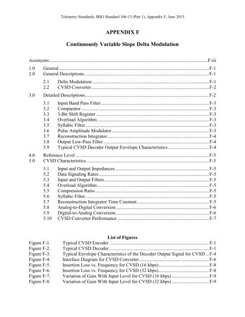
Telemetry Standards, IRIG Standard 106-13 (Part 1), <strong>Appendix</strong> F, June 2013<br />
APPENDIX F<br />
<strong>Continuously</strong> <strong>Variable</strong> <strong>Slope</strong> <strong>Delta</strong> <strong>Modulation</strong><br />
Acronyms .................................................................................................................................... F-iii<br />
1.0 General ............................................................................................................................. F-1<br />
2.0 General Descriptions ........................................................................................................ F-1<br />
2.1 <strong>Delta</strong> <strong>Modulation</strong> ................................................................................................. F-1<br />
2.2 CVSD Converter .................................................................................................. F-2<br />
3.0 Detailed Descriptions ....................................................................................................... F-2<br />
3.1 Input Band Pass Filter .......................................................................................... F-3<br />
3.2 Comparator .......................................................................................................... F-3<br />
3.3 3-Bit Shift Register .............................................................................................. F-3<br />
3.4 Overload Algorithm ............................................................................................. F-3<br />
3.5 Syllabic Filter ....................................................................................................... F-3<br />
3.6 Pulse Amplitude Modulator ................................................................................. F-3<br />
3.7 Reconstruction Integrator ..................................................................................... F-4<br />
3.8 Output Low-Pass Filter ........................................................................................ F-4<br />
3.9 Typical CVSD Decoder Output Envelope Characteristics .................................. F-4<br />
4.0 Reference Level ............................................................................................................... F-5<br />
5.0 CVSD Characteristics ...................................................................................................... F-5<br />
5.1 Input and Output Impedances .............................................................................. F-5<br />
5.2 Data Signaling Rates ............................................................................................ F-5<br />
5.3 Input and Output Filters ....................................................................................... F-5<br />
5.4 Overload Algorithm ............................................................................................. F-5<br />
5.5 Compression Ratio ............................................................................................... F-5<br />
5.6 Syllabic Filter ....................................................................................................... F-5<br />
5.7 Reconstruction Integrator Time Constant ............................................................ F-5<br />
5.8 Analog-to-Digital Conversion ............................................................................. F-6<br />
5.9 Digital-to-Analog Conversion ............................................................................. F-6<br />
5.10 CVSD Converter Performance ............................................................................ F-7<br />
List of Figures<br />
Figure F-1. Typical CVSD Encoder ................................................................................... F-1<br />
Figure F-2. Typical CVSD Decoder ................................................................................... F-1<br />
Figure F-3. Typical Envelope Characteristics of the Decoder Output Signal for CVSD ... F-4<br />
Figure F-4. Interface Diagram for CVSD Converter .......................................................... F-6<br />
Figure F-5. Insertion Loss vs. Frequency for CVSD (16 kbps) .......................................... F-8<br />
Figure F-6. Insertion Loss vs. Frequency for CVSD (32 kbps) .......................................... F-8<br />
Figure F-7. Variation of Gain With Input Level for CVSD (16 kbps) ............................... F-9<br />
Figure F-8. Variation of Gain With Input Level for CVSD (32 kbps) ............................... F-9
Telemetry Standards, IRIG Standard 106-13 (Part 1), <strong>Appendix</strong> F, June 2013<br />
Figure F-9. Signal to Quantizing Noise Ratio vs. Input Level for CVSD (16 kbps) ........ F-10<br />
Figure F-10. Signal to Quantizing Noise Ratio vs. Input Level for CVSD (32 kbps) ........ F-10<br />
Figure F-11. Signal to Quantizing Noise Ratio vs. Frequency for CVSD (16 Kbps) ........ F-11<br />
Figure F-12. Signal to Quantizing Noise Ratio vs. Frequency for CVSD (32 Kbps) ........ F-11<br />
List of Tables<br />
Table F-1. Decoder Reference Digital Patters for CVSD ................................................. F-6<br />
Table F-2. Insertion Loss Limits for CVSD ...................................................................... F-7<br />
Table F-3. Idle Channel Noise Limits for CVSD .............................................................. F-9<br />
F-ii
Telemetry Standards, IRIG Standard 106-13 (Part 1), <strong>Appendix</strong> F, June 2013<br />
Acronyms<br />
CVSD<br />
dB<br />
Hz<br />
kbps<br />
ms<br />
PAM<br />
continuously variable slope data<br />
decibel<br />
hertz<br />
kilobits per second<br />
microsecond<br />
pulse amplitude modulator<br />
F-iii
Telemetry Standards, IRIG Standard 106-13 (Part 1), <strong>Appendix</strong> F, June 2013<br />
This page intentionally left blank.<br />
F-iv
Telemetry Standards, IRIG Standard 106-13 (Part 1), <strong>Appendix</strong> F, June 2013<br />
1.0 General<br />
APPENDIX F<br />
<strong>Continuously</strong> <strong>Variable</strong> <strong>Slope</strong> <strong>Delta</strong> <strong>Modulation</strong><br />
The continuously variable slope delta (CVSD) modulation is a nonlinear, sampled data,<br />
feedback system which accepts a band-limited analog signal and encodes it into binary form for<br />
transmission through a digital channel. At the receiver, the binary signal is decoded into a close<br />
approximation of the original analog signal. A typical CVSD converter consisting of an encoder<br />
and decoder is shown in Figure F-1 and Figure F-2.<br />
Figure F-1.<br />
Typical CVSD Encoder<br />
Figure F-2.<br />
Typical CVSD Decoder<br />
2.0 General Descriptions<br />
A general description of the delta modulation and the CVSD converter can be found in<br />
the following subparagraphs.<br />
2.1 <strong>Delta</strong> <strong>Modulation</strong><br />
<strong>Delta</strong> modulation is an A-D conversion technique resulting in a form of digital pulse<br />
modulation. A delta modulator periodically samples the amplitude of a band-limited analog<br />
F-1
Telemetry Standards, IRIG Standard 106-13 (Part 1), <strong>Appendix</strong> F, June 2013<br />
signal, and the amplitude differences of two adjacent samples are coded into n-bit code words.<br />
This nonlinear, sampled-data feedback system then transmits the encoded bit stream through a<br />
digital channel. At the receiving end, an integrating network converts the delta-modulated bit<br />
stream through a decoding process into a close approximation of the original analog signal.<br />
2.2 CVSD Converter<br />
A typical CVSD converter consists of an encoder and a decoder (see Figure F-1 and<br />
Figure F-2). The analog input signal of the CVSD encoder is band-limited by the input band,<br />
pass filter. The CVSD encoder compares the band-limited analog input signal with an analog<br />
feedback approximation signal generated at the reconstruction integrator output. The digital<br />
output signal of the encoder is the output of the first register in the “run-of-three” counter. The<br />
digital output signal is transmitted at the clock (sample) rate and will equal “1” if the analog<br />
input signal is greater than or equal to the analog feedback signal at the instant of sampling. For<br />
this value of the digital output signal, the pulse amplitude modulator (PAM) applies a positive<br />
feedback pulse to the reconstruction integrator; otherwise, a negative pulse is applied. This<br />
function is accomplished by the polarity control signal, which is equal to the digital encoder<br />
output signal. The amplitude of the feedback pulse is derived by means of a 3-bit shift register,<br />
logic sensing for overload, and a syllabic lowpass filter. When a string of three consecutive ones<br />
or zeros appears at the digital output, a discrete voltage level is applied to the syllabic filter, and<br />
the positive feedback pulse amplitude increases until the overload string is broken. In such an<br />
event, ground potential is fed to the filter by the overload algorithm, forcing a decrease in the<br />
amplitude of the slope voltage out of the syllabic filter. The encoder and decoder have identical<br />
characteristics except for the comparator and filter functions.<br />
The CVSD decoder consists of the input band pass filter, shift register, overload<br />
algorithm, syllabic filter, PAM and reconstruction integrator used in the encoder, and an output<br />
low-pass filter. The decoder performs the inverse function of the encoder and regenerates speech<br />
by passing the analog output signal of the reconstruction integrator through the low-pass filter.<br />
Other characteristics optimize the CVSD modulation technique for voice signals. These<br />
characteristics include the following.<br />
a. Changes in the slope of the analog input signal determine the step-size changes of the<br />
digital output signal.<br />
b. The feedback loop is adaptive to the extent that the loop provides continuous or smoothly<br />
incremental changes in step size.<br />
c. Companding is performed at a syllabic rate to extend the dynamic range of the analog<br />
input signal.<br />
d. The reconstruction integrator is of the exponential (leaky) type to reduce the effects of<br />
digital errors.<br />
3.0 Detailed Descriptions<br />
The characteristics described in subparagraphs 3.1 through 3.9 are in addition to those<br />
specified in Section 5.0 and are for guidance only.<br />
F-2
Telemetry Standards, IRIG Standard 106-13 (Part 1), <strong>Appendix</strong> F, June 2013<br />
3.1 Input Band Pass Filter<br />
The input filter provides band-limiting and is typically a second- or higher-order filter<br />
(see Figure F-1).<br />
3.2 Comparator<br />
The comparator compares the band-limited analog input signal from the filter with the<br />
output signal of the reconstruction integrator (see Figure F-1). This comparison produces the<br />
digital error signal input to the 3-bit shift register. The transfer characteristic of the comparator<br />
is such that the difference between the two input signals causes the output signal to be driven to<br />
saturation in the direction of the sign of the difference.<br />
3.3 3-Bit Shift Register<br />
The 3-bit shift register acts as a sampler which clocks the digital error signal from the<br />
comparator at the specified data signaling rate and stores the current samples and two previous<br />
samples of the error signal (see Figure F-1 and Figure F-2). The digital output signal is a binary<br />
signal having the same polarity as the input signal from the comparator at the time of the clock<br />
signal. The digital output signal is also the digital output of the encoder and is referred to as the<br />
baseband signal. Further processing for transmission such as conditioned diphase modulation<br />
may be applied to the baseband signal. It is necessary that the inverse of any such processing be<br />
accomplished and the baseband signal restored before the CVSD decoding process is attempted.<br />
3.4 Overload Algorithm<br />
The overload algorithm operates on the output of the 3-bit shift register (X, Y, Z) using<br />
the run-of-threes coincidence algorithm so that the algorithm output equals ( XYZ + XYZ ) (see<br />
Figure F-1 and Figure F-2). The output signal is a binary signal at the clock signaling rate and is<br />
true for one clock period following the detection of three like bits and false at all other times.<br />
3.5 Syllabic Filter<br />
The syllabic filter acts as a low-pass filter for the output signal from the overload<br />
algorithm (see Figure F-1 and Figure F-2). The slope-voltage output of the syllabic filter is the<br />
modulating input to the PAM. The step-function response of the syllabic filter is related to the<br />
syllabic rate of speech, is independent of the sampling rate, and is exponential in nature. When<br />
the overload algorithm output is true, a charging curve is applicable. When this output is false, a<br />
discharging curve is applicable.<br />
3.6 Pulse Amplitude Modulator<br />
The PAM operates with two input signals: the output signal from the syllabic filter and<br />
the digital signal from the 3-bit shift register (see Figure F-1 and Figure F-2). The syllabic filter<br />
output signal determines the amplitude of the PAM output signal and the signal from the 3-bit<br />
shift register is the polarity control that determines the direction, plus or minus, of the PAM<br />
output signal. The phrase “continuously variable” in CVSD is derived from the way the PAM<br />
output signal varies almost continuously.<br />
F-3
Telemetry Standards, IRIG Standard 106-13 (Part 1), <strong>Appendix</strong> F, June 2013<br />
3.7 Reconstruction Integrator<br />
The reconstruction integrator operates on the output signal of the PAM to produce an<br />
analog feedback signal to the comparator (or an output signal to the output low-pass filter in the<br />
receiver) that is an approximation of the analog input signal (see Figure F-1 and Figure F-2).<br />
3.8 Output Low-Pass Filter<br />
The output filter is a low-pass filter having a frequency response that typically has an<br />
asymptotic rolloff with a minimum slope of 40 decibels (dB) per octave, and a stopband rejection<br />
that is 45 dB or greater (see Figure F-2). The same output filter characteristic is used for encoder<br />
digital output signals of either 16 or 32 kilobits per second (kbps).<br />
3.9 Typical CVSD Decoder Output Envelope Characteristics<br />
For a resistance/capacitance circuit in the syllabic filter with time constants of 5<br />
microseconds (ms) for both charging and discharging, the envelope characteristics of the signal<br />
at the decoder output are shown in Figure F-3. For the case of switching the signal at the<br />
decoder input from the 0 percent run-of-threes digital pattern to the 30 percent run-of-threes<br />
digital pattern, the characteristic of the decoder output signal follows the resistance/capacitance<br />
charge curve. Note that the number of time constants required to reach the 90 percent charge<br />
point is 2.3, which gives a nominal charge time of 11.5 ms.<br />
Figure F-3.<br />
Typical Envelope Characteristics of the Decoder Output Signal for CVSD<br />
When switching the other way (from the 30 percent pattern to the 0 percent pattern), the<br />
amplitude at the beginning of discharging is, at the first moment of switching, higher (by a factor<br />
of 16) than the final value which is reached asymptotically. The final value equals -24 dBm0,<br />
that is, 0.03. Therefore, the amplitude at the beginning of discharging is 0.48 (percent run-ofthrees<br />
= 0). Note that the number of time constants required to reach the 10 percent point on the<br />
discharge curve is 1.57, which gives a nominal discharge time of 7.8 ms.<br />
F-4
Telemetry Standards, IRIG Standard 106-13 (Part 1), <strong>Appendix</strong> F, June 2013<br />
4.0 Reference Level<br />
The decoder analog output level with the 16 and 32 kbps, 30 percent run-of-threes<br />
reference digital pattern applied to the decoder input shall be the reference level for the CVSD<br />
requirements of this standard and shall be designated 0 dBm0 (see Subparagraph 5.9.1).<br />
5.0 CVSD Characteristics<br />
The characteristics of CVSD are described in the following subparagraphs.<br />
5.1 Input and Output Impedances<br />
The analog input and output impedances for CVSD converters are not standardized.<br />
These impedances depend upon the application of the converters.<br />
5.2 Data Signaling Rates<br />
The CVSD converter shall be capable of operating at 16 and 32 kbps.<br />
5.3 Input and Output Filters<br />
The analog input shall be band pass filtered. The analog output shall be low pass filtered.<br />
5.4 Overload Algorithm<br />
Details of input and output filers, consistent with the CVSD performance<br />
requirements of this standard, will be determined in applicable equipment<br />
specifications based on validated requirements<br />
A 3-bit shift register shall be used for the CVSD encoder and decoder (see Figure F-1 and<br />
Figure F-2). The overload logic shall operate on the output of this shift register using the run-ofthrees<br />
coincidence algorithm. The algorithm output signal shall be a binary signal at the datasignaling<br />
rate. This signal shall be true for one clock period following the detection of three like<br />
bits (all 0s or all 1s) and false at all other times.<br />
5.5 Compression Ratio<br />
The compression ratio shall be nominally 16:1 with a maximum of 21:1 and a minimum<br />
of 12:1. The maximum slope voltage shall be measured at the output of the syllabic filter for a<br />
30 percent run-of-threes digital pattern. The minimum slope voltage shall be measured at the<br />
output of the syllabic filter for a 0 percent run-of-threes digital pattern.<br />
5.6 Syllabic Filter<br />
The syllabic filter shall have a time constant of 5 ms ±1. The step function response of<br />
the syllabic filter shall be exponential in nature. When the output of the overload algorithm is<br />
true, a charge curve shall be applicable. When the output of the overload algorithm is false, a<br />
discharge curve shall be applicable.<br />
5.7 Reconstruction Integrator Time Constant<br />
The reconstruction integrator shall have a time constant of 1 ms ±0.25.<br />
F-5
Telemetry Standards, IRIG Standard 106-13 (Part 1), <strong>Appendix</strong> F, June 2013<br />
5.8 Analog-to-Digital Conversion<br />
An 800-Hertz (Hz) ±10 signal at a 0 dBm0 level applied to the input of the encoder shall<br />
give a duty cycle of 0.30 at the algorithm output of the encoder shown in Figure F-1.<br />
5.9 Digital-to-Analog Conversion<br />
The characteristics of a digital-to-analog conversion are described in the following<br />
subparagraphs.<br />
5.9.1 Relation of Output to Input<br />
With the applicable reference digital patterns of Table F-1 applied to the digital input of<br />
the decoder as shown in Figure F-4, the analog output signal shall be 800 Hz ±10 at the levels<br />
shown in Table F-1, measured at the decoder output. These digital patterns, shown in<br />
hexadecimal form, shall be repeating sequences.<br />
Table F-1. Decoder Reference Digital Patters for CVSD<br />
Data Signaling Rate<br />
Run-of-threes<br />
Digital Pattern<br />
(kbps)<br />
(percent)<br />
Output (dBm0)<br />
16 DB492 0 -24±1<br />
32 DB54924AB6 0 -24±1<br />
16 FB412 30 0±1<br />
32 FDAA10255E 30 0±1<br />
Figure F-4.<br />
Interface Diagram for CVSD Converter<br />
5.9.2 Conversion Speed<br />
When the decoder input is switched from the 0 percent run-of-threes digital pattern to the<br />
30 percent run-of-threes digital pattern, the decoder output shall reach 90 percent of its final<br />
value within 9 to 14 ms. When the decoder input is switched from the 30 percent run-of-threes<br />
digital pattern to the 0 percent run-of-threes digital pattern, the decoder output shall reach 10<br />
percent of the 30 percent run-of-threes value within 6 to 9 ms. These values shall apply to both<br />
the 16- and 32-kbps data signaling rates.<br />
F-6
Telemetry Standards, IRIG Standard 106-13 (Part 1), <strong>Appendix</strong> F, June 2013<br />
5.10 CVSD Converter Performance<br />
The characteristics specified in subparagraphs 5.10.1 through 5.10.7 apply to one CVSD<br />
conversion process obtained by connecting the output of an encoder to the input of a decoder<br />
(see Figure F-4).<br />
Test signal frequencies that are submultiples of the data signaling rate shall be<br />
avoided by offsetting the nominal test frequency slightly; for example, an<br />
800-Hz test frequency could be offset to 804 Hz. This test frequency offset<br />
will avoid nonlinear distortion, which can cause measurement difficulties<br />
when CVSD is in tandem with pulse code modulation.<br />
5.10.1 Companding Speed<br />
When an 800-Hz ±10 sine wave signal at the encoder input is switched from -24 dBm0 to<br />
0 dBm0, the decoder output signal shall reach 90 percent of its final value within 9 to 14 ms.<br />
5.10.2 Insertion Loss<br />
The insertion loss between the encoder input and the decoder output shall be 0 dB ±2 dB<br />
with an 800 Hz ±10, 0 dBm0 input to the encoder.<br />
5.10.3 Insertion Loss vs. Frequency Characteristics<br />
The insertion loss between the encoder input and decoder output, relative to 800 Hz ±10<br />
measured with an input level of -15 dBm0 applied to the converter input, shall not exceed the<br />
limits indicated in Table F-2 and shown in Figure F-5 and Figure F-6.<br />
Rate (kbps)<br />
Table F-2. Insertion Loss Limits for CVSD<br />
Frequency (f) (Hz)<br />
16 f < 300<br />
300 ≤ f ≥ 1000<br />
1000 ≤ f ≥ 2600<br />
2600 ≤ f ≥ 4200<br />
4200 ≤ f<br />
32 f < 300<br />
300 ≤ f ≥ 1400<br />
1400 ≤ f ≥ 2600<br />
2600 ≤ f ≥ 3400<br />
3400 ≤ f ≥ 4200<br />
4200 ≤ f<br />
Insertion Loss (dB)<br />
(Referenced to 800 Hz)<br />
≥ -1.5<br />
-1.5 to 1.5<br />
-5 to 1.5<br />
≥ -5<br />
≥ 25<br />
≥ -1<br />
-1 to 1<br />
3 to 1<br />
3 to 2<br />
≥ -3<br />
≥ 25<br />
F-7
Telemetry Standards, IRIG Standard 106-13 (Part 1), <strong>Appendix</strong> F, June 2013<br />
Figure F-5.<br />
Insertion Loss vs. Frequency for CVSD (16 kbps)<br />
Figure F-6.<br />
Insertion Loss vs. Frequency for CVSD (32 kbps)<br />
5.10.4 Variation of Gain With Input Level<br />
The variation in output level, relative to the value at -15 dBm0 input, shall be within the<br />
limits of Figure F-7 and Figure F-8 for an input frequency of 800 Hz ±10.<br />
F-8
Telemetry Standards, IRIG Standard 106-13 (Part 1), <strong>Appendix</strong> F, June 2013<br />
Figure F-7.<br />
Variation of Gain With Input Level for CVSD (16 kbps)<br />
Figure F-8.<br />
Variation of Gain With Input Level for CVSD (32 kbps)<br />
5.10.5 Idle Channel Noise<br />
The idle channel noise shall not exceed the limits shown in Table F-3 when measured at<br />
the CVSD decoder output.<br />
Table F-3. Idle Channel Noise Limits for CVSD<br />
Data Signaling Rate (kbps) Idle Channel Noise (dBm0)<br />
16 -40<br />
32 -50<br />
5.10.6 Variation of Quantizing Noise With Input Level<br />
The minimum signal to quantizing noise ratio over the input signal level range shall be<br />
above the limits of Figure F-9 and Figure F-10. The noise ratio shall be measured with flat<br />
weighting (unweighted) at the decoder output with a nominal 800-Hz ±10 sine wave test signal<br />
at the encoder input.<br />
F-9
Telemetry Standards, IRIG Standard 106-13 (Part 1), <strong>Appendix</strong> F, June 2013<br />
Figure F-9.<br />
Signal to Quantizing Noise Ratio vs. Input Level for CVSD (16 kbps)<br />
Figure F-10. Signal to Quantizing Noise Ratio vs. Input Level for CVSD (32 kbps)<br />
5.10.7 Variation of Quantizing Noise With Frequency<br />
The minimum signal to quantizing noise ratio over the input frequency range shall be<br />
above the limits of Figure F-11 and Figure F-12. The noise ratio shall be measured with flat<br />
weighting (unweighted) at the decoder output with a sine wave test signal of -15 dBm0.<br />
F-10
Telemetry Standards, IRIG Standard 106-13 (Part 1), <strong>Appendix</strong> F, June 2013<br />
Figure F-11. Signal to Quantizing Noise Ratio vs. Frequency for CVSD (16 Kbps)<br />
Figure F-12. Signal to Quantizing Noise Ratio vs. Frequency for CVSD (32 Kbps)<br />
F-11
Telemetry Standards, IRIG Standard 106-13 (Part 1), <strong>Appendix</strong> F, June 2013<br />
**** END OF APPENDIX F ****<br />
F-12