Kamewa controllable pitch propeller - Martin's Marine Engineering ...
Kamewa controllable pitch propeller - Martin's Marine Engineering ...
Kamewa controllable pitch propeller - Martin's Marine Engineering ...

Create successful ePaper yourself
Turn your PDF publications into a flip-book with our unique Google optimized e-Paper software.
Fact Sheet<br />
Rolls-Royce <strong>propeller</strong>s<br />
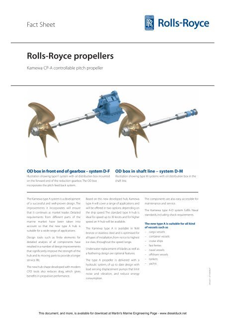
<strong>Kamewa</strong> CP-A <strong>controllable</strong> <strong>pitch</strong> <strong>propeller</strong><br />
OD box in front end of gearbox – system D-F<br />
Illustration showing type F system with oil distribution box mounted<br />
on the forward end of the reduction gearbox. The OD box<br />
incorporates the <strong>pitch</strong> feed back system.<br />
OD box in shaft line – system D-M<br />
Illustration showing type M systems with oil distribution box in the<br />
shaft line.<br />
The <strong>Kamewa</strong> type A system is a development<br />
of a successful and well-proven design. The<br />
improvements it incorporates will ensure<br />
that it continues as market leader. Detailed<br />
requirements from different parts of the<br />
marine market have been taken into<br />
account so that the new type A hub is<br />
suitable for a wide range of applications.<br />
Design tools such as finite elements for<br />
detailed analysis of all components have<br />
resulted in a number of design improvements<br />
that significantly improve the strength of the<br />
hub and its moving parts to provide a longer<br />
service life.<br />
The new hub shape developed with modern<br />
CFD tools also reduces drag, which gives<br />
benefits in propulsive performance.<br />
Based on this new developed hub, <strong>Kamewa</strong><br />
type A will cover a range of applications and<br />
will be offered in two options depending on<br />
the ship speed. The standard type A hub is<br />
ideal for speed up to 30 knots and for higher<br />
speed an H hub will be available.<br />
The <strong>Kamewa</strong> type A is available in NiAl<br />
bronze or stainless steel and is optimised for<br />
all types of installation, from no ice to highest<br />
ice class, throughout the speed range.<br />
Underwater replacement of blades as well as<br />
a feathering design are optional features.<br />
The type A <strong>propeller</strong> is delivered with a<br />
hydraulic system, of up to date design with<br />
load sensing displacement pumps that limit<br />
noise and vibration, and reduce energy<br />
consumption.<br />
The components are also easy accessible for<br />
maintenance and service.<br />
The <strong>Kamewa</strong> type A-D system fulfils Naval<br />
standards, including shock requirements.<br />
The new type A is suitable for all kind<br />
of vessels such as<br />
– cargo vessels<br />
– container vessels<br />
– cruise ships<br />
– fast ferries<br />
– naval vessels<br />
– offshore vessels<br />
– tankers<br />
– yachts<br />
04.KaUl-1 of 4-08.06.07<br />
This document, and more, is available for download at <strong>Martin's</strong> <strong>Marine</strong> <strong>Engineering</strong> Page - www.dieselduck.net
Fact Sheet<br />
Main dimensions<br />
4-bladed <strong>propeller</strong>s<br />
NAV/ ** ) *** )<br />
HUB A B C D E F Gmin G H Weight Weight<br />
46 585 190 48 460 280 415 140 270 65 280 270<br />
50 640 210 53 500 300 463 150 280 65 370 350<br />
55 700 220 58 550 330 500 170 290 65 490 470<br />
60 765 240 63 600 365 547 185 300 65 635 610<br />
66 840 275 70 660 400 612 205 325 80 850 810<br />
72 917 300 76 720 435 650 215 350 80 1110 1050<br />
79 1005 320 83 790 480 700 235 375 80 1455 1390<br />
86 1095 345 90 860 520 772 255 400 95 1875 1790<br />
94 1170 375 97 940 600 840 280 425 95 2450 2340<br />
102 1265 405 107 1020 650 920 305 650 110 3040 2985<br />
111 1380 440 117 1110 705 1000 330 675 110 3920 3850<br />
121 1502 482 127 1210 770 1090 355 750 125 5075 4984<br />
132 1640 525 138 1320 840 1180 395 775 125 6590 6470<br />
144 1780 575 150 1440 915 1285 420 850 150 8555 8400<br />
150 1880 595 160 1500 960 1340 440 835 150 9670 9495<br />
157 1969 625 165 1570 1007 1400 460 875 150 11090 10890<br />
164 2055 655 172 1640 1050 1450 480 900 150 12580 12410<br />
171 2145 685 180 1710 1095 1500 500 925 175 14260 14070<br />
179 2245 715 188 1790 1150 1570 520 950 175 16360 16135<br />
186 2330 730 195 1860 1195 1640 540 975 175 18350 18105<br />
194 2435 772 204 1940 1245 1710 570 1050 175 20820 20540<br />
202 2535 805 212 2020 1295 1820 585 1075 175 23510 23190<br />
211 2645 840 222 2110 1355 1900 610 1125 200 26790 26430<br />
220 2760 875 230 2200 1410 1980 640 1150 200 30370 29955<br />
Weight = Hub without blade flange<br />
Dimensions in the table are not<br />
binding. Right of alterations reserved.<br />
G min<br />
5-bladed <strong>propeller</strong>s<br />
G<br />
Hub designations<br />
Hub size<br />
Hub type<br />
Number of blades<br />
Type of actuor system<br />
Hub material<br />
Different options<br />
<strong>Kamewa</strong> 157 A / 4 - D / S / H<br />
Twin tube system<br />
Gmin and G = Dismounting space (see drwg. 154069)<br />
*) Incl. flange cover<br />
** ) Standard and ice hub<br />
*** )Nozzle hub<br />
A<br />
B<br />
C<br />
NAV/<br />
HUB A B C D E F Gmin G H Weight<br />
60 707 215 63 600 365 560 165 280 65 555<br />
66 776 235 70 660 400 620 185 305 80 745<br />
72 845 255 76 720 435 670 195 330 80 970<br />
79 924 277 83 790 480 720 215 355 80 1275<br />
86 1007 302 90 860 520 787 225 370 95 1645<br />
94 1095 325 97 940 600 860 250 395 95 2105<br />
102 1191 355 107 1020 650 935 275 620 110 2745<br />
111 1295 385 117 1110 705 1020 295 640 110 3545<br />
121 1417 425 127 1210 770 1090 320 715 125 4500<br />
132 1542 460 138 1320 840 1210 350 730 125 5840<br />
144 1755 575 150 1440 915 1285 420 850 150 7735<br />
150 1824 595 160 1500 960 1340 440 835 150 8750<br />
157 1912 625 165 1570 1007 1400 460 875 150 9715<br />
164 1999 655 172 1640 1050 1450 480 900 150 11060<br />
171 2086 685 180 1710 1095 1500 500 925 175 12540<br />
179 2182 715 188 1790 1150 1570 520 950 175 14380<br />
186 2254 730 195 1860 1195 1640 540 975 175 16130<br />
194 2362 772 204 1940 1245 1710 570 1050 175 18300<br />
202 2460 805 212 2020 1295 1820 585 1075 175 20670<br />
211 2569 840 222 2110 1355 1900 610 1125 200 23550<br />
220 2678 875 230 2200 1410 1980 640 1150 200 26720<br />
Weight = Hub without blade flange<br />
Dimensions in the table are not<br />
binding. Right of alterations reserved.<br />
D<br />
E<br />
H<br />
* ) F<br />
04.KaUl-2 of 4-08.06.07<br />
This document, and more, is available for download at <strong>Martin's</strong> <strong>Marine</strong> <strong>Engineering</strong> Page - www.dieselduck.net
Fact Sheet<br />
There are two OD box installation alternatives for <strong>Kamewa</strong> CPP systems<br />
- type F0 and type M0<br />
Installation system F<br />
The oil distribution box is mounted on the forward end of the reduction gearbox. Additional intermediate shafts can be arranged between the<br />
<strong>propeller</strong> shaft and the gearbox. The OD box also<br />
incorporates the <strong>pitch</strong> feed back system.<br />
Reduction gearbox<br />
Type F0 requires the minimum overall<br />
installation space and is therefore the most favourable<br />
Split distance ring<br />
solution.<br />
It is possible to remove the reduction<br />
gearbox without docking the ship.<br />
Hydraulic sleeve-, or flange-coupling<br />
Table / pictures (Dimensions in mm)<br />
B=Minimum distance for OD box dismantling<br />
OD box, system F<br />
F<br />
T.O-BOX/<br />
O.D.-BOX A B C D E F Weight<br />
35 355 121 78 240 210 233 50<br />
50 481 116 77 294 274 263 90<br />
70 651 170 105 400 380 314 205<br />
100 860 221 130 510 470 364 330<br />
140 1079 270 175 625 620 439 640<br />
C<br />
D<br />
A<br />
B<br />
=<br />
E<br />
=<br />
Installation system M<br />
A separate shaft carries the oil distribution box and additional intermediate shafts can be arranged<br />
between the <strong>propeller</strong> shaft and the OD box shaft. The forward part of the OD box shaft<br />
incorporates the <strong>pitch</strong> feed back mechanism and has an integral flange connecting to the engine<br />
output flange, reduction gearbox, or to solid intermediate shafts.<br />
Table / pictures (Dimensions in mm)<br />
* Coupling placed on <strong>propeller</strong> shaft at installation<br />
** Coupling placed on OD box shaft at installation<br />
OD box, system M<br />
Forward end of <strong>propeller</strong><br />
or intermediate shaft<br />
D L L<br />
Size Max D1 D2 min* min**<br />
230 230 395 450 1350 1900<br />
300 300 185 550 1620 2200<br />
380 380 595 685 1910 2700<br />
450 450 695 795 2140 3000<br />
550 550 830 950 2400 3500<br />
620 620 930 1100 3000 4200<br />
700 700 1080 1240 3200 4700<br />
900 900 1370 1560 4000 5800<br />
(Dimensions in mm)<br />
* Coupling placed on <strong>propeller</strong><br />
shaft at installation<br />
** Coupling placed on OD box at<br />
installation<br />
Split distance ring<br />
L min/OD box shaft<br />
Hydraulic sleeve coupling<br />
Integral shaft flange<br />
D1 D2<br />
D max<br />
OD box<br />
Feedback box<br />
(electronic control system)<br />
04.KaUl-3 of 4-08.06.07<br />
This document, and more, is available for download at <strong>Martin's</strong> <strong>Marine</strong> <strong>Engineering</strong> Page - www.dieselduck.net
Fact Sheet<br />
The hydraulic system<br />
The power pack unit is state of the art design equipped with two<br />
redundant electric motor driven pumps, oil tank, main <strong>pitch</strong> control<br />
valves and all other necessary valves, filter, and cooler. Sensors are<br />
integral parts of the unit.<br />
Main pumps<br />
If the electric pumps are used as main pumps, one of the pumps is<br />
used as main pump unit while the other is set to stand-by. The<br />
electrical main pump supplies oil pressure for the <strong>pitch</strong> control and<br />
the stand-by pump will automatically start if the oil pressure drops<br />
below a pre-set level.<br />
The two electrically driven pumps are used as main pumps or<br />
stand-by depending if the hydraulic system is equipped with a PTO<br />
driven pump or not.<br />
The electrical pumps are of load sensing variable displacement type.<br />
Their special features are to give flow and oil pressure to the hydraulic<br />
system only when needed, and when not needed they are in idle<br />
mode. This feature minimises not only noise and vibration but it also<br />
provides pump power savings.<br />
A continuously running double pump unit maintains the static oil<br />
pressure.This pump unit creates the pressure both for the lubrication<br />
and static pressure system in the hub as well as running the oil cooler<br />
and filtration system.<br />
Twin-tube system<br />
Oil is transferred between the oil distribution box and <strong>propeller</strong> hub<br />
via a twin-tube system. Oil for hub lubrication is transmitted via the<br />
shaft bore outside the twin-tube.<br />
HPP size A B C D E F G Min service space Weight without oil Weight with oil<br />
150 lit 1060 mm 720 mm 1360 mm 980 mm 825 mm 650 mm ø22 mm 1500 mm 1000 kg 1110 kg<br />
300 lit 1120 mm 930 mm 1510 mm 1060 mm 1130 mm 830 mm ø22 mm 1750 mm 1200 kg 1420 kg<br />
500 lit 1360 mm 1090 mm 1620 mm 1240 mm 1220 mm 990 mm ø22 mm 1800 mm 1350 kg 1700 kg<br />
700 lit 1360 mm 1090 mm 1780 mm 1240 mm 1420 mm 990 mm ø22 mm 1950 mm 1450 kg 1950 kg<br />
1000 lit - mm - mm - mm - mm - mm - mm ø- mm - mm - kg - kg<br />
Dimensions in the table are not binding.<br />
Right of alterations reserved.<br />
This is only<br />
for size 150 lit.<br />
C<br />
Min service space<br />
D<br />
øG (4x)<br />
F<br />
75<br />
A<br />
B<br />
E<br />
Hydraulic power pack, with instrument and valves<br />
Pitch setting pumps, of variable load sense type<br />
04.KaUl-4 of 4-08.06.07<br />
Rolls-Royce AB<br />
P.O. Box 1010<br />
SE-681 29 Kristinehamn, Sweden<br />
Tel: +46 550 840 00 Fax: +46 550 181 90<br />
www.rolls-royce.com<br />
© 2007 Rolls-Royce plc<br />
Whilst this information is given in good faith, no<br />
warranty or representation is given concerning such<br />
information, which must not be taken as establishing<br />
any contractual or other commitment binding upon<br />
Rolls-Royce plc or any of its subsidiary or associated<br />
companies.<br />
This document, and more, is available for download at <strong>Martin's</strong> <strong>Marine</strong> <strong>Engineering</strong> Page - www.dieselduck.net