FLOWSIC600 Ultrasonic Gas Flow Meter
FLOWSIC600 Ultrasonic Gas Flow Meter
FLOWSIC600 Ultrasonic Gas Flow Meter

Create successful ePaper yourself
Turn your PDF publications into a flip-book with our unique Google optimized e-Paper software.
Newly Approved<br />
According to MID<br />
P r o d u c t I n f o r m at i o n<br />
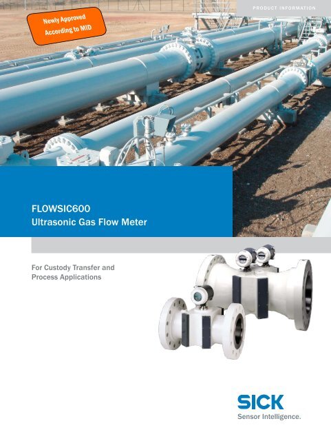
<strong>FLOWSIC600</strong><br />
<strong>Ultrasonic</strong> <strong>Gas</strong> <strong>Flow</strong> <strong>Meter</strong><br />
For Custody Transfer and<br />
Process Applications
<strong>FLOWSIC600</strong><br />
<strong>Gas</strong> flow measurement for<br />
process and custody applications<br />
A r e a s o f A p p l i c at i o n<br />
• Fiscal metering<br />
• Natural gas production, transportation, distribution<br />
and storage<br />
• Onshore and offshore applications<br />
• Dry, wet, corrosive and abrasive gases<br />
• Process control<br />
• Power plants, refineries and chemical industry<br />
• Steam and cryogenic<br />
• Process gases like N 2 , O 2 , H 2 , CO 2 , Cl 2 etc.<br />
• <strong>Gas</strong>es like sour gas or biogas with high H 2 S content<br />
F L O W S I C 6 0 0<br />
2 - Pat h<br />
F L O W S I C 6 0 0<br />
4 - Pat h<br />
F L O W S I C 6 0 0<br />
2 p l e x<br />
F L O W S I C 6 0 0<br />
Q u a t r o<br />
• 2 path<br />
• 2" ... 48"/<br />
DN50 ... DN1200<br />
• Uncertainties of ±1%<br />
• Integrated performance<br />
monitoring<br />
1)<br />
CBM … Condition Based Maintenance<br />
• 4 path<br />
• 3" ... 48"/<br />
DN80 ... DN1200<br />
• Uncertainty of ±0.2%<br />
• Integrated performance<br />
monitoring<br />
• 4 + 1 path<br />
• 3" ... 48"/<br />
DN80 ... DN1200<br />
• Uncertainty of ±0.2%<br />
• Integrated performance<br />
monitoring<br />
• CBM 1) by monitoring the<br />
installation close to the<br />
meter (contamination,<br />
blockage and pulsation)<br />
• Redundancy<br />
• 4 + 4 path<br />
• 3" ... 48"/<br />
DN80 ... DN1200<br />
• Uncertainty of ±0.2%<br />
• Integrated performance<br />
monitoring<br />
• 2 independent fiscal<br />
meters in one meter body<br />
• As 8 path version suitable<br />
for flow test facilities<br />
K e y F e at u r e s<br />
• Integrated real-time performance monitoring<br />
• New Software MEPAFLOW600 CBM 1)<br />
• 3 data logs (hourly, daily and weekly historical data)<br />
• 3 logbooks (alarms, warnings and parameter changes)<br />
• Highly efficient titanium transducers<br />
• Nearly insensitive to regulator noise<br />
• Operation even at atmospheric pressure<br />
• Transducers extractable under line pressure<br />
• Bi-directional measurement with no pressure drop<br />
• Compact 3D design with direct path layout<br />
• Rangeability greater than 100 : 1<br />
• No damage from over-ranging<br />
MEPAFLOW600 CBM supports commissioning, diagnosis, meter<br />
management and worldwide remote service.<br />
2 F L O W S I C 6 0 0 | S I C K 2 0 1 0 - 0 1<br />
Subject to change without notice
S y s t e m C o m p o n e n t s<br />
Signal Processing Unit (SPU)<br />
Pressure tap<br />
Marking for positive<br />
flow direction<br />
<strong>Meter</strong> body with flanges<br />
Flange<br />
<strong>Ultrasonic</strong> transducers<br />
L e a d i n g E d g e T r a n s d u c e r T e c h n o l o gy<br />
The heart of an ultrasonic flow meter is the ultrasonic transducer.<br />
The sealed, titanium transducer design, and the working<br />
frequencies of 135 kHz, 210 kHz and 350 kHz, permit<br />
using the <strong>FLOWSIC600</strong> in virtually all applications in gas flow<br />
metering – dry or wet, corrosive or ultrasonically noisy. This<br />
characteristics are complemented by a temperature range<br />
of –194 °C ... 280 °C (–317 °F ... 536 °F) and a pressure<br />
from 450 barg (6500 psig) down to ambient pressure.<br />
D i r e C t C h o r da l Pat h l ayo u t<br />
The direct chordal path layout incorporates distinct advantages.<br />
Since the signals are not reflected inside the meter,<br />
contamination or changes in wall roughness do not effect<br />
the signal strength and signal quality. For this reason long<br />
term stability of measurement performance and highest<br />
accuracy is achieved. Due to the direct chordal path layout,<br />
together with the excellent transducer characteristics, the<br />
<strong>FLOWSIC600</strong> has an enhanced immunity against control<br />
valve noise.<br />
2 0 1 0 - 0 1<br />
Subject to change without notice<br />
F L O W S I C 6 0 0 | S I C K<br />
3
8009840/2010-01 · DIV03 ∙ Printed in Germany ∙ Subject to change without notice.<br />
<strong>FLOWSIC600</strong><br />
Technical Data<br />
<strong>Meter</strong> characteristics<br />
Nominal size <strong>Flow</strong> rate [m 3 /h] <strong>Flow</strong> rate [ft 3 /h] Max. velocity 1) Length<br />
Min. Max. Min. Max. [m/s] [ft/s] [mm] [in]<br />
DN 50 2" 6 400 210 14,000 65 213 150 5.91<br />
DN 80 3" 12 1,000 280 35,000 65 213 240 9.45<br />
DN 100 4" 20 1,600 460 57,000 60 197 300 11.81<br />
DN 150 6" 32 3,000 1,130 106,000 50 164 450 17.72<br />
DN 200 8" 40 4,500 1,410 159,000 45 148 600 23.62<br />
DN 250 10" 50 7,000 1,770 247,000 40 131 750 29.53<br />
DN 300 12" 65 8,000 2,300 283,000 33 108 900 35.43<br />
DN 350 14" 80 10,000 2,830 353,000 33 108 1,050 41.34<br />
DN 400 16" 120 14,000 4,240 494,000 33 108 1,200 47.24<br />
DN 450 18" 130 17,000 4,590 600,000 33 108 1,350 53.15<br />
DN 500 20" 200 20,000 7,060 706,000 33 108 1,500 59.06<br />
DN 600 24" 320 32,000 11,300 1,130,000 33 108 1,800 70.87<br />
DN 700 28" 650 40,000 22,950 1,413,000 30 98 1,400 55.12<br />
DN 750 30" 650 45,000 22,950 1,589,000 30 98 1,500 59,06<br />
DN 800 32" 800 50,000 28,250 1,766,000 30 98 1,600 62.99<br />
DN 900 36" 1,000 66,000 35,320 2,331,000 30 98 1,800 70.87<br />
DN 1000 40" 1,200 80,000 42,380 2,825,000 30 98 2,000 78.74<br />
DN 1050 42" 1,300 85,000 45,910 3,002,000 30 98 2,100 82.68<br />
DN 1100 44" 1,400 90,000 49,440 3,178,000 28 92 2,200 86.61<br />
DN 1200 48" 1,600 100,000 56,500 3,531,000 27 89 2,400 94.49<br />
<strong>Meter</strong> body material • Carbon steel 1.1120/A216WCC; 1.0420/ A105<br />
• Stainless steel 1.4408/ASME A351 Gr. CF 8M<br />
• Low temperature carbon steel 1.6220/A352; 1.0566/A350LF2<br />
• Duplex steel 1.4470/ASME A995 Gr.4A/UNS J92205<br />
Measuring parameters<br />
<strong>Gas</strong>es<br />
Natural gas, process gases, air<br />
Measured value<br />
Temperature<br />
Pressure range<br />
Volume flow (actual and standard), volume (actual and standard), velocity of gas, speed of sound<br />
–40 °C ... +180 °C (–40 °F ... 365 °F); –194 °C ... +280 °C (–317 °F ... 536 °F) on request<br />
0 barg ... 250 barg; up to 450 barg on request (0 ... 3600 psig; up to 6500 psig on request)<br />
Repeatability < 0.1 %<br />
Typical uncertainty 1 path: ± 2.0 % 2)<br />
Approvals<br />
Ex certification<br />
2 paths: ± 1.0 % 2)<br />
4 paths: ±0.5 % 3) dry calibrated<br />
±0.2 % 3) after flow calibration + adjustment with constant factor<br />
±0.1 % 3) after flow calibration and with polynomial correction<br />
ATEX: II 1/2G EEx de ib [ia] IIA or IIC T4<br />
CSA: Class I, Division 1, Groups D T4; Class I, Division 2, Groups D T4<br />
Class I, Division 1, Groups B,C,D T4; Class I, Division 2, Groups A, B, C, D T4<br />
Pattern approval MID, PTB, NMi, Measurement Canada, GOST, ...<br />
Conformities<br />
OIML R137-1, OIMLD11, A. G. A Report No. 9, API 21.1 (draft), ISO 17089-1 (draft)<br />
Electrical safety CE Enclosure rating: IP 65/IP 67<br />
Outputs and interfaces<br />
Analog output<br />
Digital outputs<br />
Interfaces<br />
Bus protocol<br />
Active/passive; optically isolated; 4 ... 20 mA; max. load = 250 Ω<br />
Passive, optically isolated, open collector or according NAMUR, f max = 6 kHz<br />
2 x RS485<br />
• Modbus ASCII/Modbus RTU<br />
• HART protocol<br />
1)<br />
When the piping configuration 2 (with flow straightener plate) is used, the velocity of gas must not exceed 40 m/s (131 ft/s) in the pipe<br />
2)<br />
Within Q t ... Q max with straight inlet/outlet section of 20D/3D or with flow straightener 10D/3D<br />
3)<br />
Within Q t ... Q max with non disturbed inlet/outlet section of 10D/3D<br />
SICK MAIHAK GmbH | Germany<br />
Nimburger Str. 11 | 79276 Reute | www.sick.com<br />
Phone +49 7641 469-0 | Fax +49 7641 469-1149 | info.pa@sick.de