Gas Burners RS 70/M - Power Equipment Company
Gas Burners RS 70/M - Power Equipment Company
Gas Burners RS 70/M - Power Equipment Company

You also want an ePaper? Increase the reach of your titles
YUMPU automatically turns print PDFs into web optimized ePapers that Google loves.
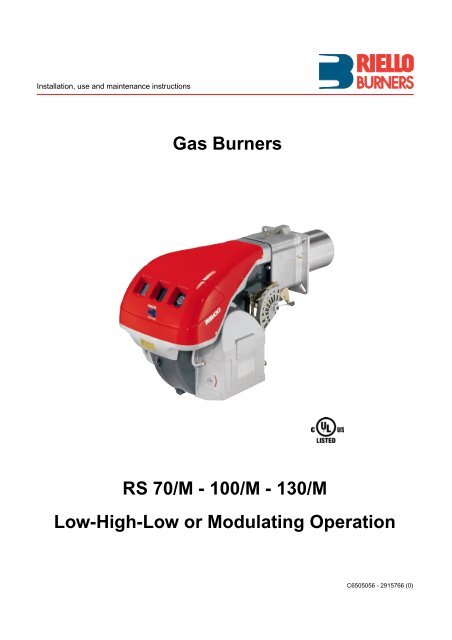
Installation, use and maintenance instructions<br />
<strong>Gas</strong> <strong>Burners</strong><br />
<strong>RS</strong> <strong>70</strong>/M - 100/M - 130/M<br />
Low-High-Low or Modulating Operation<br />
C6505056 - 2915766 (0)
CONTENTS<br />
TECHNICAL DATA . . . . . . . . . . . . . . . . . . . . . . . . . . . . . . page 3<br />
Burner models . . . . . . . . . . . . . . . . . . . . . . . . . . . . . . . . . . . . . . . 3<br />
Accessories . . . . . . . . . . . . . . . . . . . . . . . . . . . . . . . . . . . . . . . . . 3<br />
Burner description . . . . . . . . . . . . . . . . . . . . . . . . . . . . . . . . . . . . 4<br />
Packaging - Weight. . . . . . . . . . . . . . . . . . . . . . . . . . . . . . . . . . . . 4<br />
Max. dimensions. . . . . . . . . . . . . . . . . . . . . . . . . . . . . . . . . . . . . . 4<br />
Standard equipment . . . . . . . . . . . . . . . . . . . . . . . . . . . . . . . . . . . 4<br />
Firing rates . . . . . . . . . . . . . . . . . . . . . . . . . . . . . . . . . . . . . . . . . . 5<br />
Minimum furnace dimensions. . . . . . . . . . . . . . . . . . . . . . . . . . . . 5<br />
<strong>Gas</strong> pressure . . . . . . . . . . . . . . . . . . . . . . . . . . . . . . . . . . . . . . . . 6<br />
INSTALLATION . . . . . . . . . . . . . . . . . . . . . . . . . . . . . . . . . . . . . . 7<br />
Boiler plate . . . . . . . . . . . . . . . . . . . . . . . . . . . . . . . . . . . . . . . . . . 7<br />
Blast tube length . . . . . . . . . . . . . . . . . . . . . . . . . . . . . . . . . . . . . 7<br />
Securing the burner to the boiler . . . . . . . . . . . . . . . . . . . . . . . . . 7<br />
Ignition pilot adjustment . . . . . . . . . . . . . . . . . . . . . . . . . . . . . . . . 7<br />
Combustion head setting . . . . . . . . . . . . . . . . . . . . . . . . . . . . . . . 8<br />
<strong>Gas</strong> piping . . . . . . . . . . . . . . . . . . . . . . . . . . . . . . . . . . . . . . . . . . 9<br />
Adjustments before first firing. . . . . . . . . . . . . . . . . . . . . . . . . . . 10<br />
Servomotor. . . . . . . . . . . . . . . . . . . . . . . . . . . . . . . . . . . . . . . . . 11<br />
Burner starting . . . . . . . . . . . . . . . . . . . . . . . . . . . . . . . . . . . . . . 12<br />
Air pressure switch . . . . . . . . . . . . . . . . . . . . . . . . . . . . . . . . . . . 13<br />
High gas pressure switch . . . . . . . . . . . . . . . . . . . . . . . . . . . . . . 13<br />
Low gas pressure switch . . . . . . . . . . . . . . . . . . . . . . . . . . . . . . 13<br />
Flame present check . . . . . . . . . . . . . . . . . . . . . . . . . . . . . . . . . 13<br />
Maintenance. . . . . . . . . . . . . . . . . . . . . . . . . . . . . . . . . . . . . . . . 14<br />
Factory wiring diagram -burner mounted LFL . . . . . . . . . . . . . . 15<br />
Field wiring diagram - burner mounted LFL . . . . . . . . . . . . . . . . 16<br />
Factory wiring diagram - remote panel. . . . . . . . . . . . . . . . . . . . 17<br />
Appendix - Burner firing rates according to air density. . . . . . . . 18<br />
Siemens LFL control sequence of operations . . . . . . . . . . . . . . 19<br />
Siemens LFL controltroubleshooting guide . . . . . . . . . . . . . . . . 20<br />
Burner start up report. . . . . . . . . . . . . . . . . . . . . . . . . . . . . . . . . 21<br />
WARNING<br />
If you smell gas:<br />
• Do not touch any electrical items.<br />
• Open all windows.<br />
• Close all gas supply valves.<br />
• Contact your local gas authority immediately.<br />
Do not store flammable or hazardous materials in the vicinity<br />
of fuel burning appliances.<br />
Improper installation, adjustment, alteration, service or maintenance<br />
can cause property damage, personal injury or<br />
death. Refer to this manual for instructional or additional information.<br />
Consult a certified installer, service representative<br />
or the gas supplier for further assistance.<br />
Burner shall be installed in accordance with manufacturers<br />
requirements as outlined in this manual, local codes and authorities<br />
having juristiction.<br />
2
TECHNICAL DATA<br />
MODEL <strong>RS</strong> <strong>70</strong>/M <strong>RS</strong> 100/M <strong>RS</strong> 130/M<br />
Output (1) MAX. MBtu/hr<br />
kW<br />
1761 - 3084<br />
516 - 904<br />
2644 - 4405<br />
775 - 1291<br />
3521 - 5545<br />
1032 - 1625<br />
MIN.<br />
MBtu/hr<br />
kW<br />
512<br />
150<br />
5<strong>70</strong><br />
167<br />
607<br />
178<br />
Fuel<br />
Natural or Propane gas<br />
- Max. delivery SCFH 3084 4405 5545<br />
- Pressure at max. delivery (2) “WC 4.06 3.66 3.20<br />
Operation<br />
Low - high or modulating<br />
Standard applications<br />
Boilers: water, steam, thermal oil<br />
Ambient temperature °F 32 - 104 (0 - 40 °C)<br />
Combustion air temperature °F max 140 (60 °C)<br />
Main electrical supply (+/- 10%) V/Ph/Hz 208 - 230/460/575/3/60<br />
Fan motor<br />
Ignition transformer<br />
(1) Reference conditions: Ambient temperature 68 °F (20 °C) - Barometric pressure 394 “WC - Altitude 329 ft a.s.l.<br />
(2) Pressure at test point 16)(A)p.4, with zero pressure in the combustion chamber, with open gas ring 2)(B)p.8 an maximum burner output<br />
(2) Sound pressure measured in manufacturer’s combustion laboratory, with burner operating on test boiler and at maximum rated output.<br />
Burner models designations<br />
rpm<br />
W - HP<br />
V<br />
A<br />
V1 - V2<br />
I1 - I2<br />
3400<br />
1100 - 1.5<br />
208-230/460/575<br />
4.8/2.8/2.3<br />
3400<br />
1800 - 2.5<br />
208-230/460/575<br />
6.7/3.9/3.2<br />
120 V - 1 x 8 kV<br />
1.7 A - 20 mA<br />
3400<br />
2200 - 3<br />
208-230/460/575<br />
8.8/5.1/4.1<br />
Electrical power consumption W max 1400 2200 2600<br />
Electrical protection NEMA 1<br />
Noise levels (3) dBA 75 77 78,5<br />
Model Code Voltage Flame safeguard<br />
<strong>RS</strong> <strong>70</strong>/M<br />
<strong>RS</strong> 100/M<br />
<strong>RS</strong> 130/M<br />
C9524300 (378<strong>70</strong><strong>70</strong>)<br />
C9524301 (378<strong>70</strong><strong>70</strong>)<br />
C9624300 (378<strong>70</strong>72)<br />
C9624301 (378<strong>70</strong>72)<br />
C9525300 (37872<strong>70</strong>)<br />
C9525301 (37872<strong>70</strong>)<br />
C9625300 (3787272)<br />
C9625301 (3787272)<br />
C9526300 (37874<strong>70</strong>)<br />
C9526301 (37874<strong>70</strong>)<br />
C9626300 (3787472)<br />
C9626301 (3787472)<br />
208-230/460/3/60<br />
575/3/60<br />
208-230/460/3/60<br />
575/3/60<br />
208-230/460/3/60<br />
575/3/60<br />
208-230/460/3/60<br />
575/3/60<br />
208-230/460/3/60<br />
575/3/60<br />
208-230/460/3/60<br />
575/3/60<br />
Burner mounted<br />
Burner mounted<br />
Remote panel<br />
Remote panel<br />
Burner mounted<br />
Burner mounted<br />
Remote panel<br />
Remote panel<br />
Burner mounted<br />
Burner mounted<br />
Remote panel<br />
Remote panel<br />
ACCESSORIES (optional):<br />
• Kit for LPG operation: The kit allows the <strong>RS</strong> <strong>70</strong>-100-130/M burners to operate on LPG.<br />
BURNER <strong>RS</strong> <strong>70</strong>/M <strong>RS</strong> 100/M <strong>RS</strong> 130/M<br />
OUTPUT MBtu/hr 918 - 3084 1320 - 4405 1764 - 5545<br />
CODE 3010273 3010274 3010275<br />
• Kit for lengthening the combustion head<br />
L = Standard length<br />
L1 = Length obtainable with the kit<br />
COD. 3010259 L = 927 /32“ L1 = 155 /32“ • <strong>RS</strong> <strong>70</strong>/M<br />
COD. 3010260 L = 927 /32“ L1 = 155 /32“ • <strong>RS</strong> 100/M<br />
COD. 3010261 L = 11 1 /32“ L1 = 16 11 /32“ • <strong>RS</strong> 130/M<br />
• <strong>Gas</strong> train according to UL regulation: see page 9.<br />
Important:<br />
The installer is responsible for the supply and installation of any safety device(s) not indicated in this manual.<br />
3
(A)<br />
inch A (1) B C lbs<br />
<strong>RS</strong> <strong>70</strong>/M 46 27 /32“ - 52 5 /32“ 29 1 /8“ 27 1 /4“ 154<br />
<strong>RS</strong> 100/M 46 27 /32“ - 52 5 /32“ 29 1 /8“ 27 1 /4“ 161<br />
<strong>RS</strong> 130/M 46 27 /32“ - 52 5 /32“ 29 1 /8“ 27 1 /4“ 168<br />
(B)<br />
D2388<br />
D36<br />
BURNER DESCRIPTION (A)<br />
1 Combustion head<br />
2 Ignition electrode<br />
3 Screw for combustion head adjustment<br />
4 High gas pressure switch<br />
5 Servomotor controlling the gas butterfly valve and the<br />
air damper (by means of a variable profile cam mechanism).<br />
When the burner is stopped the air damper will be<br />
completely closed to reduce heat loss<br />
6 Plug-socket on flame rod cable<br />
7 Extensions for slide bars 15) (supplied by kit)<br />
8 Motor contactor and thermal overload with reset button<br />
9 <strong>Power</strong> switch for different operations:<br />
automatic - manual - off<br />
Button for:<br />
power increase - power reduction<br />
10 Terminal strip for electrical connection<br />
11 Pilot burner attachment<br />
12 Flame safeguard with lock-out pilot light and lock-out<br />
reset button<br />
13 Flame inspection window<br />
14 Low air pressure switch<br />
(differential operating type)<br />
15 Slide bars for opening the burner and inspecting the<br />
combustion head<br />
16 <strong>Gas</strong> pressure test point and head fixing screw<br />
17 Air pressure test point<br />
18 Flame sensor probe (flame rod)<br />
19 Pilot burner<br />
20 Air inlet to fan<br />
21 Screws securing fan to sleeve<br />
22 <strong>Gas</strong> input pipework<br />
23 <strong>Gas</strong> butterfly valve<br />
24 Boiler mounting flange<br />
25 Flame stability disk<br />
26 Air damper<br />
Two types of burner failure may occur:<br />
• FLAME SAFEGUARD LOCK-OUT:<br />
if the flame relay 12)(A) pushbutton lights up, it indicates<br />
that the burner is in lock-out.<br />
To reset, press the pushbutton.<br />
• MOTOR TRIP:<br />
release by pressing the pushbutton on thermal overload<br />
8)(A).<br />
PACKAGING - WEIGHT (B) - Approximate measurements<br />
• The burners are shipped skid mounted.<br />
Outer dimensions of packaging are indicated in (B).<br />
• The weight of the burner complete with packaging is<br />
indicated in Table (B).<br />
MAX. DIMENSIONS (C) - Approximate measurements<br />
The maximum dimensions of the burners are given in<br />
(C).<br />
Bear in mind that inspection of the combustion head<br />
requires the burner to be opened by withdrawing the<br />
rear part on the slide bars.<br />
The maximum dimension of the burner, when open is<br />
give by measurement I.<br />
(C)<br />
D731<br />
STANDARD EQUIPMENT<br />
1 - <strong>Gas</strong> train flange<br />
1 - Flange gasket<br />
4 - Flange fixing screws 3/8 W x 1”<br />
1 - Burner head gasket<br />
2 - Extensions 7)(A) for slide bars 15)(A)<br />
(for kit)<br />
4 - Screws to secure the burner flange to the boiler:<br />
1/2 W<br />
1 - Instruction booklet<br />
1 - Spare parts list<br />
inch A B C D E F (1) G H I (1) L M N O<br />
<strong>RS</strong> <strong>70</strong>/M 20 1 /8“ 11 21 /32“ 8 15 /32“ 21 27 /32“ 33 1 /16“ 9 27 /32“ - 15 5 /32“ 7 1 /32“ 16 29 /32“ 45 11 /16“ - 51 1 /32“ 8 13 /32“ 5 9 /32“ 8 11 /16“ 2”<br />
<strong>RS</strong> 100/M 20 3 /4“ 12 9 /32“ 8 15 /32“ 21 27 /32“ 33 1 /16“ 9 27 /32“ - 15 5 /32“ 7 1 /32“ 16 29 /32“ 45 11 /16“ - 51 1 /32“ 8 13 /32“ 5 9 /32“ 8 11 /16“ 2”<br />
<strong>RS</strong> 130/M 21 25 /32“ 13 5 /16“ 8 15 /32“ 21 27 /32“ 33 1 /16“ 11 1 /32“ - 16 11 /32“ 7 3 /32“ 16 29 /32“ 45 11 /16“ - 51 1 /32“ 8 13 /32“ 5 9 /32“ 8 11 /16“ 2”<br />
(1) Blast tube: short - long (obtainable with kit)<br />
4
combustion chamber pressure “WC<br />
combustion chamber pressure “WC<br />
<strong>RS</strong> <strong>70</strong>/M<br />
<strong>RS</strong> 100/M<br />
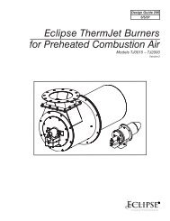
FIRING RATES (A)<br />
During operation, burner output varies between:<br />
• MAXIMUM OUTPUT, selected within area A,<br />
• and MINIMUM OUTPUT, which must not be lower<br />
than the minimum limit in the diagram.<br />
<strong>RS</strong> <strong>70</strong>/M = 512 MBtu/hr<br />
<strong>RS</strong> 100/M = 568 MBtu/hr<br />
<strong>RS</strong> 130/M = 607 MBtu/hr<br />
Note<br />
In order to utilize also area B (<strong>RS</strong> 130/M) it is necessary<br />
to perform the calibration of the combustion head as<br />
explained on page 7.<br />
Important<br />
The FIRING RATE area values have been obtained considering<br />
an ambient temperature of 68 °F (20 °C), and<br />
an atmospheric pressure of 394 “WC and with the combustion<br />
head adjusted as shown on page 8.<br />
Note:<br />
The FIRING RATE areas given in figure (A) have been<br />
reduced by 10% with respect to the maximum range that<br />
can be reached.<br />
Consult Appendix on page 18 for operation at different<br />
surrounding temperatures and/or altitudes.<br />
MINIMUM FURNACE DIMENSIONS (B)<br />
The firing rates were set in relation to certified test boilers.<br />
Figure (B) indicates the diameter and length of the test<br />
combustion chamber.<br />
Example:<br />
Output 2579 MBtu/hr:<br />
diameter = 24 inch; length 6.6 ft<br />
<strong>RS</strong> 130/M<br />
combustion chamber pressure “WC<br />
(A)<br />
D2389<br />
Diameter (inches)<br />
Furnace dimensions<br />
Length (ft)<br />
(B)<br />
D2919<br />
5
<strong>RS</strong> <strong>70</strong>/M<br />
∆p (“WC)<br />
MBtu/hr kW 1 2<br />
1761 516 1.65 0.08<br />
1952 572 1.89 0.08<br />
2139 627 2.20 0.12<br />
2330 683 2.52 0.12<br />
2518 738 2.87 0.12<br />
2<strong>70</strong>9 794 3.27 0.16<br />
2897 849 3.66 0.16<br />
3084 904 4.06 0.16<br />
<strong>RS</strong> 100/M<br />
∆p (“WC)<br />
MBtu/hr kW 1 2<br />
2631 771 1.46 0.16<br />
2880 844 1.65 0.16<br />
3125 916 1.97 0.20<br />
3371 988 2.28 0.20<br />
3617 1060 2.56 0.24<br />
3862 1132 2.87 0.28<br />
4108 1204 3.27 0.31<br />
4405 1291 3.66 0.31<br />
<strong>RS</strong> 130/M<br />
∆p (“WC)<br />
MBtu/hr kW 1 2<br />
3521 1032 1.50 0.39<br />
3825 1121 1.77 0.43<br />
4129 1210 2.01 0.51<br />
4432 1299 2.28 0.59<br />
4736 1388 2.56 0.67<br />
5036 1476 2.83 0.71<br />
5340 1565 3.11 0.75<br />
5545 1625 3.20 0.77<br />
(A)<br />
GAS PRESSURE<br />
The adjacent tables show minimum pressure losses<br />
along the gas supply line depending on the maximum<br />
burner output operation with natural gas.<br />
Column 1<br />
Pressure loss at combustion head.<br />
<strong>Gas</strong> pressure measured at test point 1)(B), with:<br />
• Combustion chamber at 0 “WC<br />
• Burner operating at maximum output<br />
• <strong>Gas</strong> ring 2)(B)p.8 adjusted as indicated in diagram<br />
(C)p.8.<br />
Column 2<br />
Pressure loss at gas butterfly valve 2)(B) with maximum<br />
opening: 90°.<br />
Calculate the approximate maximum output of the<br />
burner as follows:<br />
- subtract the combustion chamber pressure from the<br />
gas pressure measured at test point 1)(B).<br />
- Find the nearest pressure value to your result in column<br />
1 of the table for the burner in question.<br />
- Read off the corresponding output on the left.<br />
Example - <strong>RS</strong> 100/M:<br />
• Maximum output operation<br />
• Natural gas<br />
• <strong>Gas</strong> ring 2)(B)p.8 adjust as indicated in diagram<br />
(C)p.8<br />
• <strong>Gas</strong> pressure at test point 1)(B) = 3.15 “WC<br />
• Pressure in combustion chamber = 1.18 “WC<br />
3.15 - 1.18 = 1.97 “WC<br />
A maximum output of 2815 MBtu/hr shown in Table <strong>RS</strong><br />
100/M corresponds to 1.97 “WC pressure, column 1.<br />
This value serves as a rough guide, the effective delivery<br />
must be measured at the gas meter.<br />
To calculate the required gas pressure at test point<br />
1)(B), set the maximim output required from the burner<br />
operation:<br />
- Find the nearest output value in the table for the<br />
burner in question.<br />
- Read off the pressure at test point 1)(B) on the right in<br />
column 1.<br />
- Add this value to the estimated pressure in the combustion<br />
chamber.<br />
Example - <strong>RS</strong> 100/M:<br />
• Required burner maximum output operation:<br />
2815 MBTU/h<br />
• Natural gas<br />
• <strong>Gas</strong> ring 2)(B)p.8 adjust as diagram (C)p.8<br />
• <strong>Gas</strong> pressure at burner output of 2815 MBtu/hr, taken<br />
from table <strong>RS</strong> 100/M, column 1 = 1.97 “WC<br />
• Pressure in combustion chamber = 1.18 “WC<br />
1.97 + 1.18 = 3.15 “WC<br />
pressure required at test point 1)(B).<br />
(B)<br />
D2390<br />
6
(A)<br />
inch A B C<br />
<strong>RS</strong> <strong>70</strong>/M<br />
<strong>RS</strong> 100/M<br />
<strong>RS</strong> 130/M<br />
7 9 /32“<br />
7 9 /32“<br />
7 21 /32“<br />
1013 /16“ - 12 25 /32“<br />
10 13 /16“ - 12 25 /32“<br />
10 13 /16“ - 12 25 /32“<br />
1/2 W<br />
1/2 W<br />
1/2 W<br />
D455<br />
INSTALLATION<br />
BOILER PLATE (A)<br />
Drill the combustion chamber mounting plate as shown<br />
in (A). The position of the threaded holes can be marked<br />
using the burner head gasket supplied with the burner.<br />
BLAST TUBE LENGTH (B)<br />
The length of the blast tube must be selected according<br />
to the indications provided by the manufacturer of the<br />
boiler, it must be greater than the thickness of the boiler<br />
door complete with its insulation. The length available, L<br />
(inches), is as follows:<br />
Blast tube 12) <strong>RS</strong> <strong>70</strong>/M <strong>RS</strong> 100/M <strong>RS</strong> 130/M<br />
• short 9 27 /32“ 9 27 /32“ 11 1 /32“<br />
• long (with kit) 15 5 /32“ 15 5 /32“ 16 11 /32“<br />
For boilers with front flue passes 15) or flame inversion<br />
chambers, protective insulation material 13), must be<br />
inserted between the boiler refractory 14) and the blast<br />
tube 12).<br />
This protective insulation must not compromise the<br />
extraction of the blast tube.<br />
For boilers having a water-cooled front, the insulation<br />
13)-14) is not required unless it is required by the boiler<br />
manufacturer.<br />
(B)<br />
Ignition<br />
pilot<br />
Probe<br />
D2404<br />
SECURING THE BURNER TO THE BOILER (B)<br />
Before securing the burner to the boiler, check through<br />
the blast tube opening to make sure that the flame sensor<br />
probe (flame rod) is correctly set in position, as<br />
shown in (C).<br />
Now detach the combustion head from the burner, fig.<br />
(B):<br />
- loosen the four screws 3) and remove the cover 1);<br />
- disengage the swivel joint 7) from the graduated sector<br />
8);<br />
- remove the screws 2) from the slide bars 5);<br />
- remove the two screws 4) and pull the burner back on<br />
slide bars 5) by about 4”;<br />
- disconnect the wires from the flame rod and the electrode<br />
and then pull the burner completely off the slide<br />
bars.<br />
COMBUSTION HEAD CALIBRATION<br />
At this point check, for model <strong>RS</strong> 130/M, whether the<br />
maximum delivery of the burner at high fire operation is<br />
contained in area A or in area B of the firing rate. See<br />
page 5.<br />
If it is in area A then no operation is required.<br />
If, on the other hand, it is in area B:<br />
- unscrew the screws 1)(D) and disassemble the blast<br />
tube 2);<br />
- move the fixing of the rod 3)(D) from position A to<br />
position B, thereby causing the shutter 4) to retract;<br />
- now refit the blast tube 2)(D) and the screws 1).<br />
Once this operation has been carried out (if it was<br />
required), secure the flange 11)(B) to the boiler plate,<br />
inserting the gasket 9)(B). Use the 4 screws, also supplied<br />
with the unit, after first protecting the thread with an<br />
anti-locking product. The seal between burner and boiler<br />
must be airtight.<br />
If you noticed any irregularities in the positions of the<br />
flame rod or ignition electrode during the check mentioned<br />
above, remove screw 1)(E), extract the internal<br />
part 2)(E) of the head and set up the two components<br />
correctly.<br />
(C)<br />
Electrode<br />
D2391<br />
(D)<br />
D738<br />
(E)<br />
(F)<br />
MB - Burner terminal strip<br />
D2398<br />
D2317<br />
IGNITION PILOT ADJUSTMENT<br />
Place the pilot and electrode as shown in fig. (C).<br />
The pilot works correctly at pressures ranging from 5 -<br />
12” WC.<br />
Important<br />
To set the pilot without main burner operaton, proceed<br />
as follows:<br />
- Move the jumper from terminals "30-V11" to terminals<br />
"30-VP", as given in fig. (F), this way the main valve is<br />
cut out.<br />
- With the burner in the manual position, hold the air<br />
damper in the minimum position and make the setting.<br />
- When the setting is correct, replace the jumper on “30-<br />
V11”.<br />
7
COMBUSTION HEAD SETTING<br />
Installation operations are now at the stage where the<br />
blast tube and sleeve are secured to the boiler as shown<br />
in fig. (A). It is now a very simple matter to set up the<br />
combustion head, as this depends solely on the MAX<br />
output developed by the burner.<br />
It is therefore essential to establish this value before proceeding<br />
to set up the combustion head.<br />
There are two adjustments to make on the head:<br />
air and gas deliveries.<br />
In diagram (C) find the notch to use for adjusting the air<br />
and the gas, and then proceed as follows:<br />
Air adjustment (A)<br />
Turn screw 4)(A) until the notch identified is aligned with<br />
the front surface 5)(A) of the flange.<br />
<strong>Gas</strong> adjustment (B)<br />
Loosen the 3 screws 1)(B) and turn ring 2) until the<br />
notch identified is aligned with index 3).<br />
Tighten the 3 screws 1) fully down.<br />
Example <strong>RS</strong> <strong>70</strong>/M<br />
MAX output = 2200 MBtu/hr.<br />
If we consult diagram (C) we find that for this output, air<br />
must be adjusted using notch 3, as shown in figs. (A)<br />
and (B).<br />
Note<br />
Diagram (C) shows the ideal settings for the ring 2)(B). If<br />
the gas main pressure is too low to reach the maximum<br />
output operation pressure indicated on page 6, and if<br />
the ring 2)(B) is not fully open, it can be opened wider by<br />
1 or 2 notches.<br />
Continuing with the previous example, page 6 indicates<br />
that for burner <strong>RS</strong> <strong>70</strong>/M with output of 2200 MBtu/hr a<br />
pressure of approximately 2.36 “WC is necessary at test<br />
point 6)(A). If the pressure cannot be reached, open the<br />
ring 2)(B) to notch 4 or 5.<br />
Make sure that the combustion characteristics are satisfactory<br />
and free of pulsations.<br />
Once you have finished setting up the head, refit the<br />
burner to the slide bars 3)(D) at approximately 4” from<br />
the sleeve 4)(D) - burner positioned as shown in fig.<br />
(B)p.7 - insert the flame rod cable and the ignition electrode<br />
cable and then slide the burner up to the sleeve so<br />
that it is positioned as shown in fig. (D).<br />
Refit screws 2) on slide bars 3).<br />
Secure the burner to the sleeve by tightening screw 1).<br />
Reconnect the swivel joint 7) to the graduated sector 6).<br />
Connect gas train and pilot train as shown in fig. (A)<br />
page 9.<br />
Important<br />
When fitting the burner on the two slide bars, it is advisable<br />
to gently draw out the high tension cable and flame<br />
detection probe cable until they are slightly stretched.<br />
Notches (Air=<strong>Gas</strong>)<br />
(A)<br />
D2399<br />
(B)<br />
(C)<br />
Maximum burner output<br />
D2392<br />
(D)<br />
D2400<br />
8
(A)<br />
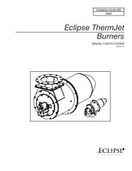
TYPICAL UL SCHEMATIC GAS PIPING<br />
GAS PILOT LINE<br />
D2393<br />
GAS PIPING<br />
• The main gas train must be connected to the gas<br />
attachment 1)(A), using flange 2), gasket 3) and<br />
screws 4) supplied with the burner.<br />
• The gas train can enter the burner from the right or left<br />
side, depending on which is the most convenient, see<br />
fig. (A).<br />
• The gas safety shut-off valves 5)-6)(A) must be as<br />
close as possible to the burner to ensure gas reaches<br />
the combustion head within the safety time range.<br />
• The pilot gas train must be connected to the gas<br />
attachment 5)(A) and can enter the burner from the<br />
right or left side.<br />
GAS TRAIN (B)<br />
It must be type-approved according to required standards<br />
and is supplied separately from the burner.<br />
Note<br />
See the accompanying instructions for the adjustment of<br />
the gas train.<br />
KEY (A)<br />
1 - <strong>Gas</strong> input pipe<br />
2 - Manual valve<br />
3 - Pressure regulator<br />
4 - Low gas pressure switch<br />
5 - 1st safety shut off valve VS<br />
6 - 2nd safety shut off valve VR<br />
7 - Standard issue burner with flange gasket<br />
8 - <strong>Gas</strong> adjustment butterfly valve *<br />
9 - Burner<br />
10 - High gas pressure switch *<br />
* On the burner<br />
(B)<br />
MAIN GAS LINE<br />
D2438<br />
9
LOW GAS PRESSURE SWITCH HIGH GAS PRESSURE SWITCH AIR PRESSURE SWITCH<br />
D2547 D2547 D2548<br />
(A)<br />
(B)<br />
(C)<br />
ADJUSTMENTS BEFORE FI<strong>RS</strong>T FIRING<br />
Adjustment of the combustion head, and air and gas<br />
deliveries has been illustrated on page 8.<br />
In addition, the following adjustments must also be<br />
made:<br />
- Open manual valves up-stream from the gas train.<br />
- Adjust the low gas pressure switch to the start of the<br />
scale (A).<br />
- Adjust the high gas pressure switch to the end of the<br />
scale (B).<br />
- Adjust the air pressure switch to the zero position of<br />
the scale (C).<br />
- Purge the air from the gas line.<br />
Fit a U-type manometer (D) to the gas pressure test<br />
point on the sleeve.<br />
The manometer readings are used to calculate the<br />
MAX. burner power using the table on page 6.<br />
Before starting up the burner it is good practice to adjust<br />
the gas train so that ignition takes place in conditions of<br />
maximum safety, i.e. with gas delivery at the minimum.<br />
(D)<br />
D2401<br />
10
(A)<br />
(B)<br />
D2585<br />
Position jumpers<br />
YES<br />
Figure above shows how the servomotor<br />
is released to manually check<br />
there is no binding though its motion.<br />
D2277<br />
NO<br />
Don’t release the button indicated<br />
in this figure: the syncronization<br />
of the cams<br />
made in factory would be<br />
changed.<br />
Trim potentiometers<br />
Slide switch<br />
SERVOMOTOR<br />
The servomotor gives simultaneous regulation of the air<br />
damper through the variable cam profile 4)(F) and the<br />
gas butterfly valve.<br />
It rotates by 130° in approx. 35 s.<br />
The factory settings must not be changed for the first firing,<br />
just check that they comply with the details below.<br />
To open the servomotor, remove the screws and pull the<br />
cover outward, fig. (A).<br />
CAMS AND TRIM POTENTIOMETE<strong>RS</strong> FUNC-<br />
TIONS<br />
Cam 1: 130°<br />
Limits rotation towards maximum for gas.<br />
Cam 2: 0°<br />
Limits rotation towards minimum, air damper closed on<br />
stand by.<br />
Cam 3: 20°<br />
Limits gas ignition position.<br />
Cams 4 - 5 - 6 - 7 - 8: not used<br />
Trim potentiometer MAX<br />
Limits maximum modulation.<br />
It must be set near the stroke end (cam 1) to exploit as<br />
far as possible the variable profile cam and maximum<br />
opening of the gas butterfly valve.<br />
Trim potentiometer MIN<br />
Limits minimum modulation.<br />
It must be set near the stroke end (cam 2) to exploit as<br />
far as possible the variable profile cam.<br />
Trim potentiometer POS<br />
Limits an intermediate operating position between MAX<br />
and MIN, supplying power to the "P" terminal in the servomotor<br />
(through an external command). This function<br />
cuts out any external signals.<br />
Note<br />
Using the slide switch to select MAX or MIN, the servomotor<br />
goes into the position for the respective settings of<br />
the MAX and MIN TRIM POTENTIOMETE<strong>RS</strong>.<br />
When the settings are complete, place the slide switch<br />
on OPE.<br />
(C)<br />
(D)<br />
(E)<br />
D2593<br />
1 Servomotor<br />
2 Graduated sector for gas<br />
butterfly valve<br />
3 Index for graduated sector 2<br />
4 Adjustable profile cam<br />
5 Adjustment screws for cam<br />
starting profile<br />
6 Adjustment fixing screws<br />
7 Adjustment screws for cam<br />
and profile<br />
(F)<br />
D2594<br />
11
Position jumpers<br />
(A)<br />
(B)<br />
(C)<br />
1 Servomotor<br />
2 Graduated sector for gas butterfly valve<br />
3 Index for graduated sector 2<br />
4 Adjustable profile cam<br />
5 Adjustment screws for cam starting profile<br />
6 Adjustment fixing screws<br />
7 Adjustment screws for cam and profile<br />
Trim potentiometers<br />
Slide switch<br />
D2593<br />
BURNER STARTING<br />
Close the control circuit, with the switch in fig. C) in the<br />
AUTO position.<br />
On firing (pilot burner and main valve) turn the switch (C)<br />
to MAN and the switch 1)(E) in the AUT position.<br />
MAXIMUM OUTPUT<br />
Using button (B), "increase output" until it stops, app.<br />
130° (cam 1).<br />
Place the slide switch on MAX and set the relative MAX<br />
trim potentiometer (setting must be very near to 130°) to<br />
exploit as far as possible the variable profile cam 4)(D)<br />
and have the gas butterfly valve on maximum opening,<br />
graduated sector 2) on index 3) fig. (D).<br />
The setting of the gas flow must be made on the gas train<br />
regulator and, if necessary, on the gas valve.<br />
The air setting must be made on the variable profile cam<br />
4)(D) by turning the screws 5), after loosening the screws<br />
6).<br />
MINIMUM OUTPUT<br />
With the slide switch on the OPE position, use button (B)<br />
"decrease output" until it stops at app. 20° (cam 3).<br />
Put the slide switch in the MIN position and set the modulation<br />
minimum using the relative MIN trim potentiometer.<br />
Set the air using the variable profile cam 4)(D).<br />
If a lower modulation minimum is required than the level<br />
set on cam 3 of the servomotor (20°), decrease the cam<br />
setting.<br />
INTERMEDIATE OUTPUTS<br />
With the switch (C) in the AUTO position, the slide switch<br />
in the OPE position and the switch 1)(E) in the MAN position,<br />
move the button 2)(E) in various intermediate levels<br />
between maximum and minimum and set the variable<br />
profile cam 4)(D) to achieve optimum combustion, by<br />
turning the screws 5).<br />
If possible, do not change the previously set maximum<br />
and minimum levels.<br />
Check the various setting levels with a combustion analysis.<br />
Important<br />
Make a progressive adjustment of the profile, without<br />
sharp changes.<br />
When the setting is complete, lock the cam profile using<br />
screws 6)(D).<br />
Turn the burner off, release the servomotor as shown in<br />
fig. (B) page 11 and manually turn cam 4)(D) to check<br />
there is no binding.<br />
Finally fix the adjustment by turning the screws 6)(D).<br />
(D)<br />
D2594<br />
1 2<br />
(E)<br />
D791<br />
12
AIR PRESSURE SWITCH<br />
AIR PRESSURE SWITCH (A)<br />
Adjust the air pressure switch after having performed all<br />
other burner adjustments with the air pressure switch set<br />
to the start of the scale (A).<br />
With the burner operating at min. output, increase adjustment<br />
pressure by slowly turning the relative dial clockwise<br />
until the burner locks out.<br />
Then turn the dial anti-clockwise by about 20% of the set<br />
point and repeat burner starting to ensure it is correct.<br />
If the burner locks out again, turn the dial anti-clockwise<br />
a little bit more.<br />
Attention:<br />
As a rule, the air pressure switch must prevent the formation<br />
of CO.<br />
To check this, insert a combustion analyser into the<br />
chimney, slowly close the fan suction inlet (for example<br />
with cardboard) and check that the burner locks out,<br />
before the CO in the fumes exceeds 400 ppm.<br />
The air pressure switch may operate in "differential"<br />
operation in two pipe system. If a negative pressure in<br />
the combustion chamber during pre-purging prevents<br />
the air pressure switch from switching, switching may be<br />
obtained by fitting a second pipe between the air pressure<br />
switch and the suction inlet of the fan. In such a<br />
manner the air pressure switch operates as differential<br />
pressure switch.<br />
(A)<br />
HIGH GAS PRESSURE SWITCH<br />
D2548<br />
(B)<br />
LOW GAS PRESSURE SWITCH<br />
D2547<br />
HIGH GAS PRESSURE SWITCH (B)<br />
Adjust the high gas pressure switch after having performed<br />
all other burner adjustments with the maximum<br />
gas pressure switch set to the end of the scale (B).<br />
With the burner operating at MAX output, reduce the<br />
adjustment pressure by slowly turning the adjustment<br />
dial anticlockwise until the burner locks out.<br />
Then turn the dial clockwise by 0.8” WC and repeat<br />
burner firing.<br />
If the burner locks out again, turn the dial again clockwise<br />
by 0.4” WC.<br />
(C)<br />
D2547<br />
DA<br />
LOW GAS PRESSURE SWITCH (C)<br />
Adjust the low gas pressure switch after having performed<br />
all the other burner adjustments with the pressure<br />
switch set at the start of the scale (C).<br />
With the burner operating at MAX output, increase adjustment<br />
pressure by slowly turning the relative dial<br />
clockwise until the burner locks out.<br />
Then turn the dial anti-clockwise by 0.8” WC and repeat<br />
burner starting to ensure it is uniform.<br />
If the burner locks out again, turn the dial anti-clockwise<br />
again by 0.4” WC.<br />
FLAME PRESENT CHECK (D)<br />
The burner is fitted with an ionisation (flame rod) system<br />
which ensures that a flame is present. The minimum<br />
current for reliable operation is 6 µA (see manufacturers<br />
documentation). The burner provides a much higher current,<br />
so that controls are not normally required. However,<br />
if it is necessary to measure the ionisation current,<br />
disconnect the plug-socket 6)(A)p.4 on the ionisation<br />
probe cable and insert a direct current microamperometer<br />
with a base scale of 100 µA. Carefully check polarities.<br />
(D)<br />
D795<br />
13
FLAME INSPECTION WINDOW<br />
(A)<br />
OPENING THE BURNER<br />
D<strong>70</strong>9<br />
MAINTENANCE<br />
Combustion<br />
The optimum calibration of the burner requires an analysis<br />
of the flue gases. Significant differences with respect<br />
to the previous measurements indicate the points where<br />
more care should be exercised during maintenance.<br />
<strong>Gas</strong> leaks<br />
Make sure that there are no gas leaks on the pipework<br />
between the gas meter and the burner.<br />
Flame inspection window<br />
Clean the flame inspection window (A).<br />
Combustion head<br />
Open the burner and make sure that all components of<br />
the combustion head are in good condition, not<br />
deformed by the high temperatures, free of impurities<br />
from the surroundings and correctly positioned. If in<br />
doubt, disassemble the elbow fitting 5)(B).<br />
Servomotor<br />
Disengage the cam 4)(D)p. 12 from the servomotor and<br />
turn it backwards and forwards by hand to make sure it<br />
moves freely.<br />
Burner<br />
Check for excess wear or loose screws in the mechanisms<br />
controlling the air damper and the gas butterfly<br />
valve. Also make sure that the screws securing the electrical<br />
leads in the burner terminal strip are fully tightened.<br />
Clean the outside of the burner, taking special care with<br />
the swivel joints and cam.<br />
Combustion<br />
Adjust the burner if the combustion values found at the<br />
beginning of the operation do not comply with the regulations<br />
in force, or do not correspond to good combustion.<br />
Record the new combustion values; they will be<br />
useful for subsequent controls.<br />
(B)<br />
D2402<br />
TO OPEN THE BURNER (B):<br />
- Switch off the electrical power.<br />
- Loosen screws 1) and withdraw cover 2).<br />
- Disengage the swivel joint 7) from the graduated sector<br />
8).<br />
- Fit the two extensions onto the slide bars 4).<br />
- Remove screws 3), and pull the burner back by about<br />
4” on the slide bars 4). Disconnect the probe and<br />
electrode leads and then pull the burner fully back.<br />
Now extract the gas distributor 5) after having removed<br />
the screw 6) and disconnecting the pilot gas line.<br />
TO CLOSE THE BURNER (B):<br />
- Push the burner until it is about 4” from the sleeve.<br />
- Re-connect the leads and slide in the burner until it<br />
comes to a stop.<br />
- Refit screws 3), and pull the probe and electrode<br />
leads gently out until they are slightly stretched.<br />
- Re-couple the swivel joint 7) to the graduated sector<br />
8).<br />
- Remove the two extensions from the slide bars 4).<br />
- Connect the pilot gas line.<br />
14
Factory Wiring Diagram<br />
<strong>RS</strong> <strong>70</strong>/M - <strong>RS</strong> 100/M - <strong>RS</strong> 130/M<br />
with burner mounted Siemens LFL control<br />
D2332<br />
Continuous fan operation<br />
Change the wire connection from terminal 6 to terminal 1, move the jumper from terminals 12-13 to terminals 4-12 and<br />
remove the wire from terminal 13 of control box as indicated below.<br />
(A)<br />
LAYOUT (A)<br />
Burner <strong>RS</strong> <strong>70</strong>-100-130/M<br />
• Models <strong>RS</strong> <strong>70</strong>-100-130/M leave the factory preset for 208-230 V power supply.<br />
• If 460 V power supply is used, change the motor connection from delta to star and change the setting of the thermal cut-out as well.<br />
Key to Layout (A)<br />
CMV - Motor contactor<br />
DA - LFL Control box<br />
MB - Burner terminal strip<br />
MV - Fan motor<br />
PA - Air pressure switch<br />
PGM - High gas pressure switch<br />
SM - Servomotor<br />
SO - Ionisation probe (flame rod)<br />
SP - Plug-socket<br />
TA - Ignition transformer<br />
TB - Burner ground<br />
15<br />
D2878
Field Wiring Diagram<br />
<strong>RS</strong> <strong>70</strong>-100-130/M<br />
with burner mounted Siemens LFL control<br />
D2333<br />
(A)<br />
208 -<br />
230 V<br />
<strong>RS</strong> <strong>70</strong>/M <strong>RS</strong> 100/M <strong>RS</strong> 130/M<br />
460 V 575 V<br />
208 -<br />
230 V<br />
460 V 575 V<br />
208 -<br />
230 V<br />
460 V 575 V<br />
F A T10 T6 T6 T15 T10 T6 T15 T10 T10<br />
S AWG 14 14 14 14 14 14 14 14 14<br />
(B)<br />
ELECTRICAL CONNECTIONS<br />
Use flexible cables according to local Regulations.<br />
LAYOUT (A)<br />
Electrical connection <strong>RS</strong> <strong>70</strong>-100-130/M burners<br />
Fuses and wire size layout (A), see table (B).<br />
Wire size when not indicated: AWG18.<br />
KEY TO LAYOUT (A)<br />
IN - Burner manual stop switch<br />
MB - Burner terminal strip<br />
PG - Min. gas pressure switch<br />
PS - Remote lock-out reset<br />
H1 - Remote lock-out signal<br />
H2 - Burner on signal<br />
H4 - <strong>Power</strong> on signal<br />
H5 - Permission ok<br />
OC - Operating control<br />
OC2 - High-low control<br />
HL - High limit<br />
VP - Pilot adjustment valve<br />
VPS - Pilot valve (safety)<br />
VR - Adjustment valve<br />
VS - Safety valve<br />
NOTES<br />
• The setting of the thermal overload must be according to the total<br />
burner amperage draw.<br />
• The <strong>RS</strong> <strong>70</strong>-100-130/M burners leave the factory preset for 208-<br />
230 V power supply. If 460 V power supply is used, change the fan<br />
motor connection from delta to star and change the setting of the<br />
thermal overload as well.<br />
• The <strong>RS</strong> <strong>70</strong>-100-130/M burners have been type-approved for intermittent<br />
operation. This means they should compulsorily be<br />
stopped at least once every 24 hours to enable the control box to<br />
check its own efficiency at start-up. Burner halts are normally provided<br />
for automatically by the boiler load control system.<br />
If this is not the case, a time switch should be fitted in series to IN<br />
to provide for burner shut-down at least once every 24 hours.<br />
16
Factory Wiring Diagram<br />
<strong>RS</strong> <strong>70</strong>/M - <strong>RS</strong> 100/M - <strong>RS</strong> 130/M with remote control panel<br />
(A)<br />
D2397<br />
ELECTRICAL SYSTEM<br />
LAYOUT (B)<br />
Burner <strong>RS</strong> <strong>70</strong>-100-130/M<br />
The flame safeguard is in remote panel.<br />
See the internal electrical systems of the remote panel in order to have the complete wiring diagram.<br />
Key to Layout (A)<br />
CMV - Motor contactor<br />
DA - Control box<br />
MB - Burner terminal strip<br />
MV - Fan motor<br />
PA - Air pressure switch<br />
PGM - High gas pressure switch<br />
SM - Servomotor<br />
SO - Ionisation probe (flame rod)<br />
SP - Plug-socket<br />
TA - Ignition transformer<br />
TB - Burner ground<br />
17
APPENDIX - Burner firing rates according to air density<br />
above sea level<br />
average barom.<br />
pressure<br />
CORRECTION FACTOR F<br />
Air temperature<br />
°F (°C)<br />
ft m “ W.C. mbar 0 (0°C) 41 (5°C) 50 (10°C) 59 (15°C) 68 (20°C) 77 (25°C) 86 (30°C) 104 (40°F)<br />
0<br />
329<br />
658<br />
987<br />
1316<br />
1645<br />
1974<br />
2303<br />
2632<br />
2961<br />
3290<br />
3947<br />
4605<br />
5263<br />
5921<br />
6579<br />
0<br />
100<br />
200<br />
300<br />
400<br />
500<br />
600<br />
<strong>70</strong>0<br />
800<br />
900<br />
1000<br />
1200<br />
1400<br />
1600<br />
1800<br />
2000<br />
399<br />
394<br />
389<br />
385<br />
380<br />
376<br />
372<br />
367<br />
363<br />
358<br />
354<br />
346<br />
337<br />
329<br />
321<br />
313<br />
1013<br />
1000<br />
989<br />
978<br />
966<br />
955<br />
944<br />
932<br />
921<br />
910<br />
898<br />
878<br />
856<br />
836<br />
815<br />
794<br />
1,087<br />
1,073<br />
1,061<br />
1,050<br />
1,037<br />
1,025<br />
1,013<br />
1,000<br />
0,988<br />
0,977<br />
0,964<br />
0,942<br />
0,919<br />
0,897<br />
0,875<br />
0,852<br />
1,068<br />
1,054<br />
1,042<br />
1,031<br />
1,018<br />
1,007<br />
0,995<br />
0,982<br />
0,971<br />
0,959<br />
0,946<br />
0,925<br />
0,902<br />
0,881<br />
0,859<br />
0,837<br />
1,049<br />
1,035<br />
1,024<br />
1,013<br />
1,000<br />
0,989<br />
0,977<br />
0,965<br />
0,954<br />
0,942<br />
0,930<br />
0,909<br />
0,886<br />
0,866<br />
0,844<br />
0,822<br />
1,031<br />
1,017<br />
1,006<br />
0,995<br />
0,983<br />
0,972<br />
0,960<br />
0,948<br />
0,937<br />
0,926<br />
0,914<br />
0,893<br />
0,871<br />
0,851<br />
0,829<br />
0,808<br />
1,013<br />
1,000<br />
0,989<br />
0,978<br />
0,966<br />
0,955<br />
0,944<br />
0,932<br />
0,921<br />
0,910<br />
0,898<br />
0,878<br />
0,856<br />
0,836<br />
0,815<br />
0,794<br />
0,996<br />
0,983<br />
0,972<br />
0,962<br />
0,950<br />
0,939<br />
0,928<br />
0,916<br />
0,906<br />
0,895<br />
0,883<br />
0,863<br />
0,842<br />
0,822<br />
0,801<br />
0,781<br />
0,980<br />
0,967<br />
0,956<br />
0,946<br />
0,934<br />
0,923<br />
0,913<br />
0,901<br />
0,891<br />
0,880<br />
0,868<br />
0,849<br />
0,828<br />
0,808<br />
0,788<br />
0,768<br />
0,948<br />
0,936<br />
0,926<br />
0,916<br />
0,904<br />
0,894<br />
0,884<br />
0,872<br />
0,862<br />
0,852<br />
0,841<br />
0,822<br />
0,801<br />
0,783<br />
0,763<br />
0,743<br />
(A)<br />
The FIRING RATE area values have been obtained considering a surrounding<br />
temperature of 68°F (20°C), and an atmospheric pressure of 398” W.C.<br />
and with the combustion head adjusted as shown on page 8.<br />
The burner may be required to operate with combustion air at a higher temperature<br />
and/or at higher altitudes.<br />
Heating of air and increase in altitude produce the same effect: the expansion<br />
of the air volume, i.e. the reduction of air density.<br />
The burner fan's delivery remains substantially the same, but the oxygen<br />
content per cubic meter and the fan's head are reduced.<br />
It is therefore important to know if the maximum output required of the burner<br />
at a given combustion chamber pressure remains within the burner's firing rate range even at different temperature and altitude conditions.<br />
Proceed as follows to check the above:<br />
“ W.C.<br />
1 -Find the correction factor F in the Table (A) for the plant's air temperature and altitude.<br />
2 -Divide the burner's delivery Q by F in order to obtain the equivalent delivery Qe:<br />
H2<br />
H3<br />
H1<br />
D2617<br />
Qe<br />
A<br />
MBTU/h<br />
(B)<br />
Qe = Q : F<br />
(MBtu/hr)<br />
3 -In the firing rate range of the burner, Fig. (B), indicate the work point defined by:<br />
Qe = equivalent delivery<br />
H1 = combustion chamber pressure<br />
The resulting point A must remain within the firing rate range.<br />
4 -Plot a vertical line from Point A as shown in Figure (B) and find the maximum pressure H2 of the firing rate.<br />
5 -Multiply H2 by F to obtain the maximum reduced pressure H3 of the firing rate.<br />
H3 = H2 x F<br />
(“ W.C.)<br />
If H3 is greater than H1, as shown in Fig. (B), the burner delivers the output required.<br />
If H3 is lower than H1, the burner's delivery must be reduced. A reduction in delivery is accompanied by a reduction of the pressure in<br />
the combustion chamber:<br />
Qr = reduced delivery<br />
H1r = reduced pressure<br />
H1r = H1 x (<br />
Qr<br />
)<br />
2<br />
Q<br />
Example, a 5% delivery reduction:<br />
Qr = Q x 0.95<br />
H1r = H1 x (0.95) 2<br />
Steps 2 - 5 must now be repeated using the new Qr and H1r values.<br />
Important: the combustion head must be adjusted in respect to the equivalent delivery Qe.<br />
18
Full Modulation<br />
BURNER OPERATION<br />
BURNER STARTING<br />
• Load control close.<br />
Fan motor starts.<br />
• Servomotor starts:<br />
130° rotation to right, until contact is made on cam<br />
1)(A) page 12.<br />
The air damper is positioned to MAX. output.<br />
• Pre-purge stage with air delivery at MAX. output.<br />
• After pre-purge stage, servomotor rotates to left up to<br />
the angle set on cam 3)(A) page 12 for MIN. output.<br />
• The air damper and the gas butterfly are positioned to<br />
MIN. output.<br />
• Ignition electrode strikes a spark.<br />
• Pilot valve opens. The pilot flame is ignited.<br />
• After about 12 s the main flame ignites and starting<br />
cycle ends.<br />
(A)<br />
Low - High<br />
D2273<br />
STEADY STATE OPERATION<br />
At the end of the starting cycle, the servomotor control<br />
then passes to the load control for boiler pressure or<br />
temperature.<br />
(The LFL control box continues, however, to check that<br />
the flame is present and that the air pressure switch is in<br />
the correct position.)<br />
• If the temperature or pressure is low, the burner progressively<br />
increases its output to the MAX. value.<br />
• If the temperature or pressure is high, the burner progressively<br />
decreases its output to the MIN. value.<br />
And so on.<br />
• The burner locks out when demand for heat is less<br />
than the heat supplied by the burner at min. output.<br />
Load control opens. The servomotor returns to the 0°<br />
angle limited by contact with cam 2. The air damper<br />
closes completely to reduce thermal dispersion to a<br />
minimum.<br />
Every time output is changed, the servomotor automatically<br />
modifies gas delivery (gas butterfly valve) and air<br />
delivery (fan air damper).<br />
Switching times are given in seconds, in the burner startup<br />
sequence.<br />
LFL 1.335 Series 01<br />
t1<br />
t2<br />
t3<br />
t4<br />
t5<br />
30<br />
2<br />
4<br />
20<br />
optional<br />
t6<br />
t7<br />
t8<br />
t9<br />
optional<br />
12<br />
4<br />
16<br />
(B)<br />
D2274<br />
Legend for the times<br />
t1 Pre-purge time with air damper open<br />
t2 Safety time<br />
t3 Pre-ignition time, short (ignition transformer on<br />
terminal 16)<br />
t4 Interval between start of t2 and release of valve<br />
at terminal 19<br />
t5 Interval between end of t4 and release of load<br />
controller or valve at terminal 20<br />
t5 Running time of air damper into OPEN position<br />
t6 Running time of air damper into low-flame position<br />
(MIN)<br />
t7 Permissible after-burn time<br />
t8 Interval until OPEN command for the air damper<br />
is given<br />
t9 Running time of pilot<br />
FIRING FAILURE<br />
If the burner does not fire, it locks out within 2.5 seconds<br />
from opening the pilot valve and then within 5 seconds<br />
from opening the main valves.<br />
BURNER FLAME GOES OUT DURING OPERATION<br />
If the flame should accidentally go out during operation,<br />
the burner will lock out within 1s.<br />
19
BURNER FAULTS<br />
Control program under fault<br />
conditions and lock-out<br />
indication<br />
In case of any disturbance, the sequence mechanism stops and with it the lock-out indicator. The symbol<br />
above the reading mark of the indicator gives the type of disturbance:<br />
No start, e.g. because one contact is not closed. Lock-out during or after control program sequence<br />
due to extraneous light (e.g. non-extinguished flames, leaking fuel valves, defects in the flame<br />
supervision circuit, etc.)<br />
Interruption of startup sequence, because the OPEN signal has not been delivered to terminal 8<br />
by limit switch “a”. Terminals 6, 7 and 14 remain under voltage until the fault has been corrected!<br />
P<br />
Lockout, because there is no air pressure indication at the beginning of air pressure control.<br />
Every air pressure failure after this moment in time leads to lock-out, too!<br />
Lock-out due to a fault in the flame supervision circuit.<br />
Interruption of startup sequence, because the position signal for the low-flame position has not<br />
been delivered to terminal 8 by auxiliary switch “m”. Terminals 6, 7 and 14 remain under voltage until<br />
the fault has been corrected!<br />
1<br />
Lock-out, because no flame signal is present after completion of the (1st) safety time.<br />
2<br />
Lock-out, because no flame signal has been received on completion of the 2nd safety time (flame<br />
signal of the main flame with interrupted pilot burners).<br />
Lock-out, because the flame signal has been lost during burner operation.<br />
If lock-out occurs at any other moment in time between the start and the pre-ignition wich is not marked by a<br />
symbol, this is usually caused by a premature, i.e. faulty flame signal, e.g. caused by a self-igniting UV tube.<br />
20
BURNER START UP REPORT<br />
Model number:<br />
Project name:<br />
Installing contractor:<br />
Serial number:<br />
Start-up date:<br />
Phone number:<br />
GAS OPERATION<br />
<strong>Gas</strong> Supply Pressure:<br />
Main <strong>Power</strong> Supply:<br />
Control <strong>Power</strong> Supply:<br />
Burner Firing Rate:<br />
Manifold Pressure:<br />
Pilot Flame Signal:<br />
Low Fire Flame Signal:<br />
High Fire Flame Signal:<br />
CO 2 : Low Fire<br />
O 2 : Low Fire<br />
CO: Low Fire<br />
NO X : Low Fire<br />
Net Stack Temp - Low Fire:<br />
Comb. Efficiency - Low Fire:<br />
Overfire Draft:<br />
High Fire<br />
High Fire<br />
High Fire<br />
High Fire<br />
High Fire:<br />
High Fire:<br />
OIL OPERATION<br />
Oil supply pressure:<br />
Oil suction pressure:<br />
Control <strong>Power</strong> Supply:<br />
Burner Firing Rate:<br />
Low Fire Flame Signal:<br />
High Fire Flame Signal:<br />
Low Fire Nozzle Size:<br />
High Fire Nozzle Size:<br />
CO 2 : Low Fire<br />
O 2 : Low Fire<br />
CO: Low Fire<br />
NO X : Low Fire<br />
Net Stack Temp - Low Fire:<br />
Comb. Efficiency - Low Fire:<br />
Overfire Draft:<br />
Smoke number:<br />
High Fire<br />
High Fire<br />
High Fire<br />
High Fire<br />
High Fire:<br />
High Fire:<br />
CONTROL SETTINGS<br />
Operating Setpoint:<br />
High Limit Setpoint:<br />
Low <strong>Gas</strong> Pressure:<br />
High <strong>Gas</strong> Pressure:<br />
Low Oil Pressure:<br />
High Oil Pressure:<br />
Flame Safeguard Model Number:<br />
Modulating Signal Type:<br />
NOTES<br />
21
Represented By:<br />
<strong>Power</strong> <strong>Equipment</strong> <strong>Company</strong><br />
2011 Williamsburg Road<br />
Richmond, VA 23231<br />
Ph: 804-236-3800<br />
Fx: 804-236-3882<br />
www.peconet.com