LeCroy XMC Gen2 Interposer Datasheet - Teledyne LeCroy
LeCroy XMC Gen2 Interposer Datasheet - Teledyne LeCroy
LeCroy XMC Gen2 Interposer Datasheet - Teledyne LeCroy

You also want an ePaper? Increase the reach of your titles
YUMPU automatically turns print PDFs into web optimized ePapers that Google loves.
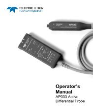
<strong>Gen2</strong> <strong>XMC</strong> <strong>Interposer</strong> Card<br />
for PCI Express ®<br />
Protocol Solutions Group<br />
Product <strong>Datasheet</strong><br />
t<br />
<strong>XMC</strong> <strong>Interposer</strong> Card Enables Probing of<br />
PCI Express Traffic with Quick, Simple Setup!<br />
Specifications<br />
Dimensions<br />
Lane Width<br />
Data Rate<br />
34.3 x 7.4 cm<br />
(13.5” x 2.9”)<br />
x1, x2, x4, or x8<br />
2.5 GT/s (Gen1) and<br />
5 GT/s (<strong>Gen2</strong>)<br />
Compatibility VITA 42.3 compliant<br />
modules<br />
Ordering Information<br />
PE048UIA-X <strong>XMC</strong> <strong>Gen2</strong> x8 <strong>Interposer</strong><br />
Card for Summit T2-16<br />
and Summit T3-16<br />
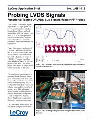
The <strong>LeCroy</strong> <strong>Gen2</strong> <strong>XMC</strong> <strong>Interposer</strong> Card allows users to connect a <strong>LeCroy</strong><br />
PCI Express Analyzer between a VITA 42.3 (<strong>XMC</strong>) mezzanine module and<br />
the carrier board. The analyzer can be used to capture, decode and display<br />
all traffic on the PCI Express bus for troubleshooting, debugging and<br />
monitoring system performance.<br />
Installation is quick and simple: The interposer card is plugged into the<br />
card slot in place of the <strong>XMC</strong> module, the <strong>XMC</strong> module is plugged into the<br />
interposer, and the analyzer is connected to a separate connector on the<br />
interposer card.<br />
The <strong>XMC</strong> <strong>Interposer</strong> Card supports PCI Express lane widths up to x8 at<br />
data rates of 2.5<br />
GT/s and 5 GT/s. The card supports an analyzer<br />
connection to <strong>LeCroy</strong> Summit T28, T2-16, T3-8 or T3-16 Analyzers.<br />
<strong>XMC</strong> (VITA 42) expands the existing PMC standard by adding switched<br />
fabric interconnects and adds new connectors (Pn5 and Pn6) that are<br />
specifically chos<br />
sen to support high-speed differential signals for fabrics or<br />
user I/O.<br />
<strong>LeCroy</strong> is a strong supporter of embedded board communication and<br />
provides advanced tools for rapid product development and debugging of<br />
new <strong>XMC</strong> products.<br />
7.4 cm<br />
(2.9”)
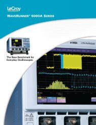
<strong>XMC</strong> <strong>Interposer</strong> Interconnection Overview<br />
<strong>XMC</strong> Device<br />
Under Test<br />
DUT Connection<br />
On Back Side<br />
SW1: Lane Width DIP<br />
Switches<br />
PCIe<br />
Lanes<br />
SW_1 SW-2 SW-3<br />
x1 ON ON ON<br />
x2 OFF ON<br />
x4 OFF OFF<br />
ON<br />
ON<br />
x8 OFF OFF<br />
OFF<br />
CONFIG ROM: On = Write Free;<br />
SW-4<br />
Off = Write Protection (Default)<br />
SW2: Clock DIP Switches<br />
iPASS Cable<br />
SW-1 SW-2 SW-3 SW-4<br />
Upstream Downstream<br />
Slot_CLK Slot_CLK ON ON ON ON<br />
US_CLK US_CLK OFF ON OFF ON<br />
DS_CLK DS_CLK ON OFF ON OFF<br />
US_CLK DS_CLK OFF ON ON OFF<br />
Note: The DUT always uses the Slot_CLK<br />
<strong>XMC</strong> <strong>Interposer</strong><br />
<strong>XMC</strong><br />
Slot<br />
Link Status LEDs<br />
DS Ref Clk IN<br />
US Ref Clk IN<br />
Summit T28 Analyzer<br />
12V DC IN<br />
(from adapter supplied)<br />
Connecting the <strong>XMC</strong> <strong>Interposer</strong><br />
1. Set the DIP switches on the <strong>XMC</strong> <strong>Interposer</strong> to the correct<br />
setting for the lane width desired (x1, x2, x4 or x8) and for the<br />
desired Ref Clock Inputs (if used).<br />
2. Install the <strong>XMC</strong> <strong>Interposer</strong> into the <strong>XMC</strong> Backplane or Slot.<br />
3. Install the <strong>XMC</strong> Device Under Test (DUT) into the <strong>XMC</strong><br />
<strong>Interposer</strong> (on backside).<br />
4. Connect 12V DC using the AC adapter supplied with the<br />
interposer. Make sure that the adapter is turned on.<br />
5. Connect the Summit T28 Analyzer (or other <strong>LeCroy</strong> PCI<br />
Express analyzer) to the <strong>XMC</strong> <strong>Interposer</strong>.<br />
6. Connect the analyzer to a host computer system using the<br />
USB 2.0 port on the rear panel of the Summit T28 analyzer.<br />
7. Install the software on the host system.<br />
8. Power on the analyzer.<br />
9. Power on the <strong>XMC</strong> system.<br />
10. Use the <strong>LeCroy</strong> software application to monitor, record and<br />
view PCI Express traffic in the <strong>XMC</strong> system.<br />
System Compatibility<br />
Summit T28 <br />
Summit T3-8 <br />
Summit T3-16 <br />
Summit T2-16 <br />
1-800-5-<strong>LeCroy</strong><br />
www.lecroy.com<br />
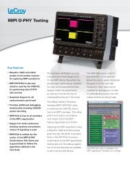
Y-Cable<br />
Connection to<br />
Analyzer<br />
Local sales offices are located throughout the world.<br />
Visit our website to find the most convenient location.<br />
©2011 by <strong>LeCroy</strong> Corporation. All rights reserved. Specifications, prices, availability and delivery subject to change without notice.<br />
Product brand names and logos are trademarks or requested trademarks of their respective holders.<br />
Test<br />
Point<br />
Signal<br />
<strong>XMC</strong> <strong>Gen2</strong> x8 <strong>Interposer</strong> Test Points<br />
Description<br />
TP1 WAKE# Reactivate the links main power rails and reference clocks<br />
TP2 ROOT0# This signal shall be driven low by the carrier to enable the root complex features of a processor <strong>XMC</strong><br />
TP3 TRST# JTAG reset<br />
TP4 MRSTI# <strong>XMC</strong> reset in<br />
TP5 TCK JTAG Clock<br />
TP6 MRSTO# <strong>XMC</strong> reset out<br />
TP7 TMS JTAG mode select<br />
TP8 TDI JTAG data in<br />
TP9 TDO JTAG data out<br />
TP10 GA0 I2C channel select bit 0<br />
TP11 MBIST# <strong>XMC</strong> built-in self test<br />
TP12 GA1 I2C channel select bit 1<br />
TP13 MPRSNT# Module present. This signal allows the carrier to determine whether an <strong>XMC</strong> is present.<br />
TP14 GA2 I2C channel select bit 2.<br />
TP15 MSDA IPMI I2C serial data. This signal shall provide a data line for a two-wire serial management bus.<br />
TP16 MVMRO <strong>XMC</strong> Write Prohibit<br />
TP17 MSCL IPMI I2C serial clock. This signal shall provide a clock reference for a two-wire serial management bus.<br />
TP18 TP_CLKOUT2N Test point of PCIe reference clock (REFCLKN)<br />
TP19 TP_CLKOUT2N Test point of PCIe reference clock (REFCLKP)<br />
TP24 INH# This is an input signal to turn on/off all power to interposer (ground to turn off power)<br />
TP25 VDD+12V_B +12V power supply from host to device (after current sensor)<br />
TP26 VDD+12V +12V power supply from host to device to measure current (current = V from TP26 to TP25 / 0.02)<br />
TP27 VDD-12V_B -12V power supply from host to device (after current sensor)<br />
TP28 VDD-12V -12V power supply from host to device to measure current (current = V from TP28 to TP27 / 0.02)<br />
TP29 VDD5V_B +5V power supply from host to device (after current sensor)<br />
TP30 VDD5V +5V power supply from host to device to measure current (current = V from TP30 to TP29 / 0.02) 02)<br />
TP31 VDD3.3V_B +3.3V power supply from host to device (after current sensor)<br />
TP32 VDD3.3V +3.3V power supply from host to device to measure current (current = V from TP32 to TP31 / 0.02)<br />
TP35 P3P3VRX 3.3V power for interposer – it is the output of regulator U8<br />
TP36 P3P3VTX 3.3V power for interposer – it is the output of regulator U7<br />
TP38 P12V +12V external power supply for interposer<br />
TP39 P2P5V 2.5V power for interposer – it is the output of regulator U9<br />
TP43 3AUX_B 3.3AUX power supply from host to device (after current sensor)<br />
TP44 3AUX 3.3AUX power supply from host to device to measure current (current = V from TP44 to TP43 / 0.02)<br />
TP45 VIO_B VIO power supply from host to device (after current sensor)<br />
TP46 VIO VIO power supply from host to device to measure current (current = V from TP46 to TP35 / 0.01)<br />
TP50 VPWR VPWR power supply from host to device to measure current (current = V from TP50 to TP51 / 0.01)<br />
TP51 VPWR_B VPWR power supply from host to device (after current sensor)<br />
Ground Test Points are available at TP33, TP34, TP37, TP40 and TP47<br />
TP20, TP21, TP23, TP41,TP42, TP48, TP49, TP52, TP53, TP54, TP55 are reserved for future use<br />
PSGGEN2<strong>XMC</strong>DS<br />
04/11