A novel star-ring protection architecture scheme for WDM passive ...
A novel star-ring protection architecture scheme for WDM passive ...
A novel star-ring protection architecture scheme for WDM passive ...

Create successful ePaper yourself
Turn your PDF publications into a flip-book with our unique Google optimized e-Paper software.
JWA53<br />
A <strong>novel</strong> <strong>star</strong>-<strong>ring</strong> <strong>protection</strong> <strong>architecture</strong> <strong>scheme</strong> <strong>for</strong><br />
<strong>WDM</strong> <strong>passive</strong> optical access networks<br />
Xiaofeng SUN, Zhaoxin WANG, Chun-Kit CHAN, and Lian-Kuan CHEN<br />
Department of In<strong>for</strong>mation Enginee<strong>ring</strong>, The Chinese University of Hong Kong, Shatin, HONG KONG SAR.<br />
Tel: +852-2609-8479, Fax: + 852-2603-5032, Email:xfsun3@ie.cuhk.edu.hk<br />
Abstract: We propose and demonstrate a <strong>star</strong>-<strong>ring</strong> network <strong>architecture</strong> and wavelength<br />
assignment <strong>scheme</strong> <strong>for</strong> multi-wavelength <strong>passive</strong> optical networks with full path <strong>protection</strong><br />
capability. Bi-directional traffic can be restored promptly <strong>for</strong> single/multiple link failure scenarios.<br />
© 2004 Optical Society of America<br />
OCIS codes: (060.2330) Fiber optics Communications, (060.4250) Networks<br />
1. Introduction<br />
Broadband networking technologies such as multi-wavelength <strong>passive</strong> optical networks (<strong>WDM</strong>-PONs) [1] have<br />
been extensively studied throughout the past decade <strong>for</strong> last mile applications. Thus, a reliable access network<br />
<strong>architecture</strong> is highly desirable. However, little work has been done to offer the <strong>protection</strong> capability in the optical<br />
access networks. Recently, we have proposed a <strong>WDM</strong>-PON network <strong>architecture</strong> [2] to provide <strong>protection</strong> against<br />
fiber link failure between the remote node (RN) and the optical network units (ONUs), thus the optical line terminal<br />
(OLT) is transparent to such fiber failure. In this paper, we propose and investigate a new network <strong>architecture</strong>,<br />
called <strong>star</strong>-<strong>ring</strong> <strong>protection</strong> <strong>architecture</strong> (SRPA), so as to integrate and extend the capability to protect against link<br />
failure between the RN and the ONUs, as well as that between the RN and the OLT simultaneously. The design and<br />
the <strong>protection</strong> strategies under various failure scenarios will be discussed.<br />
2. Network Topology of SRPA and Wavelength Assignment<br />
Red Band Wavelength<br />
Blue Band Wavelength<br />
OLT<br />
RN<br />
1 2<br />
2xN AWG<br />
F 1 F 2<br />
ONU 6<br />
Optical Line Terminal<br />
2.5Gb/s Data Signal<br />
..<br />
..<br />
1 2 N<br />
1xN A W G<br />
Blue Band Wavelength Red Band Wavelength<br />
FSR<br />
FSR<br />
(D) (U) (D) (U) (D) (U) (D) (U) (U) (D) (U) (D) (U) (D) (U) (D)<br />
L 1<br />
L 5<br />
ONU 7<br />
ONU 8 P 7,8<br />
P 6,7<br />
P 8,1<br />
P 5,6<br />
ONU 1<br />
ONU 5<br />
P 1,2<br />
ONU 2<br />
ONU 3<br />
ONU 4 P 4,5<br />
P 2,3 P 3,4<br />
1 2 3 4 5 6 7 8 9 10 11 12 13 14 15 16<br />
ONU 1 2 3 4 5 6 7 8<br />
D 1 10 3 12 5 14 7 16<br />
U 9 2 11 4 13 6 15 8<br />
*Note: D – Downstream wavelength; U – Upstream wavelength<br />
*The downstream wavelength <strong>for</strong> each ONU is marked with the dot box.<br />
(a)<br />
(b)<br />
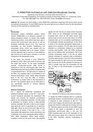
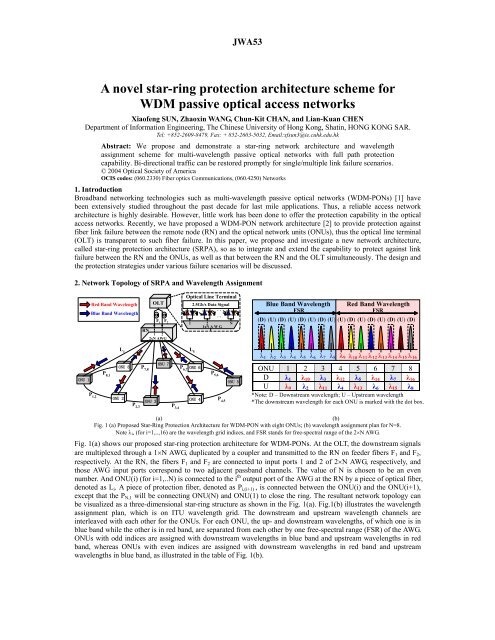
Fig. 1 (a) Proposed Star-Ring Protection Architecture <strong>for</strong> <strong>WDM</strong>-PON with eight ONUs; (b) wavelength assignment plan <strong>for</strong> N=8.<br />
Note i, (<strong>for</strong> i=1,..,16) are the wavelength grid indices, and FSR stands <strong>for</strong> free-spectral range of the 2N AWG.<br />
Fig. 1(a) shows our proposed <strong>star</strong>-<strong>ring</strong> <strong>protection</strong> <strong>architecture</strong> <strong>for</strong> <strong>WDM</strong>-PONs. At the OLT, the downstream signals<br />
are multiplexed through a 1N AWG, duplicated by a coupler and transmitted to the RN on feeder fibers F 1 and F 2 ,<br />
respectively. At the RN, the fibers F 1 and F 2 are connected to input ports 1 and 2 of 2N AWG, respectively, and<br />
those AWG input ports correspond to two adjacent passband channels. The value of N is chosen to be an even<br />
number. And ONU(i) (<strong>for</strong> i=1,..N) is connected to the i th output port of the AWG at the RN by a piece of optical fiber,<br />
denoted as L i . A piece of <strong>protection</strong> fiber, denoted as P i,(i+1) , is connected between the ONU(i) and the ONU(i+1),<br />
except that the P N,1 will be connecting ONU(N) and ONU(1) to close the <strong>ring</strong>. The resultant network topology can<br />
be visualized as a three-dimensional <strong>star</strong>-<strong>ring</strong> structure as shown in the Fig. 1(a). Fig.1(b) illustrates the wavelength<br />
assignment plan, which is on ITU wavelength grid. The downstream and upstream wavelength channels are<br />
interleaved with each other <strong>for</strong> the ONUs. For each ONU, the up- and downstream wavelengths, of which one is in<br />
blue band while the other is in red band, are separated from each other by one free-spectral range (FSR) of the AWG.<br />
ONUs with odd indices are assigned with downstream wavelengths in blue band and upstream wavelengths in red<br />
band, whereas ONUs with even indices are assigned with downstream wavelengths in red band and upstream<br />
wavelengths in blue band, as illustrated in the table of Fig. 1(b).
JWA53<br />
3. Structure of ONU and Protection Mechanism against Fiber Link Failures<br />
Fig. 2(a) illustrates the structure of ONUs under normal operation. The downstream wavelengths i (<strong>for</strong> i is odd) and<br />
i+N (<strong>for</strong> i is even), destined <strong>for</strong> the ONU(i)s are carried via fiber F 1 , AWG and fiber L i . Due to the presence of the<br />
additional fiber feeder F 2 and the channel-shifting input-output property of the AWG, the same <strong>WDM</strong> downstream<br />
signal is also delivered to the respective adjacent ONU(i-1)s, denoted with brackets in Fig. 2. Thus, with the wraparound<br />
spectral periodicity property of the AWG, at any particular ONU(k), two downstream wavelengths, { k ,<br />
k+N+1 ; <strong>for</strong> k is odd} or { k+N , k+1 ; <strong>for</strong> k is even}, of which the <strong>for</strong>mer wavelength is designated <strong>for</strong> ONU(k) in<br />
normal operation; while the latter one is a duplicated copy of the downstream wavelength destined <strong>for</strong> ONU(k+1)<br />
and this serves <strong>for</strong> protecting ONU(k+1), can be received. Similarly, the respective upstream wavelengths { k+N , k+1 ;<br />
<strong>for</strong> k is odd} or { k , k+N+1 ; <strong>for</strong> k is even} can be supported <strong>for</strong> normal operation and <strong>protection</strong> purpose. The<br />
adjacent ONUs are connected by a piece of <strong>protection</strong> fiber in a <strong>ring</strong> <strong>for</strong>m. At the front-end of each ONU, an optical<br />
coupler is used to duplicate the downstream signals, of which one set is destined to itself and the other set is routed<br />
to its adjacent connected ONU <strong>for</strong> <strong>protection</strong> purpose. A 1x2 optical switch is incorporated in each ONU to select<br />
the wavelength signals from the appropriate side. Under normal operation, the switch is configured to the upper port<br />
and selects the downstream signals from the RN. A Red/Blue (R/B) filter is further used to separate the upstream and<br />
the downstream wavelength channels; and also route the <strong>protection</strong> downstream wavelength towards the laser<br />
transmitter (LD) where it will be blocked by the internal isolator of the LD.<br />
OLT<br />
F 1 F 2<br />
1, 10, 3 , ..., 16 1, 10, 3 , ..., 16<br />
9, 2 , 11, ..., 8<br />
ONU 7<br />
ONU 6 ONU 5<br />
ONU 4<br />
OLT<br />
F 1 F 2<br />
1, 10, 3 , ..., 16 1, 10, 3 , ..., 16<br />
9, 11, ..., 8<br />
2<br />
ONU 7<br />
ONU 6 ONU 5<br />
ONU 4<br />
ONU 8<br />
8<br />
RN<br />
(1) 16<br />
9 1<br />
(10)<br />
11<br />
10<br />
2 (3)<br />
3 (12)<br />
ONU 3<br />
ONU 8<br />
8<br />
RN<br />
(1) 16<br />
9 1<br />
2<br />
10<br />
3 (12)<br />
11 ONU 3<br />
Fiber-cut<br />
ONU 1 ONU 2<br />
ONU 1 ONU 2<br />
2<br />
1( 10) 9<br />
10( 3) 2<br />
110<br />
92<br />
Fiber-cut<br />
From<br />
ONU8<br />
1( 10)<br />
OC<br />
9<br />
1( 10)<br />
M<br />
R/B Filter<br />
1<br />
B R<br />
9<br />
PD LD<br />
10( 3)<br />
OC<br />
2 M<br />
R/B Filter<br />
10<br />
R B<br />
2<br />
PD LD<br />
To<br />
ONU3<br />
From<br />
ONU8<br />
110<br />
OC<br />
110<br />
9 M<br />
R/B Filter<br />
110<br />
OC<br />
2 R/B Filter<br />
1<br />
B R<br />
9<br />
10<br />
R B<br />
2<br />
PD LD<br />
PD LD<br />
M<br />
To<br />
ONU3<br />
ONU 1 ONU 2<br />
ONU 1 ONU 2<br />
(a)<br />
(b)<br />
Fig 2. ONU configuration under (a) normal operation; (b) single Type I failure. OC: optical coupler; M: monito<strong>ring</strong> unit<br />
There are two types of fiber failures: Type I (link failure(s) between ONU and RN) and Type II (feeder fiber failure<br />
between OLT and RN). Fig. 2(b) illustrates the ONUs configuration under single Type I failure between the RN and<br />
the ONU(2), <strong>for</strong> instance. A drastic drop in power at the monito<strong>ring</strong> unit (M) of ONU(2) will be detected. Thus, the<br />
optical switch inside ONU(2) will be automatically reconfigured to the lower port, as illustrated in Fig. 2(b). Both<br />
the up-/downstream wavelengths of the isolated ONU(2) will be routed to/from the ONU (1) via the <strong>protection</strong> fiber<br />
between them. Thus, with the channel-shifting property of the AWG at the RN, they can still be routed to the OLT<br />
via the feeder fiber F 2 , as shown in Fig. 2(b). With this <strong>protection</strong> mechanism, a fast restoration of fiber failure can<br />
be achieved, without any disturbance on the existing traffic and other ONUs. If there exists multiple Type I link<br />
failures, the SRPA can still be able to protect and restore the affected traffic using the above mentioned mechanism,<br />
provided that such multiple Type I link failures do not occur at two adjacent ONUs. On the other hand, <strong>for</strong> Type II<br />
fiber feeder failure, <strong>for</strong> example, the fiber feeder F 1 is broken between the RN and the OLT, the <strong>protection</strong><br />
mechanism is similar to that in Type I except that the monito<strong>ring</strong> units in all ONUs will trigger the respective optical<br />
switches simultaneously. The wavelength channels <strong>for</strong> each ONU will be routed via its adjacent ONU and all<br />
wavelengths from all the ONUs will be routed back to the OLT via the fiber feeder F 2 , as illustrated in Fig. 3(b).
JWA53<br />
1<br />
10<br />
3<br />
12<br />
14<br />
7<br />
9<br />
3 11<br />
12<br />
14 6 ONU 7<br />
F 1 7<br />
Fiber-cut<br />
OLT<br />
F 1 2<br />
10 2 ONU 8<br />
4<br />
15<br />
15<br />
ONU 6 ONU 5<br />
15<br />
7<br />
6<br />
14<br />
9<br />
1<br />
2<br />
10<br />
ONU 1<br />
RN<br />
2<br />
Fiber-cut<br />
3<br />
11 4<br />
ONU 2<br />
12<br />
Fiber-cut<br />
ONU 4<br />
ONU 3<br />
4<br />
OLT<br />
F 1<br />
Fiber<br />
cut<br />
3<br />
12<br />
5<br />
14<br />
7<br />
16<br />
8<br />
F 1 9 2<br />
10 2<br />
11<br />
4<br />
13<br />
6<br />
15<br />
8<br />
15<br />
ONU 7<br />
ONU 8<br />
9<br />
ONU 6 ONU 5<br />
15<br />
7<br />
8<br />
16<br />
9<br />
1<br />
2 10<br />
ONU 1<br />
(a)<br />
(b)<br />
Fig. 3. (a) Multiple Type I failure <strong>protection</strong>; (b) Type II feeder fiber, F 1 , failure <strong>protection</strong><br />
6<br />
RN<br />
2<br />
14<br />
6<br />
5<br />
11 34<br />
4. Experimental Demonstration<br />
The transmission per<strong>for</strong>mance and the <strong>protection</strong> switching of our proposed network were experimentally<br />
investigated, using the setup similar to Fig. 2. Two ONUs have been implemented to demonstrate the operation<br />
principle. 2.5-Gb/s directly modulated DFB laser diodes were used at the OLT and the ONUs. A 1616 AWG, with<br />
100-GHz channel spacing and a free-spectral range (FSR) of 12.8nm, was used at the RN. It was also connected to<br />
the 116 AWG, as the channel multiplexer, at the OLT via a pair of 22-km standard single-mode fibers (SMF), as<br />
the fiber feeders. The Red/Blue filters used at the ONUs had 18-nm passband at both red and blue bands. A piece of<br />
4-km <strong>protection</strong> fiber was used to connect the two ONUs. Each ONU was incorporated with one 12 optical switch<br />
to re-route the wavelength under the <strong>protection</strong> mode. Under this configuration, the optical power of the downstream<br />
and upstream signals from the OLT to the ONU(2) was monitored. Both single Type I and Type II fiber link failures<br />
were simulated by intentionally disconnect the fiber connections. The bit-error-rate (BER) per<strong>for</strong>mance under both<br />
the normal and the <strong>protection</strong> path were measured and was depicted in Fig. 4. In all cases, the measured receiver<br />
sensitivities at BER=10-9 were very close to each other. The small induced power penalty (< 0.5dB) compared to<br />
the back-to-back measurement was due to chromatic dispersion of the directly modulated wavelength channels.<br />
BER<br />
13<br />
12<br />
ONU 2<br />
13<br />
ONU 4<br />
ONU 3<br />
11<br />
4<br />
10 -4 Received Power (dBm)<br />
10 -5<br />
10 -6<br />
10 -7 Back to back<br />
Normal Downstream<br />
10 -8 Protection Downstream<br />
Normal Upstream<br />
10 -9 Protection Upsteam<br />
10 -10<br />
-25 -24 -23 -22 -21 -20<br />
Fig. 4 BER measurement of the downstream wavelengths <strong>for</strong> both the normal and the <strong>protection</strong> modes.<br />
Inset shows the switching time measurement under the <strong>protection</strong> mode.<br />
The switching time or the restoration time in case of the simulated fiber cut was also monitored. The result was<br />
shown in the inset of Fig. 4. The wave<strong>for</strong>m showed the signal measured at the monito<strong>ring</strong> unit in ONU(2). The<br />
switching time was measured to be about 9 ms and this corresponded to the network traffic restoration time achieved.<br />
5. Summary<br />
We have proposed a <strong>novel</strong> <strong>star</strong>-<strong>ring</strong> <strong>protection</strong> <strong>architecture</strong> (SRPA) <strong>for</strong> <strong>WDM</strong>-PONs. By incorporating simple<br />
optical switches and filters into the ONUs, and by connecting ONUs in the proposed <strong>star</strong>-<strong>ring</strong> structure, full<br />
<strong>protection</strong> capability can be achieved. Thus the isolated ONUs can still communicate with the OLT in case of any<br />
fiber cut in the PON with minimum disturbance to its neighborhood. This project was partially supported by a<br />
research grant from the Hong Kong Research Grants Council (Project No. CUHK4216/03E).<br />
6. References<br />
[1] D.W. Faulkner, et al., “Optical networks <strong>for</strong> local loop applications,” IEEE/OSA JLT, vol. 7 (1989), pp.1741-1751.<br />
[2] T.J. Chan, et al., “A self-protected <strong>architecture</strong> <strong>for</strong> wavelength division multiplexed <strong>passive</strong> optical networks,” IEEE Photonics Technology<br />
Letters, vol. 15, no. 11, pp. 1660-1662, Nov. 2003.