1/10 Comp Crawler Race Roller Manual - Team Losi Racing
1/10 Comp Crawler Race Roller Manual - Team Losi Racing
1/10 Comp Crawler Race Roller Manual - Team Losi Racing

Create successful ePaper yourself
Turn your PDF publications into a flip-book with our unique Google optimized e-Paper software.
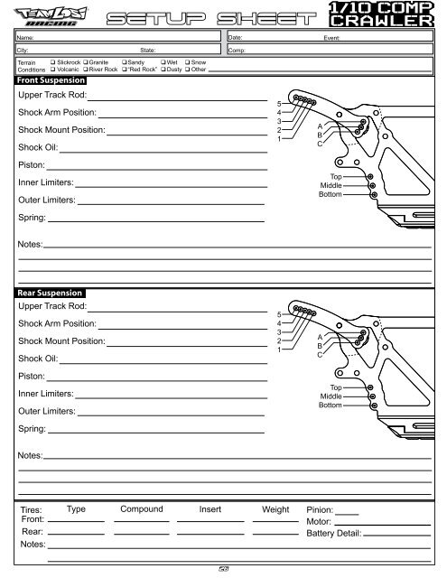
Setup Sheet<br />
<strong>Comp</strong>:<br />
Terrain<br />
Conditions<br />
Slickrock<br />
Volcanic<br />
Granite<br />
River Rock<br />
Sandy<br />
“Red Rock”<br />
Wet<br />
Dusty<br />
Snow<br />
Other<br />
Upper Track Rod:<br />
Shock Arm Position:<br />
Shock Mount Position:<br />
Shock Oil:<br />
Piston:<br />
Inner Limiters:<br />
Outer Limiters:<br />
Spring:<br />
5<br />
4<br />
3<br />
2<br />
1<br />
A<br />
B<br />
C<br />
Top<br />
Middle<br />
Bottom<br />
Upper Track Rod:<br />
Shock Arm Position:<br />
Shock Mount Position:<br />
Shock Oil:<br />
Piston:<br />
Inner Limiters:<br />
Outer Limiters:<br />
Spring:<br />
5<br />
4<br />
3<br />
2<br />
1<br />
A<br />
B<br />
C<br />
Top<br />
Middle<br />
Bottom<br />
Weight<br />
Pinion:<br />
Motor:<br />
Battery Detail:<br />
26
UNITED STATES:<br />
47<strong>10</strong> E. Guasti Road<br />
Ontario, CA 91761<br />
Phone: 909-390-9595<br />
Fax: 909-390-5356<br />
UNITED KINGDOM:<br />
Units 1-4 Ployters Rd<br />
Staple Tye<br />
Harlow, Essex<br />
CM18 7NS<br />
Phone: +44 (0) 1279 641 097<br />
800-0395 R5816T<br />
WWW.LOSI.COM<br />
E-mail - feedback@losi.com
1/<strong>10</strong>-SCALE COMPETITION ROCK CRAWLING CHASSIS<br />
OWNER’S MANUAL
q<br />
STEP I-01<br />
INTRO<br />
Intro to the <strong>Comp</strong> <strong>Crawler</strong> <strong>Manual</strong><br />
Welcome <strong>Team</strong> <strong>Losi</strong> <strong>Racing</strong> <strong>Comp</strong> <strong>Crawler</strong> Owner!<br />
Thank you for selecting the <strong>Comp</strong> <strong>Crawler</strong> as your new rock crawler. The <strong>Comp</strong> <strong>Crawler</strong> has already distinguished itself as a top caliber<br />
crawling chassis and as you will see, we have made every effort to produce a kit that is not only the most competitive but also easy to<br />
maintain. The simple step-by-step assembly sequence and easily followed instructions and drawings combined with <strong>Team</strong> <strong>Losi</strong> <strong>Racing</strong> world<br />
famous quality fitting parts will make using the <strong>Comp</strong> <strong>Crawler</strong> most enjoyable.<br />
Please take a moment to read through the following instructions. This will familiarize you with the various parts, assembly tips, and descriptions<br />
as well as the tools needed. Taking an extra moment before using your vehicle will help you understand the dynamics of the <strong>Comp</strong><br />
<strong>Crawler</strong>.<br />
Good luck,<br />
<strong>Team</strong> <strong>Losi</strong> <strong>Racing</strong><br />
STAY CONNECTED - REGISTER YOUR PRODUCT ONLINE:<br />
Register your product online so we can notify you about the latest option parts, product updates, tech tips, service bulletins and more. Visit<br />
WWW.LOSI.COM and follow the Product Registration link to stay connected.<br />
COMP CRAWLER COMPLETED KIT SPECIFICATIONS<br />
Overall Chassis Length: 14.12 in (358.6mm) Wheelbase: 12.30 in (312.4mm) *Front Track Width: 9.875in (250.8mm)<br />
Overall Length w/Tires: 17.5 in (431mm) *Overall Height: 6.75 in (172.8mm) *Rear Track Width: 9.875in (250.8mm)<br />
Note: Final vehicle weight will vary depending on accessories used.<br />
Table 1: <strong>Comp</strong> <strong>Crawler</strong> <strong>Comp</strong>leted Vehicle Specifications.<br />
<strong>Manual</strong> Organization:<br />
The manual is composed of different steps marked A through H.<br />
Each step contains all of the parts necessary to complete a particular<br />
section of the vehicle. Some of these steps have sub-assembly steps<br />
within them. It is helpful to read through the instructions for an entire<br />
step prior to working on your vehicle. Next to each of the step numbers<br />
is a check box. At the completion of each step, place a check in<br />
this box so that if you must stop and come back to the assembly, you<br />
will be able to pick up where you left off.<br />
For your convenience, an actual-size Hardware Identification<br />
Guide is included as a fold-out page at the back of this manual. Hardware<br />
that is not easily differentiable in each step is called out with an<br />
icon which contains a small picture of the part genre (referenced on<br />
the Hardware Identification Guide), the quantity of that part required<br />
for what is shown in the step,<br />
and the size or name of that<br />
part. To check a part, hold it<br />
against the silhouette until the<br />
correct part is identified. Associated<br />
with each of these parts,<br />
in the Hardware Identification Guide, is a LOSA-Number which is<br />
used when ordering replacement parts for your <strong>Comp</strong> <strong>Crawler</strong>. In<br />
some cases, extra hardware has been supplied for parts that may be<br />
easy to lose.<br />
<strong>Comp</strong>onents used in each step are identified by their relative<br />
LOSA-Number and the component’s name. With the exception of<br />
a few parts, these are not referenced in the Hardware Identification<br />
Guide.<br />
The molded parts in <strong>Team</strong> <strong>Losi</strong> <strong>Racing</strong> vehicles are manufactured<br />
to demanding tolerances. When screws are tightened to the<br />
point of being snug, the parts are held firmly in place. For this reason,<br />
it is very important that screws not be overtightened in any of the<br />
plastic parts.<br />
In some steps there will be a filled black circle with a white<br />
number. These indicate the specific order by which assembly must<br />
occur. In cases where steps are repeated (front/rear or left/right) these<br />
numbers may be omitted. Please note that these numbers will not call<br />
out every sub-step required for the step’s assembly procedures, they<br />
will only highlight the critical order required for assembly.<br />
In each step, there are specific “Detail Icons” (shaped like a stop<br />
sign) that call out critical precautions or assembly tips for the process.<br />
There is a reference key that describes the meaning of each of<br />
the icons located on the fold-out Hardware Identification Guide at<br />
the back of this manual.<br />
To ensure that parts are not lost during construction, it is recommended<br />
that you work over a towel or mat to prevent parts from<br />
rolling away.<br />
IMPORTANT SAFETY NOTES:<br />
1. Select an area for assembly that is away from the reach of small<br />
children. Some parts in this vehicle are small and can be swallowed<br />
by children, causing choking and possible internal injury;<br />
PLEASE USE CAUTION!<br />
2. The shock fluid and greases supplied should be kept out of children’s<br />
reach. They are not intended for human consumption!<br />
3. Exercise care when using any hand tools, sharp instruments, or<br />
power tools during construction.<br />
4. Carefully read all manufacturer’s warnings and cautions for any<br />
chemicals, glues, or paints that may be used for assembly and<br />
operating purposes.
Kit SETUP<br />
<strong>Comp</strong>:<br />
Terrain<br />
Conditions<br />
Slickrock<br />
Volcanic<br />
Granite<br />
River Rock<br />
Sandy<br />
“Red Rock”<br />
Wet<br />
Dusty<br />
Snow<br />
Other<br />
Upper Track Rod:<br />
Shock Arm Position:<br />
Shock Mount Position:<br />
Shock Oil:<br />
Piston:<br />
Inner Limiters:<br />
Outer Limiters:<br />
Spring:<br />
5<br />
4<br />
3<br />
2<br />
1<br />
A<br />
B<br />
C<br />
Top<br />
Middle<br />
Bottom<br />
Upper Track Rod:<br />
Shock Arm Position:<br />
Shock Mount Position:<br />
Shock Oil:<br />
Piston:<br />
Inner Limiters:<br />
Outer Limiters:<br />
Spring:<br />
5<br />
4<br />
3<br />
2<br />
1<br />
A<br />
B<br />
C<br />
Top<br />
Middle<br />
Bottom<br />
Rock Claws Blue Gray <strong>Losi</strong><br />
Weight<br />
None<br />
Rock Claws Blue Gray <strong>Losi</strong> None<br />
Pinion:<br />
Motor:<br />
Battery Detail:<br />
24
L<br />
HARDWARE<br />
Cap Head Flat Head Button Head<br />
Ball Bearings<br />
2-56 x 1/4” (A6232)<br />
2-56 x 5/16” (A6258)<br />
4-40 x 5/16” (A6245)<br />
4mm x 8mm(B1430)<br />
2-56 x 3/16” (A3186)<br />
2-56 x 5/16” (A6294)<br />
4-40 x 3/8” (A6206)<br />
4-40 x 1/2” (A6204)<br />
4-40 x 5/8” (A6221)<br />
4-40 x 3/4” (A6205)<br />
4-40 x 1/4” (A6213)<br />
4-40 x 5/16” (A6269)<br />
4-40 x 3/8” (A62<strong>10</strong>)<br />
3mm x 6mm (A6267)<br />
3mm x <strong>10</strong>mm (A6267)<br />
4-40 x 1 1/4” (A6268)<br />
4-40 x 3/8” (A6229)<br />
4-40 x 1/2” (A6256)<br />
4-40 x 5/8” (A6283)<br />
5mm x <strong>10</strong>mm (A6937)<br />
5mm x 11mm (A6947)<br />
6mm x <strong>10</strong>mm (A6946)<br />
Ball Studs Washers Metal Spacers<br />
6mm x 12mm (A6940)<br />
3/16” Standard Neck (A6001)<br />
1/8” x .020” Stainless (A6350)<br />
.198”x.256”x.188” (A3185)<br />
.198”x.256”x.5.00”<br />
(A3185)<br />
<strong>10</strong>mm x 15mm (A6943)<br />
4.1 x 5.5 x 2.0mm (A3183)<br />
5 x 7 x 0.2mm (A6358)<br />
12mm x 18mm (A6956)<br />
12 x 14 x .02mm<br />
(A6358)<br />
Set<br />
Roll/Solid Pins Retaining Clips Nuts (Lock/Plain)<br />
4-40 x 3/32” (A3194)<br />
9.5mm x 1.5mm Solid (A3194)<br />
1/8” E-Clip (A6<strong>10</strong>0)<br />
L 4-40 x 3/16” (Mini) (A6306)<br />
4-40 x 1/8” (A6227)<br />
4-40 x 3/16” (A6248)<br />
11mm x 1.5mm Solid (A3194)<br />
5mm E-Clip (A6<strong>10</strong>9)<br />
L 4-40 x 1/4” (A6308)<br />
4-40 x 5/8” (A6248)<br />
4-40 x 1” (A3167)<br />
5-40 x 5/8” (A6011)<br />
2.83mm x 25.9mm Solid (A<strong>10</strong>34)<br />
5.98mm x 21mm Solid (A3167)<br />
Body Clip (A8200)<br />
L 5mm, Flanged (A6321)(Black)<br />
5-40 x 1/8” (A6228)<br />
DETAIL ICON REFERENCE KEY<br />
1 These numbers are used to identify the critical order in which assembly must occur. *Note: They will not call out every stage of the assembly process.<br />
LOSI-LOK<br />
Apply <strong>Losi</strong>-Lok®<br />
CLEAR<br />
GREASE<br />
Apply Clear<br />
Grease<br />
GLUE<br />
Apply CA Glue<br />
GREASE<br />
Apply Synthetic<br />
White Grease<br />
OIL<br />
Fill With<br />
Silicone Oil<br />
Pre-Tap<br />
Pay Special<br />
Attention CUT Cut/Trim<br />
Ensure Free<br />
Movement<br />
Ensure Free<br />
Rotation<br />
Ensure Proper<br />
Orientation<br />
Push Firm<br />
L<br />
Side Shown<br />
x2<br />
L<br />
R<br />
R<br />
Assemble Other<br />
Side the Same<br />
Repeat/Build<br />
Multiple<br />
Screw Partially<br />
DO NOT<br />
Over Tighten/<br />
Snug Tight<br />
Tighten<br />
25
INTRO<br />
TOOLS REQUIRED FOR ASSEMBLY<br />
<strong>Team</strong> <strong>Losi</strong> <strong>Racing</strong> has supplied Allen wrenches that are needed for assembly and adjustments. The following common tools will also be<br />
required: needle-nose pliers, regular pliers, hobby knife, scissors or other body cutting/trimming tools, and a soldering iron may be necessary<br />
for radio installation. 3/16”, 1/4”, and 7mm nut drivers are optional.<br />
RADIO/ELECTRONICS<br />
A suggested radio layout is provided in this manual. Your hobby shop should be consulted regarding specific questions pertaining to radio/<br />
electrical equipment.<br />
HARDWARE IDENTIFICATION<br />
When in question, use the Hardware Identification Guide at the back of this manual.<br />
• For screws, the prefix number designates the thread size and number of threads per inch (e.g., 4-40 is a #4 size thread with 40 threads per<br />
inch). The second number, or fraction, designates the length of the screw. For cap head and button head screws, this number refers to the<br />
length of the threaded portion of the screw. For flat head and setscrews, this number refers to the overall length of the screw.<br />
• Bearings and bushings are referenced by the inside diameter (I.D.) x outside diameter (O.D.).<br />
• Shafts and pins are designated by type (Roll, Solid) and referenced by diameter x length.<br />
• Washers, Spacers and Shims are described by inside diameter or the screw size that will pass through the inside diameter x the thickness<br />
or by their designated application (e.g., Ball Stud washer is primarily used under a Ball Stud).<br />
• Retaining Clips are sized by the shaft diameter that they attach to or by type (Body). The Hardware Icon associated with E/C-Clips only<br />
designates the part genre of clips, not the actual part.<br />
• Nuts come in four types, Non-Flanged, Flanged (F), Plain, and Locking (L) (designated on the Hardware Icons). The prefix number designates<br />
the thread size and number of threads per inch. The second number, or fraction, designates the size of the hex. For example, L 4-40<br />
x 1/4” designates a Lock nut that will thread onto a 4-40 screw using a 1/4” nut driver.<br />
• Ball studs are described by the length of the neck between the base and the bottom of the ball (i.e., standard, short) and the length of the<br />
threaded portion.<br />
TABLE OF CONTENTS<br />
SECTIONS<br />
1. INTRODUCTION................................................... i<br />
Kit/<strong>Manual</strong> Organization.................................... i<br />
Important Safety Notes....................................... i<br />
Tools Required for Assembly............................ ii<br />
Radio/Electronics.............................................. ii<br />
Hardware Identification..................................... ii<br />
2. Step A: Front Axle............................................... 1-3<br />
3. Step B: Rear Axle................................................ 4-5<br />
4. Step C: Chassis.................................................... 6-8<br />
5. Step D: Transmission......................................... 9-11<br />
6. Step E: Driveshafts/Suspension Links............. 12-14<br />
7. Step F: Shocks................................................. 15-16<br />
8. Step G: Tire & Wheels..................................... 17-18<br />
9. Step H: Body.........................................................19<br />
<strong>10</strong>. Checklist & Tips...................................................20<br />
11. Warranty......................................................... 21-22<br />
12. Notes.......................................................................23<br />
<strong>10</strong>. Filled-out <strong>Comp</strong> <strong>Crawler</strong> Setup Sheet ................24<br />
13. Hardware Identification Guide...........................25<br />
14. Blank <strong>Comp</strong> <strong>Crawler</strong> Setup Sheet........................26<br />
<strong>Team</strong> <strong>Losi</strong> <strong>Racing</strong> is continually changing and improving designs; therefore, the actual part may appear slightly different than the illustrated part. Illustrations of parts and<br />
assemblies may be slightly distorted to enhance pertinent details.<br />
ii<br />
TABLES<br />
Table 1: <strong>Comp</strong> <strong>Crawler</strong> <strong>Comp</strong>leted Kit Specifications i<br />
Table 2: Gear Ratios...................................................20
q<br />
STEP A-01<br />
Step A<br />
Front Spindle & CV Assembly<br />
A3192<br />
CV Driveshaft<br />
A3194<br />
Solid<br />
x1<br />
1.5mm x 11mm<br />
2<br />
3<br />
A3194<br />
CV Coupler<br />
A3191<br />
CV Axle<br />
A6940<br />
x1<br />
6mm x12mm<br />
A<strong>10</strong>30<br />
Spindle<br />
4<br />
1<br />
5<br />
A6937<br />
x1<br />
A6358<br />
x1<br />
5mm x<strong>10</strong>mm<br />
5x7x.2mm<br />
8<br />
A3186<br />
x1<br />
2-56” x 3/16”<br />
A3186<br />
12mm Hex<br />
6 7<br />
A3194<br />
Solid<br />
x1<br />
1.5mm x 9.5mm<br />
q<br />
STEP A-02<br />
Front Axle Assembly<br />
A6206<br />
x4<br />
4-40” x 3/8”<br />
A6956<br />
x2<br />
12x8x4mm<br />
A6358<br />
x2<br />
12x4x.2mm<br />
A4012<br />
Housing<br />
A6947<br />
x2<br />
5x11x4mm<br />
A3175<br />
Worm Pinion Gear<br />
A6358<br />
x6<br />
5x7x.2mm<br />
A3174<br />
Worm Gear (Spool)<br />
A6294<br />
x2<br />
2-56” x 5/16”
q<br />
STEP A-03<br />
Spindle/Carrier Assembly<br />
A6221<br />
4-40” x 5/8”<br />
A6206<br />
x2<br />
x2<br />
4-40” x 3/8”<br />
Step A<br />
A62<strong>10</strong><br />
x1<br />
4-40” x 3/8”<br />
A<strong>10</strong>37<br />
Servo Platform<br />
A<strong>10</strong>33<br />
Upper Link Mount<br />
A1517<br />
King Pin<br />
A<strong>10</strong>30<br />
Castor Block<br />
A6256<br />
x2<br />
4-40” x 1/2”<br />
A6248<br />
x2<br />
4-40” x 3/16”<br />
q<br />
•<br />
•<br />
•<br />
•<br />
The <strong>Comp</strong> <strong>Crawler</strong> includes 23T and 24T<br />
Aluminum servo arms. Use the following information<br />
to install the correct servo arm for<br />
your servo:<br />
JR, Airtronics & KO PROPO Servos: 23T<br />
Hitec Servos: 24T<br />
Futaba Servos: 25T (LOSA99039) Not Included<br />
Ensure the servo gear is centered before attaching<br />
the Servo Horn. This is best accomplished<br />
by connecting the servo to the radio<br />
system and setting the trim to center.<br />
•<br />
STEP A-04<br />
Servo/Steering Linkage Assembly<br />
A1522<br />
Steering Bushing<br />
A6044<br />
Rod End Ball<br />
A6044<br />
Rod End<br />
A6350<br />
x6<br />
1/8” x 0.020”<br />
A1520<br />
Drag Link<br />
A6256<br />
x3<br />
4-40” x 1/2”<br />
2<br />
A<strong>10</strong>37<br />
Servo Platform<br />
A99037<br />
Servo Arm<br />
1<br />
A6306<br />
x3<br />
L 4-40 x 3/16”<br />
A6206<br />
x2<br />
4-40” x 3/8”<br />
A1522<br />
Steering Knuckle<br />
A6043<br />
x4<br />
5-40” x 5/8”<br />
A1521<br />
Steering Rod<br />
A6308<br />
x2<br />
L 4-40 x 1/4”<br />
A1522<br />
Steering Knuckle
q<br />
STEP A-05<br />
Step A<br />
<strong>Comp</strong>leted Front Axle Assembly<br />
L
q<br />
STEP B-01<br />
Rear Axle Assembly<br />
Step B<br />
A6294<br />
x2<br />
2-56” x 5/16”<br />
A6956<br />
x2<br />
12x8x4mm<br />
A6358<br />
x2<br />
12x4x.2mm<br />
A4012<br />
Housing<br />
A6947<br />
x2<br />
5x11x4mm<br />
A3175<br />
Worm Pinion Gear<br />
A6358<br />
x6<br />
5x7x.2mm<br />
A3174<br />
Worm Gear (Spool)<br />
A6206<br />
x4<br />
4-40” x 3/8”<br />
q<br />
STEP B-02<br />
Rear Hub Assembly<br />
A2030<br />
Rear Hub<br />
2<br />
A3194<br />
Solid<br />
x1<br />
1.5mm x 9.5mm<br />
A6937<br />
x2<br />
5 x <strong>10</strong>mm<br />
A3184<br />
Rear Axle<br />
A3185<br />
Axle Spacer<br />
A3185<br />
Axle Spacer<br />
1<br />
4<br />
A6268<br />
x2<br />
4-40” x 1 1/4”<br />
3
q<br />
STEP B-03<br />
Step B<br />
Upper Link Mount/ESC Plate<br />
A62<strong>10</strong><br />
x1<br />
4-40” x 3/8”<br />
A6221<br />
x2<br />
4-40” x 5/8”<br />
A4036<br />
ESC Platform<br />
A<strong>10</strong>33<br />
Upper Link Mount<br />
A6206<br />
x2<br />
4-40” x 3/8”<br />
q<br />
STEP B-04<br />
<strong>Comp</strong>leted Rear Axle Assembly
q<br />
STEP C-01<br />
Chassis Plate Assembly<br />
Step C<br />
A6283<br />
A4035<br />
Body Post<br />
A4035<br />
Platform<br />
x4<br />
4-40” x 5/8”<br />
A1<strong>10</strong>3<br />
Arm Spacer<br />
A1<strong>10</strong>3<br />
Shock Arm<br />
A6245<br />
x2<br />
4-40” x 5/16”<br />
A8200<br />
Body Clip<br />
A6256<br />
x2<br />
4-40” x 1/2”<br />
A4011<br />
Chassis Plate<br />
A6308<br />
x6<br />
L 4-40 x 1/4”<br />
A6043<br />
x4<br />
5-40” x 5/8”<br />
A<strong>10</strong>32<br />
Track Rod<br />
A6044<br />
Rod End<br />
A6044<br />
Pivot Ball<br />
x2<br />
q<br />
STEP C-02<br />
Chassis Assembly<br />
A6229<br />
x4<br />
4-40” x 3/8”<br />
LOSA4034<br />
Chassis<br />
Brace Rod<br />
A4039<br />
Skid Plate<br />
A6213<br />
x4<br />
4-40” x 1/4”
q<br />
STEP C-03<br />
Lower Link Assembly<br />
Step C<br />
A<strong>10</strong>34<br />
Solid<br />
x2<br />
1/8” x 1”<br />
A6043<br />
A<strong>10</strong>34<br />
Link Mount<br />
x8<br />
5-40” x 5/8”<br />
A6269<br />
x4<br />
4-40” x 5/16”<br />
A6011<br />
17° Rod End<br />
A<strong>10</strong>31<br />
Track Rod<br />
A<strong>10</strong>34<br />
Link Mount<br />
q<br />
STEP C-04<br />
Platform Assembly<br />
A4032<br />
Receiver Platform<br />
A6248<br />
x1<br />
4-40” x 1/8”<br />
A4032<br />
Wire Clamp<br />
A6229<br />
x8<br />
4-40” x 3/8”<br />
A4009<br />
Battery Strap<br />
A4032<br />
Battery Platform<br />
A6294<br />
x4<br />
2-56” x 5/16”
q<br />
STEP C-05<br />
Step C<br />
<strong>Comp</strong>leted Chassis Assembly
q<br />
STEP D-01<br />
“Dig” Drive Assembly<br />
Step D<br />
A6<strong>10</strong>9<br />
5mm<br />
x1<br />
A3178<br />
Dig Spring<br />
A3178<br />
Dig Plate<br />
A3167<br />
Main Dig Shaft<br />
B1430<br />
4 x 8mm<br />
x2<br />
A3166<br />
Dig Gear<br />
A3183<br />
Outdrive<br />
A6943<br />
x2<br />
<strong>10</strong>x15mm<br />
A3183<br />
x1<br />
5.5x4x2mm<br />
q<br />
STEP D-02<br />
Inner Transmission Assembly<br />
A6<strong>10</strong>0<br />
1/8”<br />
x2<br />
A3165<br />
Outer Case<br />
A3179<br />
“Dig” Shaft<br />
A3166<br />
Top Shaft Gear<br />
A3165<br />
Center Section<br />
A3179<br />
“Dig” Fork<br />
A3167<br />
Top Shaft<br />
A6<strong>10</strong>9<br />
5mm<br />
x1<br />
A6940<br />
6x12mm<br />
x2<br />
A3167<br />
x1<br />
4-40” x 1”<br />
A6256<br />
x3<br />
4-40” x 1/2”
q<br />
STEP D-03<br />
Step D<br />
Outer Transmission Assembly<br />
A3166<br />
Idler Gear<br />
A3167<br />
Idler Shaft<br />
A6947<br />
x2<br />
5x11x4mm<br />
A6221<br />
x3<br />
4-40” x 5/8”<br />
A3170<br />
Slipper Gear<br />
A3171<br />
Slipper Pad<br />
A6308<br />
x1<br />
L 4-40 x 1/4”<br />
A3165<br />
Outer Trans Case<br />
A3170<br />
Slipper Spacer<br />
A3170<br />
Slipper Plate<br />
q STEP D-04 “DIG” Servo Installation<br />
• To take advantage of the <strong>Comp</strong> <strong>Crawler</strong>s<br />
2mm<br />
“front & rear” dig setup, a Radio System<br />
such as the Spektrum DX3R with a 3-position<br />
Aux channel is required. A 2-position<br />
Aux channel can be used as well, however<br />
only “front” dig can be used.<br />
• If you will not be using the optional Dig<br />
system, remove the small tie rod attached<br />
to the shift horn.<br />
• A <strong>Losi</strong> MSX12 (LOSB0822) Mini Digital<br />
6mm<br />
Servo is required to use the dig options.<br />
Front “Dig”<br />
• Caution: When setting up the <strong>Comp</strong><br />
<strong>Crawler</strong> with dig, it is important to set<br />
your AUX channels Travel/EPA (End<br />
Point Adjustment) to “Zero” in any<br />
direction. If this is not done, servo failure<br />
can occur.<br />
• Once the proper dig arm is attached to your<br />
servo (<strong>Losi</strong>, JR, Airtronics & KO Propo<br />
23T, Hitec 24T, Futaba 25T) and is centered,<br />
you can now adjust the Travel/EPA<br />
5.5mm<br />
settings for each direction. While adjusting<br />
the travel, note that once the Dig shaft<br />
stops moving, you can stop adjustment.<br />
If any more travel is set, the Mini Servo<br />
could encounter damage.<br />
Full Time<br />
4wd<br />
Rear “DIG”<br />
A4038<br />
x1<br />
4-40” x 5/8”<br />
A6001<br />
x2<br />
3/16”<br />
A4038<br />
Rod End<br />
A4038<br />
Shift Horn<br />
A6306<br />
x1<br />
L 4-40 x 3/16”<br />
A4038<br />
Dig Arm<br />
A6350<br />
x6<br />
1/8” x .020”<br />
A6229<br />
x6<br />
4-40” x 3/8”<br />
A6308<br />
x2<br />
L 4-40 x 1/4”<br />
<strong>10</strong>
Step D<br />
q STEP D-05 Motor Installation<br />
• When setting the gear mesh, leave a small amount of backlash<br />
for proper function. Too much backlash will cause failure,<br />
so be sure to check the mesh at different points in the<br />
rotation of the Idler Gear.<br />
• Make sure to tighten motor clamp screws properly to ensure<br />
the motor plate does not spin under heavy loads and compromise<br />
the gear mesh.<br />
A6206<br />
x2<br />
4-40” x 3/8”<br />
MOTOR<br />
NOT INCLUDED<br />
A6204<br />
x2<br />
4-40” x 1/2”<br />
A6267<br />
3 x 6mm<br />
x1<br />
A3165<br />
Motor Clamp<br />
A3169<br />
Motor Plate<br />
GEAR NOT<br />
INCLUDED<br />
A6267<br />
x1<br />
3 x <strong>10</strong>mm<br />
q<br />
STEP D-06<br />
<strong>Comp</strong>leted Trans Assembly<br />
11
q<br />
STEP E-01<br />
Transmission Installation<br />
Step E<br />
A6269<br />
x4<br />
4-40” x 5/16”<br />
q<br />
STEP E-02<br />
Driveshaft Assembly<br />
A3194<br />
Solid<br />
x2<br />
1.5 x 9.5mm<br />
A3193<br />
Cup Driveshaft Yoke<br />
A3165<br />
Coupler<br />
A3168<br />
Male Driveshaft<br />
A3193<br />
Ball Driveshaft Yoke<br />
A3194<br />
x2<br />
4-40” x 3/32”<br />
A3168<br />
Female Driveshaft<br />
A6204<br />
x2<br />
4-40” x 1/2”<br />
x2<br />
12
Step E<br />
q<br />
STEP E-03<br />
Front Driveshaft Install<br />
q<br />
STEP E-04<br />
Rear Driveshaft Install<br />
A6228<br />
x2<br />
5-40” x 1/8”<br />
A6228<br />
x2<br />
5-40” x 1/8”<br />
q<br />
STEP E-05<br />
Front & Rear Axle Installtion<br />
E-01B<br />
E-01A<br />
A6228<br />
x4<br />
5-40” x 1/8”<br />
A6350<br />
x4<br />
1/8 x 0.020”<br />
A6221<br />
x4<br />
4-40” x 5/8”<br />
x2<br />
DETAIL E-01B<br />
A6308<br />
x4<br />
L 4-40 x 1/4”<br />
DETAIL E-01A<br />
13
q STEP E-06<br />
Step E<br />
<strong>Comp</strong>leted Chassis Assembly<br />
14
q<br />
STEP F-01<br />
Shock Assembly<br />
Step F<br />
•<br />
•<br />
•<br />
•<br />
•<br />
Holding the shock body inverted, fill the Shock Body with Shock Oil up to the bottom of the threads inside the Shock Body.<br />
Insert shaft assembly with cartridge against the shock piston.<br />
Slowly tighten the Cartridge until it almost bottoms against the Shock Body. Do not tighten all the way.<br />
Slowly push Shock Shaft assembly into the Shock Body. This will bleed the excess oil out of the Shock.<br />
Once the Shaft is pushed all the way down into the Shock Body, tighten the Shock Cartridge the rest of the way with a 7/16” wrench or a<br />
pair of pliers approximately 1/8th of a turn.<br />
There should be no air in the Shocks as you move the Shaft in and out of the Shock Body. If there is, you will need to add some Oil and<br />
repeat the bleed process. If the Shock does not compress all the way, the shock has too much Oil. Simply loosen the Cartridge about 1/4<br />
turn and push the Shaft into the Body and retighten the Cartridge.<br />
•<br />
A5012<br />
Ball Joint<br />
A5079<br />
Shock End<br />
A5056<br />
Shock Body<br />
A5147<br />
Spring, White<br />
A5062<br />
Shock Shaft<br />
A5079<br />
Spring Cup<br />
A5015<br />
Shock Cartridge<br />
A5049<br />
Spring Adjustment<br />
Nut<br />
A5056<br />
Shock Piston, #56<br />
A6<strong>10</strong>0<br />
x2<br />
1/8” E-Clip<br />
15
q<br />
STEP F-02<br />
Shock Installation<br />
Step F<br />
A4033<br />
Shock Brace<br />
Rod<br />
A6221<br />
x4<br />
4-40” x 5/8”<br />
A5012<br />
Shock Bushing<br />
A6350<br />
x4<br />
1/8 x 0.020”<br />
A6221<br />
x4<br />
4-40” x 5/8”<br />
A6308<br />
x4<br />
L 4-40 x 1/4”<br />
x2<br />
q<br />
STEP F-03<br />
<strong>Comp</strong>leted Shock Assembly<br />
16
q<br />
STEP G-01<br />
6<br />
5<br />
Tire & Wheel Assembly<br />
Step G<br />
• Tighten Beadlock rings using<br />
the sequence shown.<br />
4<br />
2<br />
1<br />
1<br />
6<br />
3<br />
5<br />
2<br />
3<br />
4<br />
q<br />
STEP G-02<br />
Tire Installation<br />
A6321<br />
L 5mm<br />
x4<br />
x4<br />
17
q<br />
STEP G-03<br />
Step G<br />
Suggested Electronics Layout<br />
q STEP G-04<br />
<strong>Comp</strong>leted Tire & Electronics<br />
18
q STEP H-01<br />
Painting the Body<br />
Step H<br />
Painting:<br />
Prepare the Polycarbonate Body for painting by washing it thoroughly (inside and out) with warm water and liquid detergent. Dry the<br />
Body with a clean, soft cloth. Use the supplied Window Masks to cover the windows from the inside. A high-quality masking tape should<br />
be used on the inside of the Body to mask off any stripes, panels, or designs that you wish to paint on the Body. Use acrylic lacquer or other<br />
paints recommended for polycarbonate. (NOTE: Polycarbonate RC CAR BODIES ARE MEANT TO BE PAINTED FROM THE IN-<br />
SIDE!) Apply paint to the inside of the Body. Remove the masking tape for the next color and continue. Try to use darker colors first. If you<br />
use a dark color after a light color, apply a coat of white paint over the lighter color before applying the darker color, or if you are painting<br />
over white, coat it with silver. This will help prevent the darker color from bleeding through the lighter color.<br />
Stickers:<br />
After the Body is mounted, REMOVE THE PROTECTIVE FILM ON THE OUTER SURFACE, now you can apply the stickers.<br />
Remove the sticker from the sheet that you wish to apply to the Body. Before removing the protective backing, find the desired location.<br />
Remove the backing completely and reattach an edge of the sticker to the shiny side of the backing material. Using the rest of the backing<br />
material as a handle, position the sticker and press firmly into place to complete its application.<br />
19
ChecklIST<br />
BEFORE RUNNING YOUR NEW COMP CRAWLER ROCK CRAWLER for the first time, you should run down the following checklist<br />
in order and complete the listed tasks. We’re sure you’re anxious to get out and run your new <strong>Comp</strong> <strong>Crawler</strong> now that its built, but please<br />
note that fine-tuning of the initial setup is an essential part of building a high-performance rock crawler such as your new <strong>Comp</strong> <strong>Crawler</strong>.<br />
Following this simple Checklist and the <strong>Team</strong> Tips will help to make the first run with your new rig much more enjoyable.<br />
1. Check for free suspension movement:<br />
All suspension arms and steering components should move freely. Any binds will cause the crawler to handle poorly.<br />
2. Charge a battery pack:<br />
Charge a battery pack as per the battery manufacturer’s and/or charger manufacturer’s instructions so that radio adjustments can be<br />
made. Never plug the battery into the speed control backwards.<br />
3. Adjust the electronic speed control (ESC):<br />
Following the manufacturer’s instructions, adjust your speed control and set the throttle trim on your ESC so that the crawler does not<br />
creep forward or backward when no transmitter input is applied.<br />
4. Set the transmitter steering and throttle trim:<br />
The steering trim tab on the transmitter should be adjusted so that the crawler moves straight when you are not touching the steering<br />
wheel/stick. If the servo and steering link were installed correctly, the wheels should turn equally to the left and right. Make sure the<br />
throttle trim is set so that the motor does not run when in the neutral position.<br />
5. Adjust the Dig Servo:<br />
It is important that the Dig servo travel is set correctly. With all 4 tires of the <strong>Comp</strong> <strong>Crawler</strong> off the ground and the ESC switched on,<br />
engage the dig forward. Only the front tires should have power. Returning the dig servo arm to center should provide power to both<br />
front and rear axles. With the dig servo arm engaged towards the rear, only the rear tires should have power. It is critical that the servo is<br />
adjusted correctly. If too much travel is dialed in, this can cause a load on the servo that could cause damage to the servo.<br />
The <strong>Team</strong> <strong>Losi</strong> <strong>Racing</strong> <strong>Comp</strong> <strong>Crawler</strong> has been designed to be a <strong>Comp</strong> Ready Rock <strong>Crawler</strong> that eliminates the guess work of chosing the<br />
“right chassis” to be competitive. We have optimized the ground clearance, steering throw and suspension geometery. The entire package has<br />
been designed as a leaner/lighter Rock <strong>Crawler</strong>. It is not necessary to run “extra heavy” aluminum wheels that in fact can hinder performance<br />
and create extra loads on the drivetrain. Below are some setup tips for your <strong>Comp</strong> <strong>Crawler</strong>:<br />
Setup Tips:<br />
Using the Dig: The <strong>Comp</strong> <strong>Crawler</strong>s unique Front and Rear Dig unit allows you to turn tighter and/or “wiggle” the rear into different positions<br />
on the rocks. Although the <strong>Comp</strong> <strong>Crawler</strong> can be shifted “on the fly” it is suggested that you stop or slow your “rig’ before engaging or<br />
disengaging the dig system. This will increase the longevity of the dig components.<br />
Upper Track Rods<br />
Front: Raising the front track rod from the middle hole will stiffen the front causing less chassis roll. This will make the <strong>Comp</strong> <strong>Crawler</strong><br />
feel stiffer without changing shock oil. Mouting the Track Rod in the lower position will cause more chassis roll and allow the front suspension<br />
to react more to obstacles.<br />
Rear: Raising the rear track rod from the middle hole will make the rear more stable with<br />
less tendency to move around (less traction). Mounting the Track Rod will create more traction,<br />
but also make the rear “sway” more allowing the <strong>Comp</strong> <strong>Crawler</strong> to articulate easier. To eliminate<br />
the extra “sway”, it is suggested to use a firmer spring or thicker oil.<br />
Shock Arm Position<br />
Raised Shock Arm: Raising the shock arm on the <strong>Comp</strong> <strong>Crawler</strong> will lower the chassis and<br />
center of gravity. This position is best for areas with smooth rocks and steep vertical climbs<br />
(slickrock, granite, etc:)<br />
Lowered Shock Arm: Lowering the shock arm will raise the chassis and provide more<br />
ground clearance. This is best for areas with jagged rocks without too many steep climbs (riverbeds,<br />
volcanic rocks, etc.<br />
Wheel Weights:<br />
By installing LOSA99201 “Self-Stick Chassis Weights” inside the wheel, overall traction<br />
can be improved. Our <strong>Team</strong> drivers in testing found that 6 ounces in the front wheels with 2.5<br />
ounces in each rear wheel is a great start. Depending on your terrain you may want to increase<br />
or decrease the weight.<br />
Motor/Battery Combo Suggestions:<br />
Although gearing will vary from motor/battery configurations, our <strong>Team</strong> Drivers have found<br />
that while using a 3S LiPo setup with a 21.5 brushless motor, a 18 tooth pinion provided a good<br />
wheel speed and torque. The same pinion also worked well with a 2S LiPo and an 18.5 brushless<br />
motor.<br />
20
WARRANTY<br />
Warranty Period<br />
Horizon Hobby, Inc., (Horizon) warranties that the Products purchased (the “Product”) will be free from defects in materials and workmanship at<br />
the date of purchase by the Purchaser.<br />
Limited Warranty<br />
(a) This warranty is limited to the original Purchaser (“Purchaser”) and is not transferable. REPAIR OR REPLACEMENT AS PROVIDED UNDER THIS<br />
WARRANTY IS THE EXCLUSIVE REMEDY OF THE PURCHASER. This warranty covers only those Products purchased from an authorized Horizon<br />
dealer. Third party transactions are not covered by this warranty. Proof of purchase is required for warranty claims. Further, Horizon reserves the<br />
right to change or modify this warranty without notice and disclaims all other warranties, express or implied.<br />
(b) Limitations- HORIZON MAKES NO WARRANTY OR REPRESENTATION, EXPRESS OR IMPLIED, ABOUT NON-INFRINGEMENT, MERCHANTABILITY<br />
OR FITNESS FOR A PARTICULAR PURPOSE OF THE PRODUCT. THE PURCHASER ACKNOWLEDGES THAT THEY ALONE HAVE DETERMINED THAT THE<br />
PRODUCT WILL SUITABLY MEET THE REQUIREMENTS OF THE PURCHASER’S INTENDED USE.<br />
(c) Purchaser Remedy- Horizon’s sole obligation hereunder shall be that Horizon will, at its option, (i) repair or (ii) replace, any Product determined<br />
by Horizon to be defective. In the event of a defect, these are the Purchaser’s exclusive remedies. Horizon reserves the right to inspect any and<br />
all equipment involved in a warranty claim. Repair or replacement decisions are at the sole discretion of Horizon. This warranty does not cover<br />
cosmetic damage or damage due to acts of God, accident, misuse, abuse, negligence, commercial use, or modification of or to any part of the<br />
Product. This warranty does not cover damage due to improper installation, operation, maintenance, or attempted repair by anyone other than<br />
Horizon. Return of any goods by Purchaser must be approved in writing by Horizon before shipment.<br />
Damage Limits<br />
HORIZON SHALL NOT BE LIABLE FOR SPECIAL, INDIRECT OR CONSEQUENTIAL DAMAGES, LOSS OF PROFITS OR PRODUCTION OR COMMERCIAL<br />
LOSS IN ANY WAY CONNECTED WITH THE PRODUCT, WHETHER SUCH CLAIM IS BASED IN CONTRACT, WARRANTY, NEGLIGENCE, OR STRICT<br />
LIABILITY. Further, in no event shall the liability of Horizon exceed the individual price of the Product on which liability is asserted. As Horizon has<br />
no control over use, setup, final assembly, modification or misuse, no liability shall be assumed nor accepted for any resulting damage or injury. By<br />
the act of use, setup or assembly, the user accepts all resulting liability.<br />
If you as the Purchaser or user are not prepared to accept the liability associated with the use of this Product, you are advised to return this<br />
Product immediately in new and unused condition to the place of purchase.<br />
Law: These Terms are governed by Illinois law (without regard to conflict of law principals).<br />
Safety Precautions<br />
This is a sophisticated hobby Product and not a toy. It must be operated with caution and common sense and requires some basic mechanical<br />
ability. Failure to operate this Product in a safe and responsible manner could result in injury or damage to the Product or other property. This<br />
Product is not intended for use by children without direct adult supervision. The Product manual contains instructions for safety, operation and<br />
maintenance. It is essential to read and follow all the instructions and warnings in the manual, prior to assembly, setup or use, in order to operate<br />
correctly and avoid damage or injury.<br />
Questions, Assistance, and Repairs<br />
Your local hobby store and/or place of purchase cannot provide warranty support or repair. Once assembly, setup or use of the Product has been<br />
started, you must contact Horizon directly. This will enable Horizon to better answer your questions and service you in the event that you may<br />
need any assistance. For questions or assistance, please direct your email to feedback@teamlosi.com, or call 888.899.LOSI(5674) toll free to speak<br />
to a service technician.<br />
Inspection or Repairs<br />
If this Product needs to be inspected or repaired, please call for a Return Merchandise Authorization (RMA). Pack the Product securely using a<br />
shipping carton. Please note that original boxes may be included, but are not designed to withstand the rigors of shipping without additional<br />
protection. Ship via a carrier that provides tracking and insurance for lost or damaged parcels, as Horizon is not responsible for merchandise<br />
until it arrives and is accepted at our facility. A Service Repair Request is available at www.horizonhobby.com on the “Support” tab. If you<br />
do not have internet access, please include a letter with your complete name, street address, email address and phone number where you can<br />
be reached during business days, your RMA number, a list of the included items, method of payment for any non-warranty expenses and a brief<br />
summary of the problem. Your original sales receipt must also be included for warranty consideration. Be sure your name, address, and RMA<br />
number are clearly written on the outside of the shipping carton.<br />
Warranty Inspection and Repairs<br />
To receive warranty service, you must include your original sales receipt verifying the proof-of-purchase date. Provided warranty<br />
conditions have been met, your Product will be repaired or replaced free of charge. Repair or replacement decisions are at the sole discretion of<br />
Horizon Hobby.<br />
Non-Warranty Repairs<br />
Should your repair not be covered by warranty the repair will be completed and payment will be required without notification or<br />
estimate of the expense unless the expense exceeds 50% of the retail purchase cost. By submitting the item for repair you are agreeing<br />
to payment of the repair without notification. Repair estimates are available upon request. You must include this request with your repair. Nonwarranty<br />
repair estimates will be billed a minimum of ½ hour of labor. In addition you will be billed for return freight. Please advise us of your<br />
preferred method of payment. Horizon accepts money orders and cashiers checks, as well as Visa, MasterCard, American Express, and Discover<br />
cards.<br />
If you choose to pay by credit card, please include your credit card number and expiration date. Any repair left unpaid or unclaimed after 90 days<br />
will be considered abandoned and will be disposed of accordingly. Please note: non-warranty repair is only available on electronics and<br />
model engines.<br />
21
WARRANTY<br />
Age Recommendation:<br />
14 years or over. This is not a toy. This product is not intended for use by children without direct adult supervision.<br />
22
23<br />
Setup Notes: ____________________________________________________________________________________________________<br />
________________________________________________________________________________________________________________<br />
________________________________________________________________________________________________________________________________<br />
________________________________________________________________________________________________________________________________<br />
________________________________________________________________________________________________________________________________<br />
________________________________________________________________________________________________________________________________<br />
________________________________________________________________________________________________________________________________<br />
________________________________________________________________________________________________________________________________<br />
________________________________________________________________________________________________________________________________<br />
________________________________________________________________________________________________________________________________<br />
________________________________________________________________________________________________________________________________<br />
________________________________________________________________________________________________________________________________<br />
________________________________________________________________________________________________________________________________<br />
________________________________________________________________________________________________________________________________<br />
_______________________________________________________________________________________________________________________________<br />
_______________________________________________________________________________________________________________________________<br />
_______________________________________________________________________________________________________________________________<br />
_______________________________________________________________________________________________________________________________<br />
_______________________________________________________________________________________________________________________________<br />
_______________________________________________________________________________________________________________________________<br />
_______________________________________________________________________________________________________________________________<br />
_______________________________________________________________________________________________________________________________<br />
_______________________________________________________________________________________________________________________________<br />
________________________________________________________________________________________________________________<br />
________________________________________________________________________________________________________________<br />
___________________________________________________________________________________________________________________________________________<br />
__________________________________________________________________________________________________________________________________________<br />
________________________________________________________________________________________________________________<br />
________________________________________________________________________________________________________________<br />
_________________________________________________________________________________________________________________________<br />
_________________________________________________________________________________________________________________________<br />
________________________________________________________________________________________________________________<br />
________________________________________________________________________________________________________________<br />
_________________________________________________________________________________________________________________________________________________<br />
________________________________________________________________________________________________________________________________________________<br />
________________________________________________________________________________________________________________<br />
________________________________________________________________________________________________________________<br />
________________________________________________________________________________________________________________________<br />
_______________________________________________________________________________________________________________________<br />
________________________________________________________________________________________________________________<br />
________________________________________________________________________________________________________________<br />
___________________________________________________________________________________________________________________________________________<br />
__________________________________________________________________________________________________________________________________________<br />
__________________________________________________________________________________________________________________________________________<br />
__________________________________________________________________________________________________________________________________________<br />
__________________________________________________________________________________________________________________________________________<br />
________________________________________________________________________________________________________________<br />
________________________________________________________________________________________________________________<br />
_______________________________________________________________________________________________________________________<br />
______________________________________________________________________________________________________________________<br />
_______________________________________________________________________________________________________________<br />
NOTES