M-Bus Master MultiPort 250D - Kamstrup
M-Bus Master MultiPort 250D - Kamstrup
M-Bus Master MultiPort 250D - Kamstrup

Create successful ePaper yourself
Turn your PDF publications into a flip-book with our unique Google optimized e-Paper software.
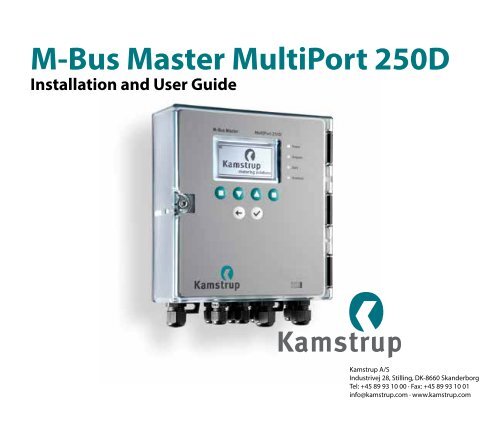
M-<strong>Bus</strong> <strong>Master</strong> <strong>MultiPort</strong> <strong>250D</strong><br />
Installation and User Guide<br />
<strong>Kamstrup</strong> A/S<br />
Industrivej 28, Stilling, DK-8660 Skanderborg<br />
Tel: +45 89 93 10 00 · Fax: +45 89 93 10 01<br />
info@kamstrup.com · www.kamstrup.com
Contents<br />
1 Introduction 4<br />
1.1 Design 4<br />
2 Functionality 5<br />
2.1 Overview of functions 7<br />
3 Connections 8<br />
3.1 Overview of connections 9<br />
3.2 Power supply 10<br />
3.3 USB 10<br />
3.4 RS-232 13<br />
3.5 RS-485 14<br />
3.6 Optical eye 14<br />
3.7 M-<strong>Bus</strong> Output 14<br />
3.7.1 Current and voltage 14<br />
3.8 M-<strong>Bus</strong> Repeater Input 15<br />
4 Cabling 16<br />
4.1 Special features of<br />
M-<strong>Bus</strong> <strong>Master</strong> <strong>MultiPort</strong> <strong>250D</strong> 16<br />
4.2 Electrical conditions in an<br />
M-<strong>Bus</strong> network 17<br />
4.2.1 M-<strong>Bus</strong> modules 17<br />
4.3 Installation parameters 17<br />
4.3.1 Cable 17<br />
4.3.2 Cable topology 18<br />
4.3.3 Examples of network sizes 21<br />
5 M-<strong>Bus</strong> Addressing 22<br />
5.1 Primary addressing 22<br />
5.2 Secondary addressing 22<br />
5.3 Enhanced secondary addressing 22<br />
6 M-<strong>Bus</strong> communication 22<br />
6.1 Communication speed 22<br />
6.2 Transparent reading 23<br />
7 Operation of<br />
M-<strong>Bus</strong> <strong>Master</strong> <strong>MultiPort</strong> <strong>250D</strong> 23<br />
7.1 Keys 24<br />
7.2 Light Emitting Diodes 24<br />
7.2.1 Power 25<br />
7.2.2 Request 25<br />
7.2.3 Data 25<br />
7.2.4 Overload 25<br />
7.3 Display 25<br />
7.4 Menu overview 26<br />
7.5 Meter search by means of<br />
<strong>MultiPort</strong> <strong>250D</strong> 26<br />
2<br />
5512853_B1_GB_10.2013
7.5.1 Primary scanning 27<br />
7.5.2 Secondary scanning 28<br />
7.6 Meter reading by means of<br />
<strong>MultiPort</strong> <strong>250D</strong> 29<br />
7.6.1 Meter reading after scanning 29<br />
7.6.2 Meter reading from the menu Read Meter 29<br />
7.7 Settings of <strong>MultiPort</strong> <strong>250D</strong> 30<br />
7.7.1 Date and time 30<br />
7.7.2 Contrast 30<br />
7.7.3 M-<strong>Bus</strong> 30<br />
7.8 Green Mode 32<br />
7.9 Other settings 32<br />
7.10 PIN code 33<br />
7.11 Advanced 33<br />
7.11.1 Reading a specific meter via the<br />
M-<strong>Bus</strong> address 34<br />
7.11.2 Reading a meter via secondary address 34<br />
7.11.3 Display latest meter reading 34<br />
7.11.4 Network troubleshooting 34<br />
7.11.5 Information loggers 35<br />
7.11.6 Factory settings 36<br />
7.11.7 Communication Test 36<br />
7.11.8 <strong>Bus</strong> Info 36<br />
7.11.9 Restart master 37<br />
7.11.10 About M-<strong>Bus</strong> <strong>Master</strong> <strong>MultiPort</strong> <strong>250D</strong> 37<br />
8 Web Server 37<br />
8.1 IP->COM program 37<br />
8.1.1 Configuration of IP->COM 39<br />
8.2 Main menu 42<br />
8.3 Status menu 44<br />
8.4 Settings 45<br />
8.5 Remote control 46<br />
8.6 Event loggers 47<br />
8.7 Power statistics 48<br />
8.8 About M-<strong>Bus</strong> <strong>Master</strong> <strong>MultiPort</strong> <strong>250D</strong> 49<br />
9 GSM/GPRS 50<br />
10 Dimensioned drawings 51<br />
11 Technical data 52<br />
12 Ordering numbers 53<br />
5512853_B1_GB_10.2013 3
1 Introduction<br />
M-<strong>Bus</strong> is a bus system, which is specially suited for reading of water, heat, cooling, gas and electricity consumption meters.<br />
An M-<strong>Bus</strong> system consists of an M-<strong>Bus</strong> <strong>Master</strong> and a number of meters with M-<strong>Bus</strong> interface. A network can include different<br />
meter types and brands. The cable type used will typically be twisted pair copper.<br />
The connected meters are read either directly by the master with data appearing on the master’s display, or by a reading<br />
program which is connected to one of the master’s communication ports.<br />
The master powers the M-<strong>Bus</strong> slave modules in the meters. Battery supplied meters thereby achieve a longer battery<br />
lifetime.<br />
The maximum size of an M-<strong>Bus</strong> network using <strong>Kamstrup</strong> M-<strong>Bus</strong> <strong>Master</strong> <strong>MultiPort</strong> <strong>250D</strong> is 250 meters. If a number of masters<br />
are configured as repeaters and coupled in cascade and only secondary addressing is used, a total of 1,250 meters can be<br />
connected, and the total cable length can be up to approx. 14 km.<br />
If primary addressing is used, up to 250 meters can be connected.<br />
Communication in the M-<strong>Bus</strong> network is asynchronous serial bit transmission in half duplex, which means that it is only<br />
possible to communicate in one direction at a time.<br />
Communication speed can be 300, 2400 or 9600 Baud.<br />
It is not necessary to connect a PC to the master during installation, maintenance and troubleshooting in the M-<strong>Bus</strong><br />
network as the master itself includes the functions needed. Operation is carried out via display and front keys.<br />
M-<strong>Bus</strong> is standardized according to EN 13757-2 and EN 13757-3.<br />
1.1 Design<br />
M-<strong>Bus</strong> <strong>Master</strong> <strong>MultiPort</strong> <strong>250D</strong> is built into a solid cabinet, which complies with protection class IP 67.<br />
The front consists of a backlit LCD, 6 keys, 4 status LEDs and an optical eye.<br />
The power supply is a switch mode type which enables you to connect the master to a power supply between 100 and 240<br />
Volt. The frequency must be 50-60 Hz.<br />
4<br />
5512853_B1_GB_10.2013
2 Functionality<br />
<strong>Kamstrup</strong> M-<strong>Bus</strong> <strong>Master</strong> <strong>MultiPort</strong> <strong>250D</strong> is an M-<strong>Bus</strong> master designed for the connection of up to 250 meters with M-<strong>Bus</strong><br />
interface. The cable length of a master can be up to 2800 m depending on cable type.<br />
The master supports primary, secondary and enhanced secondary addressing. Enhanced secondary addressing is<br />
supported when the <strong>Master</strong> is used as level converter, not when reading via the display.<br />
All inputs are galvanically separated from the M-<strong>Bus</strong> network.<br />
Designing the master it has been considered important that installation and analysis work can be effected direct from the<br />
master without having to connect a PC with dedicated software.<br />
Configured as master, <strong>MultiPort</strong> <strong>250D</strong> is operated via its display and the six front keys.<br />
The display has been designed with a user-friendly menu structure, which makes it simple to perform scanning, reading and<br />
analysis of the M-<strong>Bus</strong> network. Furthermore, the display currently provides information on network status such as current<br />
communication and number of connected meters (Unit Loads).<br />
Confirured as level converter one or several of the integrated communication ports are connected to a reading system, a<br />
control unit or similar. Communication is controlled from the connected units.<br />
<strong>MultiPort</strong> <strong>250D</strong> can be accessed from all available communication ports. The integral port controller prevents collision in<br />
case of simultaneous communication through more than one port.<br />
When the port controller detects communication on one port, communication on other ports becomes impossible. When<br />
communication on one port is finished, all ports are open to communication.<br />
The Repeater function makes it possible to extend the size of the M-<strong>Bus</strong> network both as to number of meters and total<br />
cable length. If one master and four repeaters are installed in a network, the total cable length can be extended to approx.<br />
14 km and up to 1250 meters can be connected.<br />
5512853_B1_GB_10.2013 5
M-<strong>Bus</strong> <strong>Master</strong><br />
<strong>MultiPort</strong> <strong>250D</strong><br />
Power<br />
Request<br />
Data<br />
Overload<br />
M-<strong>Bus</strong> <strong>Master</strong><br />
<strong>MultiPort</strong> <strong>250D</strong><br />
Power<br />
Request<br />
Data<br />
Overload<br />
M-<strong>Bus</strong> <strong>Master</strong><br />
<strong>MultiPort</strong> <strong>250D</strong><br />
Power<br />
Request<br />
Data<br />
Overload<br />
250 meter 250 meter 250 meter<br />
With 4 repeaters, up to 1250<br />
meters and 14 km cable length<br />
24+25<br />
24+25<br />
24+25<br />
24+25<br />
24+25<br />
24+25<br />
24+25<br />
24+25<br />
24+25<br />
24+25<br />
24+25<br />
24+25<br />
24+25<br />
24+25<br />
24+25<br />
24+25<br />
24+25<br />
24+25<br />
M-<strong>Bus</strong> <strong>Master</strong><br />
24+25<br />
24+25<br />
24+25<br />
53+54<br />
24+25<br />
53+54<br />
24+25<br />
RS-232, RS-485, USB<br />
M-<strong>Bus</strong> Repeater M-<strong>Bus</strong> Repeater ......<br />
RS-232:<br />
RS-485:<br />
USB:<br />
15m<br />
1200 m<br />
5 m<br />
2,8 km<br />
2,8 km<br />
Up to 14 km<br />
The master’s module area provides extra communication options, e.g. GSM/GPRS, and also prepares the master for<br />
additional future functionalities.<br />
The integrated web server enables remote operation of the master as to configuration, scanning and reading via RS-232,<br />
RS-485 and USB.<br />
Operation via keys and communication through the optical eye can be protected by a PIN code.<br />
Four light emitting diodes indicate the status of mains supply, data communication as well as possible overload and shortcircuit<br />
of the M-<strong>Bus</strong> network.<br />
<strong>Kamstrup</strong> M-<strong>Bus</strong> <strong>Master</strong> <strong>MultiPort</strong> <strong>250D</strong> has been designed for installation indoors. The protection class can be up to IP 67.<br />
6<br />
5512853_B1_GB_10.2013
2.1 Overview of functions<br />
••<br />
Usable as master, repeater and level converter<br />
••<br />
Backlit 128 x 64 pixels LCD<br />
••<br />
Reading via display of both <strong>Kamstrup</strong> meters and foreign brands<br />
••<br />
Supports primary, secondary and enhanced secondary addressing<br />
••<br />
Collision detection with break signal<br />
••<br />
Up to 250 slaves per master<br />
••<br />
Integrated repeater function<br />
••<br />
Up to four repeaters in a system = a total of 1250 meters<br />
••<br />
Up to 14 km cable length<br />
••<br />
300, 2400, and 9600 baud communication speed<br />
••<br />
Byte recovery<br />
••<br />
Echo suppression<br />
••<br />
Transient protection<br />
••<br />
Integrated USB, RS-232, RS-485 and optical eye with automatic port controller<br />
••<br />
Module area for e.g. GSM/GPRS module<br />
••<br />
All ports are transparent and galvanically separated from the M-<strong>Bus</strong> network<br />
••<br />
Integrated web server for remote configuration, analysis and reading<br />
••<br />
PIN code protection of keyboard and optical eye<br />
••<br />
Event loggers for M-<strong>Bus</strong> master and M-<strong>Bus</strong> network<br />
••<br />
Cable connection via 9 PG cable glands<br />
••<br />
Local and remote update of firmware for future functionality<br />
••<br />
Up to IP 67 protection class.<br />
5512853_B1_GB_10.2013 7
3 Connections<br />
All connections in <strong>MultiPort</strong> <strong>250D</strong> are screw terminals with max. cable size of 2 mm 2 .<br />
The protection class of M-<strong>Bus</strong> <strong>Master</strong> <strong>MultiPort</strong> <strong>250D</strong> can be up to IP 67. IP 67 means full dust protection as well as water<br />
tightness for minimum 30 minutes down to 1 metre.<br />
In order to obtain the highest IP protection the cables used must be correctly mounted through the master’s unions.<br />
USB<br />
RS-485<br />
Mains<br />
100-230 V 50/60 Hz<br />
RS-232<br />
M-<strong>Bus</strong> input for<br />
cascade mode<br />
4 sets of<br />
M-<strong>Bus</strong><br />
outputs<br />
8<br />
5512853_B1_GB_10.2013
3.1 Overview of connections<br />
Connection number on Designation Colour/connector No. Description<br />
master<br />
Power supply<br />
134 N Blue Neutral<br />
135 L Brown Live<br />
136 PE Yellow/green Protective earth<br />
USB 2.0<br />
Max. recommended cable length: 5 m<br />
130 VCC Red/1 5 V power supply<br />
131 D- White/2 Data -<br />
132 D+ Green/3 Data +<br />
133 GND Black/4 Ground<br />
RS-232<br />
Max. recommended cable length: 15 m<br />
105 RxD 2 Received Data<br />
106 TxD 3 Transmitted Data<br />
107 GND 5 Ground<br />
108 DTR 4 Data Terminal Ready<br />
109 CTS 8 Clear To Send<br />
111 DSR 6 Data Set Ready<br />
112 RTS 7 Request To Send<br />
RS-485<br />
Max. recommended cable length: 1,200 m<br />
137 A/- Transmit/Receive inverted<br />
138 A+ Transmit/Receive non-inverted<br />
139 GND Ground<br />
M-<strong>Bus</strong> Repeater Input<br />
Jumper must be set to Repeater<br />
53 L1 M-<strong>Bus</strong> input to master in repeater mode<br />
54 L2 M-<strong>Bus</strong> input to master in repeater mode<br />
M-<strong>Bus</strong> <strong>Master</strong> Output<br />
4 sets connection terminals, connection in parallel<br />
24 L1 M-<strong>Bus</strong> output from master to meters<br />
25 L2 M-<strong>Bus</strong> output from master to meters<br />
5512853_B1_GB_10.2013 9
3.2 Power supply<br />
The power supply of M-<strong>Bus</strong> <strong>Master</strong> <strong>MultiPort</strong> <strong>250D</strong> is the switch mode type which requires voltage between 100 V and 240<br />
V. The frequency can be 50 Hz or 60 Hz.<br />
The mains cable is connected to the master through the associated gland. The diameter must be between 4 and 8 mm.<br />
The master is supplied without mains cable and we recommend a fixed installation, i.e. without using a mains plug as this<br />
would reduce reliability of operation.<br />
3.3 USB<br />
M-<strong>Bus</strong> <strong>Master</strong> <strong>MultiPort</strong> <strong>250D</strong>’s USB-connection can be used for M-<strong>Bus</strong> communication on an equal basis with the other<br />
serial connections.<br />
The following communication speeds can be used for M-<strong>Bus</strong> communication:<br />
••<br />
300 Baud 8E1<br />
••<br />
2400 Baud 8E1<br />
••<br />
9600 Baud 8E1<br />
USB version 2.0, which allows up to 5 m cable length, is used. In connection with other USB versions than 2.0 the maximum<br />
cable length recommended is 3 m.<br />
The master’s integrated port controller makes sure that communication is only possible on one serial port at a time.<br />
The master is available with a factory-mounted 145 cm cable fitted with a USB connector type A.<br />
USB connector type A<br />
To be able to communicate with M-<strong>Bus</strong> <strong>Master</strong> <strong>MultiPort</strong> <strong>250D</strong> via USB the corresponding USB driver must be installed on<br />
the computer used for reading.<br />
The program is available on <strong>Kamstrup</strong>’s home page.<br />
10<br />
5512853_B1_GB_10.2013
When selecting Run, the installation program starts automatically.<br />
When the program is retrieved, it is saved under C:\<strong>Kamstrup</strong>\M-<strong>Bus</strong> <strong>Master</strong> <strong>250D</strong>.<br />
5512853_B1_GB_10.2013 11
Select as shown below in order to install the program.<br />
12<br />
5512853_B1_GB_10.2013
3.4 RS-232<br />
M-<strong>Bus</strong> <strong>Master</strong> <strong>MultiPort</strong> <strong>250D</strong>’s RS-232-connection can be used for M-<strong>Bus</strong> communication on an equal basis with the other<br />
serial connections.<br />
The following communication speeds can be used for M-<strong>Bus</strong> communication:<br />
••<br />
300 Baud 8E1<br />
••<br />
2400 Baud 8E1<br />
••<br />
9600 Baud 8E1<br />
Maximum recommended cable length is 15 m.<br />
The master’s integrated port controller makes sure that communication is only possible on one serial port at a time.<br />
The master is available with a factory-mounted 145 cm RS-232 cable fitted with a DB9F female connector.<br />
54321<br />
9876<br />
RS-232 connector type DB9F<br />
5512853_B1_GB_10.2013 13
3.5 RS-485<br />
M-<strong>Bus</strong> <strong>Master</strong> <strong>MultiPort</strong> <strong>250D</strong>’s RS-485-connection can be used for M-<strong>Bus</strong> communication on an equal basis with the other<br />
serial connections.<br />
The following communication speeds can be used for M-<strong>Bus</strong> communication:<br />
••<br />
300 Baud 8E1<br />
••<br />
2400 Baud 8E1<br />
••<br />
9600 Baud 8E1<br />
Maximum recommended cable length is 1,200 m.<br />
The master’s integrated port controller makes sure that communication is only possible on one serial port at a time.<br />
3.6 Optical eye<br />
M-<strong>Bus</strong> <strong>Master</strong> <strong>MultiPort</strong> <strong>250D</strong>’s optical eye can be used for M-<strong>Bus</strong> communication on an equal basis with the other serial<br />
connections.<br />
The following communication speeds can be used for M-<strong>Bus</strong> communication:<br />
••<br />
300 Baud 8E1<br />
••<br />
2400 Baud 8E1<br />
••<br />
9600 Baud 8E1<br />
The master’s integrated port controller makes sure that communication is only possible on one serial port at a time.<br />
3.7 M-<strong>Bus</strong> Output<br />
All meters in an M-<strong>Bus</strong> network are connected to M-<strong>Bus</strong> Output terminals 24 and 25. The master includes four sets of<br />
connections coupled in parallel.<br />
3.7.1 Current and voltage<br />
<strong>Bus</strong> mark/space<br />
41 V DC/28 V DC<br />
Detection level, communication<br />
7 mA<br />
Detection level, collision<br />
25 mA<br />
Max. normal operating current<br />
375 mA<br />
Warning level, operating current 377 mA - Overload LED flashes<br />
Overload level, operating current 500 mA - Overload LED is constantly illuminated<br />
14<br />
5512853_B1_GB_10.2013
3.8 M-<strong>Bus</strong> Repeater Input<br />
<strong>Kamstrup</strong> M-<strong>Bus</strong> <strong>Master</strong> <strong>MultiPort</strong> <strong>250D</strong> can be used as both master and repeater.<br />
Used as master, up to 250 meters can be connected in an M-<strong>Bus</strong> system.<br />
The Repeater function makes it possible to extend the size of the M-<strong>Bus</strong> network both as to number of meters and total<br />
cable length. If one master and four repeaters are installed in a network, the total cable length can be extended to approx.<br />
14 km, and up to 1250 meters can be connected.<br />
The master is configured as repeater by placing the jumper on the connector marked Repeater. Using an M-<strong>Bus</strong> <strong>Master</strong><br />
<strong>MultiPort</strong> <strong>250D</strong> as a repeater the M-<strong>Bus</strong> network in front of the repeater is connected to ”M-<strong>Bus</strong> Repeater In” on terminals 53<br />
and 54. The following meters are connected to M-<strong>Bus</strong> Out on terminals 24 and 25.<br />
Position of master/repeater jumper<br />
Setting as master or repeater<br />
5512853_B1_GB_10.2013 15
The master’s display shows that it is configured as a<br />
repeater.<br />
When the master is configured as a repeater, only<br />
the menu points which can be used with this<br />
configuration are displayed.<br />
<strong>250D</strong> configured as repeater<br />
Main menu, when <strong>250D</strong> is configured as<br />
repeater<br />
If the repeater is not connected to a master or repeater via terminals 53 and 54, the<br />
symbol shown in the top right-hand corner is displayed.<br />
Note: The power supply MUST be switched off during reconfiguration between master and<br />
repeater.<br />
4 Cabling<br />
Typically unshielded twisted pair cable up to approx. 1.5 mm 2 is used. The cabling topology is typically star or bus or a<br />
combination of both. The connection in M-<strong>Bus</strong> is independent of polarity and no termination resistance at the end of the<br />
cabling is needed.<br />
If a cable type with shield is used, it is important that the two M-<strong>Bus</strong> conductors are not connected to ground or shield.<br />
No precise indication as to maximum cable length in an M-<strong>Bus</strong> network can be given as it depends on various parameters.<br />
The two most important parameters to consider when selecting cable for an M-<strong>Bus</strong> installation are cable resistance<br />
and cable capacity. Generally speaking the resistance limits the number of M-<strong>Bus</strong> slaves, and the capacity limits the<br />
communication speed.<br />
Furthermore, we recommend keeping a certain distance between M-<strong>Bus</strong> cables and other cables in order to minimize noise<br />
from high-power electric machinery.<br />
4.1 Special features of M-<strong>Bus</strong> <strong>Master</strong> <strong>MultiPort</strong> <strong>250D</strong><br />
M-<strong>Bus</strong> <strong>Master</strong> <strong>MultiPort</strong> <strong>250D</strong> has been designed with the newest cable driver technology, and is, therefore, rather<br />
insensitive to the capacity of the M-<strong>Bus</strong> network.<br />
Thus, designing an M-<strong>Bus</strong> network to be used together with M-<strong>Bus</strong> <strong>Master</strong> <strong>MultiPort</strong> <strong>250D</strong> the limiting factor as to possible<br />
cable length will primarily be the cable resistance in the network.<br />
16<br />
5512853_B1_GB_10.2013
4.2 Electrical conditions in an M-<strong>Bus</strong> network<br />
According to EN 13757-2, the maximum output voltage from an M-<strong>Bus</strong> <strong>Master</strong> must not exceed 42 V. The output voltage<br />
from M-<strong>Bus</strong> <strong>Master</strong> <strong>MultiPort</strong> <strong>250D</strong> is 41 V.<br />
••<br />
If the voltage measured over terminals 24-25 is 24 V or more at the most distant meter, there is a high degree of<br />
certainty that all meters can be read<br />
••<br />
If the voltage is between 20 and 24 V, it will probably be possible to read all meters<br />
••<br />
If the voltage is between 18 and 20 V, the meter may be read<br />
••<br />
If the voltage is below 18 V it is most likely that the meter cannot be read<br />
There must be no communication on the M-<strong>Bus</strong> network when the above measurement is made.<br />
4.2.1 M-<strong>Bus</strong> modules<br />
Each M-<strong>Bus</strong> module loads the M-<strong>Bus</strong> network too. According to the standard, an M-<strong>Bus</strong> module should load the network<br />
with 1 unit load (UL) corresponding to 1.5 mA. Some modules, however, load with up to 4 UL.<br />
Capacitively the load of an M-<strong>Bus</strong> module is 0.5 – 1 nF.<br />
The number of connected M-<strong>Bus</strong> slaves is shown on the display of M-<strong>Bus</strong> <strong>Master</strong> <strong>250D</strong>. Please note that it is not possible to<br />
show the exact number of connected slaves. This is due to tolerances in the slaves.<br />
4.3 Installation parameters<br />
The following parameters are essential to the possible cable length of an M-<strong>Bus</strong> network.<br />
4.3.1 Cable<br />
The cable resistance and capacity must be as low as possible. The thicker the cable, the lower the resistance. The thicker the<br />
cable, the higher the capacity.<br />
An M-<strong>Bus</strong> cable must minimum be able to handle 50 V and 500 mA.<br />
Diameter (mm ø) Cross section (mm 2 ) Resistance in Ohm per Length in metres per Ohm<br />
1,000 metres<br />
0.5 0.20 90 11<br />
0.65 0.33 53 19<br />
0.8 0.50 35 29<br />
1.0 0.79 23 45<br />
1.13 1.00 18 57<br />
1.26 1.25 14 71<br />
1.39 1.52 12 87<br />
1.6 2.0 8.7 115<br />
Examples of resistance in copper cable<br />
Please note that the resistance in copper depends on its purity. The purer the copper, the lower its resistance.<br />
5512853_B1_GB_10.2013 17
LiYY 2x0.34 mm 2 2x0.50 mm 2 2x0.75 mm 2 2x1.0 mm 2 2x1.5 mm 2<br />
Current load Max. 4.5 A Max. 6 A Max. 10 A Max. 12 A Max. 18 A<br />
Cable resistance 56 Ω/km 39 Ω/km 26 Ω/km 20 Ω/km 12 Ω/km<br />
Capacity 110 nF/km 120 nF/km 120 nF/km 120 nF/km 120 nF/km<br />
J-Y(St)YY 2x0.60 mm 2 2x0.80 mm 2<br />
Current load - -<br />
Cable resistance 65 Ω/km 37 Ω/km<br />
Capacity 120 nF/km 100 nF/km<br />
Examples of cable types<br />
In big networks using secondary addressing worst case load must be considered as 250 slaves of 1 UL (Unit Load) each can<br />
draw 5.4 A, which thin cables will not be able to withstand.<br />
Please note that resistance can be stated in two different ways in cable specifications; i.e. as cable resistance or as loop<br />
resistance.<br />
Loop resistance is the total resistance measured through the two conductors. Cable resistance is the resistance through one<br />
conductor. Therefore, loop resistance is always twice the cable resistance.<br />
Measurement of loop resistance<br />
Measurement of cable resistance<br />
18<br />
4.3.2 Cable topology<br />
An M-<strong>Bus</strong> network normally uses bus or star topology, or a combination of both.<br />
The advantage of bus topology is shorter wires. The disadvantage is that a cable interrupt will mean that all the following<br />
meters can no longer be read.<br />
The advantage of star topology is the fact that all the other meters can still be read after a cable interrupt. The disadvantage<br />
is a large consumption of cable with a high leading load, which reduces the maximum cable length and makes a reduction<br />
of communication speed necessary respectively.<br />
<strong>Bus</strong> topology offers two solutions, one looping the cable through each meter. This solution presupposes that there is room<br />
for two cables and that the connection terminals are prepared for the connection of two sets of cables. All connections are<br />
thereby typically made inside the meter.<br />
Using bus topology with each individual meter connected to the bus, a number of connections must be established on the<br />
bus itself.<br />
5512853_B1_GB_10.2013
M-<strong>Bus</strong> <strong>Master</strong><br />
<strong>MultiPort</strong> <strong>250D</strong><br />
Power<br />
Request<br />
Data<br />
Overload<br />
M-<strong>Bus</strong> <strong>Master</strong><br />
<strong>MultiPort</strong> <strong>250D</strong><br />
Power<br />
Request<br />
Data<br />
Overload<br />
M-<strong>Bus</strong> <strong>Master</strong><br />
<strong>MultiPort</strong> <strong>250D</strong><br />
Power<br />
Request<br />
Data<br />
Overload<br />
<strong>Bus</strong> topology with cable looped through meters<br />
<strong>Bus</strong> topology with each individual meter connected to the bus<br />
Star topology connecting each individual meter direct to the M-<strong>Bus</strong> <strong>Master</strong><br />
5512853_B1_GB_10.2013 19
M-<strong>Bus</strong> <strong>Master</strong><br />
<strong>MultiPort</strong> <strong>250D</strong><br />
Power<br />
Request<br />
Data<br />
Overload<br />
M-<strong>Bus</strong> <strong>Master</strong><br />
<strong>MultiPort</strong> <strong>250D</strong><br />
Power<br />
Request<br />
Data<br />
Overload<br />
Junction box<br />
Area 2 Area 4<br />
4th floor<br />
3rd floor<br />
Area 1<br />
M-<strong>Bus</strong> <strong>Master</strong><br />
M-<strong>Bus</strong> Repeater<br />
Area 3<br />
2nd floor<br />
1st floor<br />
24-25 24-25 53-54 24-25<br />
Example of the construction of a large M-<strong>Bus</strong> network.<br />
Dividing the connected meters into several separate cable networks and connecting those individually to the <strong>Master</strong> will<br />
simplify troubleshooting.<br />
20<br />
5512853_B1_GB_10.2013
4.3.3 Examples of network sizes<br />
The below-mentioned tables show examples of possible network sizes with different cable configurations. Each connected<br />
repeater increases the possible cable length by the below-mentioned lengths.<br />
Cable type 0.34 mm 2 (56 Ohm/110 nF)<br />
Speed / Number of meters 10 50 150 250<br />
300 Baud 10,000 m 2,000 m 700 m 400 m<br />
2400 Baud 4,000 m 2,000 m 700 m 400 m<br />
9600 Baud 2,000 m 2,000 m 700 m 400 m<br />
Possible cable lengths with all meters placed at the end of the cable network<br />
Speed / Number of meters 10 50 150 250<br />
300 Baud 10,000 m 3,500 m 1,200 m 700 m<br />
2400 Baud 7,000 m 3,500 m 1,200 m 700 m<br />
9600 Baud 3,500 m 3,500 m 1,200 m 700 m<br />
Possible cable lengths with meters evenly distributed in the cable network<br />
Cable type 1.5 mm 2 (12 Ohm/110 nF)<br />
Speed / Number of meters 10 50 150 250<br />
300 Baud 10,000 m 8,000 m 2,800 m 1,600 m<br />
2400 Baud 10,000 m 8,000 m 2,800 m 1,600 m<br />
9600 Baud 3,500 m 3,500 m 2,800 m 1,600 m<br />
Possible cable lengths with all meters placed at the end of the cable network<br />
Speed / Number of meters 10 50 150 250<br />
300 Baud 10,000 m 10,000 m 4,800 m 2,800 m<br />
2400 Baud 10,000 m 10,000 m 4,800 m 2,800 m<br />
9600 Baud 6,500 m 6,500 m 4,800 m 2,800 m<br />
Possible cable lengths with meters evenly distributed in the cable network<br />
5512853_B1_GB_10.2013 21
5 M-<strong>Bus</strong> Addressing<br />
Primary, secondary and enhanced secondary addressing are supported. The master’s integrated collision detector enables<br />
wild card search for meters in connection with secondary and enhanced secondary addressing.<br />
Using wild card search one or several of the digits of the meter’s address are replaced by wild cards when searching for<br />
meters.<br />
5.1 Primary addressing (001-250)<br />
Each meter must have a unique primary address between 001 and 250. If more than one meter have the same address, a<br />
collision will occur and the meters cannot be read.<br />
<strong>Kamstrup</strong> M-<strong>Bus</strong> modules automatically use the last 2-3 digits of the customer number as their primary address.<br />
5.2 Secondary addressing (00000001-99999999)<br />
Secondary addressing uses the last 8 digits of the meter number as M-<strong>Bus</strong> ID.<br />
<strong>Kamstrup</strong> MULTICAL® meters use the customer number as their secondary address, which makes it possible to change the<br />
secondary address.<br />
5.3 Enhanced secondary addressing (00000001-99999999)/(00000001-99999999)<br />
The meter’s serial number is used for enhanced secondary addressing. A meter’s serial number is unique and cannot be<br />
changed after production.<br />
6 M-<strong>Bus</strong> communication<br />
M-<strong>Bus</strong> communication is half duplex allowing two-way communication with one M-<strong>Bus</strong> slave at a time.<br />
The master’s integrated port controller makes sure that communication is only possible on one serial port at a time.<br />
6.1 Communication speed<br />
M-<strong>Bus</strong> <strong>Master</strong> <strong>MultiPort</strong> <strong>250D</strong> supports the following communication speeds:<br />
••<br />
300 Baud 8E1<br />
••<br />
2400 Baud 8E1<br />
••<br />
9600 Baud 8E1 (not via GPRS)<br />
22<br />
5512853_B1_GB_10.2013
6.2 Transparent reading<br />
<strong>MultiPort</strong> <strong>250D</strong> is equipped with the following communication possibilities for reading from e.g. remote reading systems,<br />
control systems and various controllers with M-<strong>Bus</strong> interface:<br />
••<br />
USB<br />
••<br />
RS-232<br />
••<br />
RS-485<br />
••<br />
Optical eye<br />
••<br />
GSM/GPRS (optional equipment)<br />
Communication through the above-mentioned ports is transparent and includes collision detection.<br />
7 Operation of M-<strong>Bus</strong> <strong>Master</strong> <strong>MultiPort</strong> <strong>250D</strong><br />
The master can be operated by means of its display and six keys.<br />
Left function key<br />
Down<br />
Back<br />
Right function key<br />
Up<br />
OK<br />
5512853_B1_GB_10.2013 23
7.1 Keys<br />
According to the display structure the left and right function keys are soft keys, i.e. their function depends on the displayed<br />
menu point.<br />
The six keys have the following functions:<br />
Left function key<br />
Typically page down or go left.<br />
Down<br />
Back<br />
Moves in the display downwards in the menu.<br />
Goes one level back (upwards) in the menu, or back to<br />
the previous screen if a shortcut key has been used.<br />
7.2 Light Emitting Diodes<br />
The master has four light emitting diodes on its front plate.<br />
Right function key<br />
Typically page up when viewing a list, shortcut when<br />
shortcut corner is shown, or go right when e.g.<br />
entering a value or setting date and time.<br />
Up<br />
OK<br />
Moves in the display upwards in the menu.<br />
Starts the function which has been selected with the<br />
arrows keys, or saving a setting. Can also activate a<br />
function e.g. detailed view.<br />
24<br />
5512853_B1_GB_10.2013
7.2.1 Power<br />
Green light emitting diode which is lit when the master is connected to supply power of 100-240 V, 50-60 Hz.<br />
7.2.2 Request<br />
Orange light emitting diode which flashes briefly when a command or a request from the master is transmitted to the<br />
M-<strong>Bus</strong> network.<br />
7.2.3 Data<br />
Orange light emitting diode which flashes when an M-<strong>Bus</strong> slave sends data to the master. The duration depends on the<br />
amount of data being sent.<br />
7.2.4 Overload<br />
Red light emitting diode which flashes when the load on the M-<strong>Bus</strong> network is between 375 and 500 mA.<br />
It is permanently lit when the load on the M-<strong>Bus</strong> network exceeds 500 mA. 375 mA corresponds to 250UL (M-<strong>Bus</strong> Unit<br />
Loads). At 500 mA M-<strong>Bus</strong> <strong>Master</strong> <strong>MultiPort</strong> <strong>250D</strong> disconnects due to overload or short circuit condition.<br />
7.3 Display<br />
The resolution of the backlit display is 128x64 pixels. The master is operated by means of the display and the six keys.<br />
The four corners of the display are used for four different types of information.<br />
Title<br />
Displays the name of the menu, e.g. scan, or indicates whether the master is configured as master or as repeater.<br />
Location<br />
Shows where you are in a menu list, a meter list or a meter data list. Alternatively, it displays details of an ongoing function,<br />
e.g. secondary scanning at 2400 Baud.<br />
Status<br />
Indicates the status of the screen in question (refers to Title). For example it can indicate the number of slaves found during<br />
scanning.<br />
5512853_B1_GB_10.2013 25
Notifier<br />
Displays information on a recent event. For instance it could be the number of a meter found during scanning.<br />
Notifier can also be a shortcut key, e.g. a meter reading can be started using the right-hand function key.<br />
7.4 Menu overview<br />
Status menu<br />
Main menu<br />
The top menu shows time and date, the<br />
configuration of the master as master or repeater,<br />
and the number of unit loads, with which the meters<br />
load the master. Typically the load of one meter is 1<br />
unit load.<br />
If PIN code protection is on, a padlock is displayed.<br />
The main menu shows the different menus available<br />
in the master.<br />
7.5 Meter search by means of <strong>MultiPort</strong> <strong>250D</strong><br />
Carrying out a meter search (scanning) by means of the master, you can choose primary or secondary scanning.<br />
Available communication speeds are 300, 2400 or 9600 Baud, and scanning can be carried out at all three speeds.<br />
It appears from the top of the master’s display whether scanning has been effected with primary or secondary addressing,<br />
and also the selected speed is displayed.<br />
At the bottom of the display the number of meters found as well as the number of the last meter found is shown.<br />
26<br />
5512853_B1_GB_10.2013
7.5.1 Primary scanning<br />
Primary scanning scans for meters with M-<strong>Bus</strong><br />
addresses between 001 and 250.<br />
Select type of scanning<br />
Select speed<br />
Primary scanning<br />
Scanning completed<br />
When performing an additional scanning, it is<br />
possible to keep the existing scanning list and add<br />
additionally found meters to the list.<br />
Re-scanning<br />
5512853_B1_GB_10.2013 27
7.5.2 Secondary scanning<br />
Secondary scanning scans for meters with M-<strong>Bus</strong><br />
addresses between 00000000 and 99999999.<br />
Wildcard search is indicated by one or several digits<br />
of the meter number being replaced by ”F”.<br />
Select type of scanning<br />
Select speed<br />
OBS: During a secondary scanning, the Overload<br />
LED may flash if more than 20 meters reply<br />
to the master at the same time. This is quite<br />
normal during a secondary scanning.<br />
Secondary scanning<br />
Scanning completed<br />
When performing an additional scanning, it is<br />
possible to keep the existing scanning list and add<br />
additionally found meters to the list.<br />
Re-scanning<br />
28<br />
5512853_B1_GB_10.2013
7.6 Meter reading by means of <strong>MultiPort</strong> <strong>250D</strong><br />
Meter reading is effected either immediately after a scanning or from the menu Read Meter.<br />
7.6.1 Meter reading after scanning<br />
Scanning having been completed select Read Meter<br />
using the right function key to have the list of meters<br />
found displayed. Select the meter to be read using<br />
and .<br />
Meter list from scanning with sec. addr.<br />
The meter is read<br />
Detailed temperature indication<br />
Meter list from scanning with prim. addr.<br />
The meter has been read<br />
Detailed module type indication<br />
When the meter has been read the first data will<br />
appear in the display, which also indicates the total<br />
number of registers that can be read. The example to<br />
the left displays registers 1 to 5 of a total of<br />
50 registers.<br />
Scroll using and .<br />
Pressing again reading data is displayed in<br />
detailed resolution.<br />
Reading MULTICAL® meters both M-<strong>Bus</strong> specific<br />
and manufacturer specific data are displayed by the<br />
master. Among other things software version and<br />
module type are displayed.<br />
From other meter types M-<strong>Bus</strong> specific data is<br />
displayed.<br />
7.6.2 Meter reading from the menu Read Meter<br />
M-<strong>Bus</strong> <strong>Master</strong> <strong>MultiPort</strong> <strong>250D</strong> remembers the meters<br />
from the latest scanning. This means that it is not<br />
necessary to scan the whole M-<strong>Bus</strong> network every<br />
time a meter is to be read. You just select the meter<br />
to be read from the menu Read Meter and press .<br />
Main menu<br />
Meter reading<br />
5512853_B1_GB_10.2013 29
7.7 Settings of <strong>MultiPort</strong> <strong>250D</strong><br />
A number of configurations can be set via the master’s display.<br />
All settings will be remembered, even if the master is without supply voltage.<br />
Press to save the settings.<br />
7.7.1 Date and time<br />
Adjust time and date using the keys. The value is<br />
changed using and and the left and right<br />
function keys are used for switching between the<br />
individual values.<br />
The menu Settings<br />
7.7.2 Contrast<br />
Adjustment of time and date<br />
The contrast of the display can be adjusted for optimum reading.<br />
7.7.3 M-<strong>Bus</strong><br />
NKE Delay<br />
NKE Delay sets the master’s delay after having sent a normalisation/initialisation to the meters in the network.<br />
An initialisation has the effect that all modules are reset and collect new data from the meters.<br />
Some module types require initialisation in order to be read. Other module types need a period of time after initialisation to<br />
prepare data for reading.<br />
NKE Delay is per default Off, which means that NKE is not sent from the master.<br />
30<br />
5512853_B1_GB_10.2013
Legacy Delay<br />
If the master is connected to old generations of <strong>Kamstrup</strong> M-<strong>Bus</strong> modules and secondary addressing is used, Legacy Delay<br />
shall be min. 15 sec.<br />
Legacy Delay ensures that the modules are ready to reply to the master when an NKE command is sent from the master.<br />
Above is valid for the following M-<strong>Bus</strong> modules:<br />
••<br />
6604 and 6607 modules for MULTICAL® III<br />
••<br />
6608 and 6609 modules MULTICAL® 66CDE<br />
••<br />
660S module for MULTICAL® Compact and MULTICAL® 401<br />
Timing Profile<br />
If no repeaters are connected to the master, the scanning speed can be set to Fast which improves the scanning speed<br />
during meter search.<br />
Timing Delay<br />
Baud Change Delay<br />
Baud change delay sets how long the master must pause scanning when switching to another Baud rate in the menu Scan<br />
All Baud.<br />
Baud Change Delay is per default 700 ms.<br />
<strong>Bus</strong> Collision Delay<br />
<strong>Bus</strong> Collision Delay sets how long the master must pause before continuing scanning after a collision between a number of<br />
M-<strong>Bus</strong> addresses.<br />
Collision Delay is per default 700 ms.<br />
<strong>Bus</strong> Overload Delay<br />
<strong>Bus</strong> Overload Delay sets the delay of the internal scanner function after having detected an overload on the M-<strong>Bus</strong> outputs.<br />
This can e.g. be caused by too many connected meters or short-circuit in the cable network.<br />
Overload Delay is per default 700 ms.<br />
5512853_B1_GB_10.2013 31
General Delay<br />
General delay before all actions during M-<strong>Bus</strong> scanning.<br />
General delay is per default 700 ms.<br />
7.8 Green Mode<br />
With the Green Mode function it is possible to switch off the power to all M-<strong>Bus</strong> slaves connected to the master. This<br />
reduces the electricity consumption of the M-<strong>Bus</strong> network by up to 15 Watt.<br />
Power is automatically switched on again when communication is detected on one of the communication ports as well as<br />
when a front button is pressed.<br />
If Green Mode is used in conjunction with a reading program, the program should be configured to send an initialization<br />
(SND_NKE) followed by a pause of one minute before reading is started with the M-<strong>Bus</strong> reading command (REQ_UD).<br />
Green Mode <strong>Bus</strong>-off Delay sets the time the master waits to switch off the M-<strong>Bus</strong> power after last detected communication.<br />
The Green Mode feature can be activated in masters with the serial number 48255589 or higher.<br />
7.9 Other settings<br />
Backlight Mode<br />
Select whether the display should be permanently lit or only when the master is operated.<br />
Clock Appearance<br />
Select analog or digital display.<br />
32<br />
5512853_B1_GB_10.2013
Optical Eye<br />
The optical eye can be activated and deactivated. If not in use, and when the master is placed in very light surroundings, the<br />
optical eye ought to be deactivated in order not to disturb communication on the other communication ports.<br />
The optical eye is deactivated per default.<br />
7.10 PIN code<br />
Keyboard and reading via the optical eye of M-<strong>Bus</strong><br />
<strong>Master</strong> <strong>MultiPort</strong> <strong>250D</strong> can be protected by a PIN<br />
code.<br />
The value is changed using and and the left and<br />
right function keys are used for switching between<br />
the individual digits. Press in order to activate the<br />
PIN code.<br />
A padlock is displayed when the PIN code function is active. If the padlock is open the<br />
master is unlocked, the padlock is closed when the master is locked.<br />
The master is automatically locked approx. 30 minutes after end of use.<br />
Note: If the PIN code has been lost, the master can only be reset by a <strong>Kamstrup</strong> technician.<br />
7.11 Advanced<br />
The menu area Advanced includes various functions for meter reading, network troubleshooting, display of operation and<br />
error loggers etc.<br />
5512853_B1_GB_10.2013 33
7.11.1 Reading a specific meter via the M-<strong>Bus</strong> address<br />
Instead of scanning the whole network in order to read a single meter, the meter can be read by selecting its Baud rate,<br />
addressing form and M-<strong>Bus</strong> address via the function and arrow keys.<br />
7.11.2 Reading a meter via secondary address<br />
7.11.3 Display latest meter reading<br />
Instead of scanning the whole network in order<br />
to read a single meter, the meter can be read by<br />
selecting its M-<strong>Bus</strong> address.<br />
Address and Baud rate are selected using the<br />
function and arrow keys.<br />
Data of the latest meter reading can be displayed by<br />
the master without reading the meter again.<br />
34<br />
5512853_B1_GB_10.2013
7.11.4 Network troubleshooting<br />
If an M-<strong>Bus</strong> network includes one or more masters which have been configured as repeaters, troubleshooting can be<br />
simplified by reconfiguring a repeater to master. Thereby you can scan the network from the selected master without<br />
reading the meters mounted before the master.<br />
Communication from the master can be effected<br />
using keys and display as well as RS-232, USB and<br />
optical eye.<br />
When the troubleshooting has been finished the<br />
operator must reconfigure to repeater using the keys<br />
or restarting the master.<br />
Change to master<br />
Change to repeater<br />
7.11.5 Information loggers<br />
The M-<strong>Bus</strong> master has two loggers with information on previous events.<br />
M-<strong>Bus</strong> logger<br />
The M-<strong>Bus</strong> logger displays the latest scannings of the M-<strong>Bus</strong> network.<br />
Each event is time stamped by the master’s built-in real time clock.<br />
System logger<br />
The system logger shows events in the master.<br />
Each event is time stamped by the master’s built-in<br />
real time clock.<br />
5512853_B1_GB_10.2013 35
7.11.6 Factory settings<br />
The master’s settings can be restored to the default<br />
values it had when it was produced.<br />
Please note that loggers are reset too.<br />
7.11.7 Communication Test<br />
Communication test is used for testing communication between the master and a meter.<br />
The test can be used with either primary or secondary addressing and one, more or all Baud rates. Setting is done via the<br />
function and arrow keys.<br />
7.11.8 <strong>Bus</strong> Info<br />
<strong>Bus</strong> Info shows information about the communication when the master is used as a<br />
repeater in transparent mode.<br />
M-<strong>Bus</strong> Tx and M-<strong>Bus</strong> Rx show the amount of data to and from the master. The shown<br />
values are reset if the master is operated by means of the keys.<br />
Noise-bytes show number of bytes received without any ongoing communication.<br />
Performed scanning will be counted as noise.<br />
<strong>Bus</strong> Restarts show how many times the master has restarted due to overload and short<br />
circuit conditions.<br />
36<br />
5512853_B1_GB_10.2013
7.11.9 Restart master<br />
If it is not possible to switch off the power supply,<br />
the master can be restarted by selecting the menu<br />
Reboot.<br />
Select Reboot Device<br />
<strong>Master</strong> has been rebooted<br />
7.11.10 About M-<strong>Bus</strong> <strong>Master</strong> <strong>MultiPort</strong> <strong>250D</strong><br />
The menu About displays the master’s serial number<br />
as well as the individual hardware and software unit<br />
revisions.<br />
8 Web Server<br />
<strong>MultiPort</strong> <strong>250D</strong> has a built-in web server for remote control and configuration.<br />
The following programs can be used as PC-program:<br />
••<br />
Microsoft® Internet Explorer version 8<br />
••<br />
Mozilla Firefox 3<br />
••<br />
Google Chrome 5<br />
To be able to communicate with the master an IP for COM port converter must also be installed. The program can be<br />
collected on <strong>Kamstrup</strong>’s homepages.<br />
Communication can be effected via RS-232, RS-485 and USB.<br />
The available options are described below.<br />
8.1 IP->COM program<br />
The program IP->COM Program 1 is downloaded from www.kamstrup.dk.<br />
1 The IP->COM Program is Freeware from Stephen Hill. Copyright © 2002. All Rights Reserved.<br />
5512853_B1_GB_10.2013 37
Select Downloads from the menu area Online Services. Then select Software for M-<strong>Bus</strong> <strong>Master</strong> <strong>MultiPort</strong><strong>250D</strong> and next IP-<br />
>COM program.<br />
Save the program file on your PC. Start the installer program and follow the installation instructions on the screen.<br />
Start the program when the installation has been completed.<br />
38<br />
5512853_B1_GB_10.2013
8.1.1 Configuration of IP->COM<br />
Select the COM port, to which the master has been<br />
connected. Please note that a USB connection<br />
requires the selection of a COM port too.<br />
Select Configure.<br />
Standard start-up screen<br />
Select 38400, 8, None, 1, None and click on Apply.<br />
Alternatively, 9600, 8, None, 1, None, can be selected if the cable is<br />
very long.<br />
Please note that the operation at 9600 is somewhat slower than at<br />
38400.<br />
In the menu TCP/IP Service, select Allow multiple connections and<br />
Allow only 1st connection to Tx. Support Telnet and Strip Line feeds<br />
must be empty.<br />
Port number is automatically filled in.<br />
Then select Enable.<br />
5512853_B1_GB_10.2013 39
When finished, Disable must be selected<br />
in order to release the COM port.<br />
The selected COM port appears from<br />
Windows Device Manager.<br />
Device Manager<br />
40<br />
5512853_B1_GB_10.2013
Port settings<br />
If you want to change the selected COM port, double-click on<br />
it in Device Manager. Under Port settings select Advanced and<br />
change to the required COM port.<br />
Port settings, advanced<br />
5512853_B1_GB_10.2013 41
8.2 Main menu<br />
In order to access M-<strong>Bus</strong> <strong>Master</strong> <strong>MultiPort</strong><br />
<strong>250D</strong> start the browser and enter the<br />
following,<br />
http://localhost:xxxx.<br />
Replace xxxx by the Port Number of the<br />
program IP->COM. In the example 1022, of<br />
which 22 corresponds to the COM port, to<br />
which the master is connected.<br />
Subsequently select the menu point you<br />
wish to apply.<br />
42<br />
5512853_B1_GB_10.2013
5512853_B1_GB_10.2013 43
8.3 Status menu<br />
Displays various current status values for the master.<br />
44<br />
5512853_B1_GB_10.2013
8.4 Settings<br />
Setting of date, time, PIN code etc.<br />
5512853_B1_GB_10.2013 45
8.5 Remote control<br />
The master can be remotely controlled via its web server.<br />
46<br />
5512853_B1_GB_10.2013
8.6 Event loggers<br />
Displays an overview of registered events.<br />
5512853_B1_GB_10.2013 47
8.7 Power statistics<br />
Displays in an overview when the master has been switched on and off.<br />
48<br />
5512853_B1_GB_10.2013
8.8 About M-<strong>Bus</strong> <strong>Master</strong> <strong>MultiPort</strong> <strong>250D</strong><br />
Displays an overview of serial number, HW and SW versions.<br />
5512853_B1_GB_10.2013 49
9 GSM/GPRS<br />
M-<strong>Bus</strong> <strong>Master</strong> <strong>MultiPort</strong> <strong>250D</strong> can be extended by a <strong>Kamstrup</strong> GSM 6H modem, enabling the master to be remotely read via<br />
GSM or GPRS. Reading via GPRS, the maximum M-<strong>Bus</strong> communication speed is 2400 Baud.<br />
GSM 6H is mounted in the upper module area and is connected to the master’s internal power supply as shown in the<br />
picture.<br />
Electrical connection between the GSM 6H module and the M-<strong>Bus</strong> <strong>Master</strong> is established by means of a Jumper.<br />
The external antenna must be connected as shown below and placed well away from the M-<strong>Bus</strong> master and the connected<br />
network wires.<br />
Antenna connection Jumper Connection of supply SMS command<br />
SIGNAL - for reading the signal strength<br />
Syntax, command =SIGNAL#<br />
Syntax, return answer Signal: (0-31)<br />
Example<br />
=SIGNAL#<br />
Return answer, correct Signal: 14 (0-31)<br />
Return answer, error NO ANSWER<br />
NOTE: SMS commands must be sent in either capital or small<br />
letters. Capital and small letters must not be mixed in<br />
the same SMS command.<br />
As remote reading system we recommend <strong>Kamstrup</strong> PcBase III and PcNet III.<br />
50<br />
5512853_B1_GB_10.2013
10 Dimensioned drawings<br />
All measurements in mm.<br />
168<br />
184<br />
210<br />
3 pcs. M16<br />
ø4...8 mm<br />
6 pcs. M12<br />
ø3...6 mm<br />
140<br />
80.5<br />
140.5<br />
64<br />
5512853_B1_GB_10.2013 51
11 Technical data<br />
Electrical (M-<strong>Bus</strong>)<br />
Number of slaves per master<br />
250 at 1 unit load per slave<br />
Total number of slaves<br />
1250 at 1 master and 4 repeaters<br />
Cable length per master<br />
Up to approx. 2800 m, depending on cable type, cable<br />
topology and number of connected slaves<br />
Total cable length<br />
Up to approx. 14 km at 1 master and 4 repeaters<br />
Cable thickness Max. 2 mm 2<br />
Communication ports<br />
RS-232, RS-485, USB, optical eye<br />
Communication speeds<br />
300/2400/9600 baud<br />
Data frame<br />
1 start bit, 8 data bits, 1 parity bit (even), 1 stop bit<br />
Addressing modes, transparent<br />
Primary/secondary/enhanced secondary<br />
Addressing modes, direct reading<br />
Primary/secondary<br />
Address range, primary 001-250<br />
Address range, secondary 00000000-99999999<br />
Address range, enhanced secondary 00000000-99999999/00000000-99999999<br />
<strong>Bus</strong> mark/space<br />
41 V DC/28 V DC<br />
Detection level, communication<br />
7 mA<br />
Detection level, collision<br />
25 mA<br />
Max. normal operating current<br />
375 mA<br />
Warning level, operating current<br />
377 mA<br />
Overload level<br />
500 mA<br />
Electrical (GSM 6H)<br />
Frequencies<br />
900-1800 MHz phase II+<br />
Transmitting power 900 MHz Class 4<br />
2 W<br />
Transmitting power 1,800 MHz Class 1<br />
1 W<br />
GPRS classes<br />
8, B<br />
Communication speeds GSM<br />
300/2400/9600 baud<br />
Communication speeds GPRS<br />
300/2400 baud<br />
52<br />
5512853_B1_GB_10.2013
Electrical (HTTP)<br />
Communication ports<br />
Communication speed<br />
Data frame<br />
Electrical (in general)<br />
Power supply<br />
Power consumption<br />
Mechanical<br />
RS-232, RS-485, USB<br />
9600/38400 baud<br />
1 start bit, 8 data bits, no parity bit, 1 stop bit<br />
100-240 V 50/60 Hz<br />
Max. 40 W<br />
Operating temperature range<br />
0…55 °C, non-condensing, installation indoors<br />
Storage temperature range 20…+60 °C<br />
Protection class<br />
Up to IP 67, depending on cables<br />
Dimensions 210 x 168 x 64 mm (H x W x D)<br />
Weight<br />
1 kg<br />
Approvals and standards<br />
Approvals<br />
CE marking<br />
Standards EN 13757-2, EN 13757-3<br />
12 Ordering numbers<br />
Description<br />
Ordering No.<br />
M-<strong>Bus</strong> <strong>Master</strong> <strong>MultiPort</strong> <strong>250D</strong><br />
MBM-M210000<br />
M-<strong>Bus</strong> <strong>Master</strong> <strong>MultiPort</strong> <strong>250D</strong> with GSM 6H<br />
MBM-M210Z00<br />
RS-232 cable DB 9, 145 cm 6699-335<br />
USB cable, 145 cm 6699-336<br />
GSM 6H incl. mini Triangle antenna with 1.5 m cable<br />
670XXXXX.MBM<br />
5512853_B1_GB_10.2013 53
5512853_B1_GB_10.2013