Report - Høgskolen i Telemark
Report - Høgskolen i Telemark
Report - Høgskolen i Telemark

Create successful ePaper yourself
Turn your PDF publications into a flip-book with our unique Google optimized e-Paper software.
Project report 2010<br />
Candidates:<br />
Title:<br />
Arome Damian Okpanachi<br />
Emuobosa Ogheneruona Utake<br />
Manjula E.V.P.J<br />
Raghunath Balasubramanian<br />
Ronnie Anseth<br />
Sunday Success Obada<br />
Design of a SCADA system used<br />
on a Four-tank Laboratory Process<br />
<strong>Telemark</strong> University College<br />
Faculty of Technology<br />
Kjølnes<br />
3914 Porsgrunn<br />
Norway<br />
Lower Degree Programmes – M.Sc. Programmes – Ph.D. Programmes<br />
TF-ver.0.9
<strong>Telemark</strong> University College<br />
Faculty of Technology<br />
M.Sc. Programme<br />
PROJECT REPORT, COURSE CODE SCE4006<br />
Students:<br />
Thesis title:<br />
Anseth R., Manjula E.V.P.J, Obada S.S, Okpanachi A.D., Raghunath B. and<br />
Utake E.O<br />
Design of SCADA system used on a Four-Tank Laboratory Process<br />
Signatures: . . . . . . . . . . . . . . . . . . ……………………………………. . . . . . . . . . . . . . .<br />
Number of pages: 116<br />
Keywords: SCADA . . . . . . . . . . . . . . . . . . . . . . . . . . . . . . . .<br />
Silverlight. . . . . . . . . . . . . . . . . . . . . . . . . . . . . . . .<br />
SQL. . . . . . . . . . . . . . . . . . . . . . . . . . . . . . . .<br />
Supervisor: sign.: . . . . . . . . . . . . . . . . . . . . . . . . . . . . . . . . .<br />
2 nd Supervisor: sign.: . . . . . . . . . . . . . . . . . . . . . . . . . . . . . . . . .<br />
Censor: sign.: . . . . . . . . . . . . . . . . . . . . . . . . . . . . . . . . .<br />
External partner: sign.: . . . . . . . . . . . . . . . . . . . . . . . . . . . . . . . . .<br />
Availability:<br />
Open<br />
Archive approval (supervisor signature): sign.: . . . . . . . . . . . . . . . . . . . . . . . . Date : . . . . . . . . . . . . .<br />
Abstract:<br />
This project work is about the development of SCADA software which is to be tested on a four-tank laboratory<br />
process. The object oriented analysis, design and programming concept was utilised for the software<br />
development. The star UML tool was used during the analysis and design phase of the software development<br />
cycle. The SCADA software was divided into different modules; control application, database and client<br />
application. The graphical user interface (client) and SCADA database were designed using Microsoft Visio and<br />
the implementation was done using Silverlight 4 which is a web application development tool and SQL server<br />
management studio respectively. The graphical user interface for the control application was implemented using<br />
WPF which is a graphical development system for rendering user interfaces in a windows-based application.<br />
While the application developed using Silverlight can be hosted on a website, that of WPF are basically<br />
deployed as standalone desktop programs which is the case here or hosted as an embedded object in a website.<br />
All associated codes for the control application including the read operation, write operation and control<br />
algorithm were implemented in C#. The access to the database from both the Silverlight and WPF applications<br />
were implemented based on the ADO.NET technology.<br />
WCF is one of the services that Silverlight uses as a communication mechanism with other systems and is an<br />
API in the .NET framework for developing service oriented applications. The WCF RIA service was used in this<br />
project and it builds upon the WCF stack, it provides a means of sharing validation and logic between the client<br />
and the server and also a framework for validation, data access and security which can be shared between<br />
Silverlight and other clients.<br />
The developed software was tested at different phases of development; unit test, integration test and system test<br />
before deployment which was carried out using IIS.<br />
The SCADA software has inbuilt redundancy such that a break in communication between the server (database)<br />
and the control application on the computer in the same location as the four-tank laboratory process will not<br />
affect the control as a back up configuration file is used.<br />
<strong>Telemark</strong> University College accepts no responsibility for results and conclusions presented in this report.<br />
2
Table of contents<br />
ABSTRACT: ............................................................................................................................................................. 2<br />
PREFACE .............................................................................................................................................................. 6<br />
NOMENCLATURE .............................................................................................................................................. 7<br />
OVERVIEW OF TABLES AND FIGURES....................................................................................................... 9<br />
PART I ................................................................................................................................................................. 12<br />
1 INTRODUCTION ..................................................................................................................................... 13<br />
2 LITERATURE REVIEW ......................................................................................................................... 14<br />
2.1 SCADA SYSTEMS .................................................................................................................................... 14<br />
2.1.1 SCADA server ............................................................................................................................... 14<br />
2.1.2 SCADA client ................................................................................................................................ 16<br />
2.1.3 SCADA Development Environment ............................................................................................... 18<br />
2.1.4 Types of SCADA Systems .............................................................................................................. 19<br />
2.1.5 Alarm system ................................................................................................................................. 23<br />
2.2 SILVERLIGHT ........................................................................................................................................... 26<br />
2.3 WINDOWS PRESENTATION FOUNDATION ................................................................................................. 27<br />
2.4 WEB SERVICES......................................................................................................................................... 27<br />
2.5 ASP.NET ................................................................................................................................................ 28<br />
2.6 WCF SERVICE ......................................................................................................................................... 28<br />
2.6.1 WCF RIA services ......................................................................................................................... 29<br />
2.7 OPC ........................................................................................................................................................ 29<br />
2.8 FOUR-TANK PROCESS .............................................................................................................................. 31<br />
2.8.1 System description ......................................................................................................................... 32<br />
2.8.2 Mathematical Model of the Four Tank Process ............................................................................ 35<br />
2.9 DATABASE SYSTEMS................................................................................................................................ 38<br />
PART II ................................................................................................................................................................ 42<br />
3 ANALYSIS OF SOFTWARE ................................................................................................................... 43<br />
3.1 REQUIREMENTS ....................................................................................................................................... 43<br />
3.2 USE CASES ............................................................................................................................................... 44<br />
3.3 DOMAIN MODEL ...................................................................................................................................... 45<br />
3.4 FULLY DRESSED USE CASE DOCUMENT .................................................................................................... 46<br />
3.5 SYSTEM SEQUENCE DIAGRAM .................................................................................................................. 46<br />
3.6 SEQUENCE DIAGRAM ............................................................................................................................... 46<br />
4 SYSTEM DESIGN .................................................................................................................................... 47<br />
4.1 DESIGN OF SOFTWARE ............................................................................................................................. 47<br />
4.2 GRAPHIC DESIGN OF USER INTERFACE .................................................................................................... 47<br />
4.2.1 Navigation chart ............................................................................................................................ 47<br />
4.2.2 Login page ..................................................................................................................................... 48<br />
4.2.3 Main page ..................................................................................................................................... 48<br />
3
4.2.4 Configuration page ....................................................................................................................... 49<br />
4.2.5 Alarm page .................................................................................................................................... 49<br />
4.2.6 Control application configuration page ........................................................................................ 50<br />
4.2.7 Configure alarm page ................................................................................................................... 52<br />
4.2.8 Configure report page ................................................................................................................... 53<br />
4.2.9 <strong>Report</strong> page ................................................................................................................................... 54<br />
4.2.10 Monitoring page ....................................................................................................................... 54<br />
4.2.11 Control application .................................................................................................................. 55<br />
4.3 DESIGN OF DATABASE MODEL ................................................................................................................. 56<br />
5 IMPLEMENTATION OF SOFTWARE ................................................................................................. 58<br />
5.1 CONTROL APPLICATION ........................................................................................................................... 58<br />
5.1.1 Configuration files ........................................................................................................................ 58<br />
5.1.2 Initialization .................................................................................................................................. 59<br />
5.1.3 Database communication .............................................................................................................. 61<br />
5.1.4 DAQ communication ..................................................................................................................... 61<br />
5.1.5 Starting the control application .................................................................................................... 63<br />
5.1.6 Control algorithm .......................................................................................................................... 65<br />
5.1.7 Control configuration .................................................................................................................... 66<br />
5.1.8 Stopping the control application ................................................................................................... 67<br />
5.2 SILVERLIGHT APPLICATION ..................................................................................................................... 68<br />
5.2.1 WCF service .................................................................................................................................. 68<br />
5.2.2 Login Page .................................................................................................................................... 69<br />
5.2.3 Main Page ..................................................................................................................................... 70<br />
5.2.4 Monitoring page ............................................................................................................................ 71<br />
5.2.5 Configuration page ....................................................................................................................... 73<br />
5.3 DATABASE IMPLEMENTATION USING MS SQL SERVER 2008 .................................................................. 74<br />
5.4 TESTING .................................................................................................................................................. 74<br />
5.4.1 Unit Test ........................................................................................................................................ 75<br />
5.4.2 Integration test .............................................................................................................................. 76<br />
5.4.3 System test ..................................................................................................................................... 77<br />
PART III .............................................................................................................................................................. 78<br />
6 DEPLOYMENT ........................................................................................................................................ 79<br />
6.1 DATABASE DEPLOYMENT ........................................................................................................................ 79<br />
6.2 CONTROL APPLICATION DEPLOYMENT (WPF) ......................................................................................... 80<br />
6.3 CLIENT APPLICATION DEPLOYMENT (SILVERLIGHT) ................................................................................ 80<br />
7 CONCLUSION AND RECOMMENDATIONS ..................................................................................... 82<br />
REFERENCES .................................................................................................................................................... 84<br />
PART IV .............................................................................................................................................................. 86<br />
APPENDICES ..................................................................................................................................................... 87<br />
APPENDIX A: TASK DESCRIPTION ..................................................................................................................... 87<br />
APPENDIX B: UML DIAGRAMS AND FDUCD .................................................................................................... 90<br />
4
B1: System Sequence Diagrams (SSD)........................................................................................................ 90<br />
B2: Fully Dressed Use Case Document ...................................................................................................... 95<br />
B3: Sequence Diagram ................................................................................................................................ 99<br />
B4: Class Diagram .................................................................................................................................... 106<br />
B5: Object Diagram .................................................................................................................................. 107<br />
APPENDIX C: DATABASE SCRIPT ..................................................................................................................... 108<br />
APPENDIX D: PROJECT CODE AND DEPLOYMENT FILES. .................................................................................. 116<br />
5
Preface<br />
This group project work is done as a part of the requirements for the award of the Master's<br />
degree in Systems and Control Engineering at the <strong>Telemark</strong> University College (<strong>Høgskolen</strong> i<br />
<strong>Telemark</strong>, Porsgrunn) in Norway. The report is written based on the requirements for the<br />
development of a SCADA system for control of a tank laboratory system.<br />
The entire work has been carried out on the campus of <strong>Telemark</strong> University College (HiT).<br />
Some of the necessary technical information and data needed have been obtained from the<br />
previous bachelor thesis report presented for the designed four-tank laboratory process and<br />
also the master thesis of Victor Okpanachi Ademu. The entire implementation has been done<br />
using Silverlight 4 web application development tool of the MS Visual studio Ultimate 2010<br />
and using C# programming language as well as the WPF application development tool of the<br />
MS Visual studio Ultimate 2010.<br />
It is imperative that the reader should have some basic knowledge of object oriented analysis<br />
and design, C# programming, the use of UML, Silverlight, SQL and WPF in order to fully<br />
understand this report.<br />
We wish to convey our sincere gratitude to Hans-Petter Halvorsen (MSc) for his guidance and<br />
supervision in implementation of this task all the way through.<br />
He has also consistently been able to correct us and provide solutions whenever we faced<br />
troubles in letting us know what next to do.<br />
We also would like to express our gratitude to Associate Professor Nils-Olav Skeie (PhD) for<br />
guiding us in the analysis and design of the software.<br />
Porsgrunn, 22nd, November 2010<br />
Arome Damian Okpanachi<br />
Emuobosa Ogheneruona Utake<br />
Manjula E.V.P.J<br />
Raghunath Balasubramanian<br />
Ronnie Anseth<br />
Sunday Success Obada<br />
6
Nomenclature<br />
This section gives a listing of all the abbreviations used in this report.<br />
AC<br />
API<br />
CORBA<br />
COM<br />
DAQ<br />
DBMS<br />
DC<br />
DCOM<br />
DCS<br />
DDE<br />
DLL<br />
FDUCD<br />
FURPS+<br />
GRASP<br />
GUI<br />
HMI<br />
HTML<br />
IIS<br />
IIOP<br />
IT<br />
LAN<br />
MAX<br />
MIMO<br />
MS<br />
NI<br />
ODBC<br />
OLE<br />
OOA<br />
OPC<br />
ORB<br />
Alternating Current<br />
Application Programming Interface<br />
Common Object Request Broker Architecture<br />
Component Object Model<br />
Data Acquisition<br />
Database Management System<br />
Direct Current<br />
Distributed Component Object Model<br />
Distributed Control System<br />
Dynamic Data Exchange<br />
Dynamic Link Library<br />
Fully Dressed Use Case Document<br />
Functionality-Usability-Reliability-Performance-Supportability-<br />
Design Limitation<br />
General Responsibility Assignment Software Patterns<br />
Graphical User Interface<br />
Human Machine Interface<br />
HyperText Markup Language<br />
Internet Information Services<br />
Internet Inter-ORB Protocol<br />
Information Technology<br />
Local Area Network<br />
Measurement & Automation Explorer<br />
Multiple-input and Multiple-output<br />
Microsoft<br />
National Instruments<br />
Open Database Connectivity<br />
Object Linking and Embedding<br />
Object Oriented Analysis<br />
OLE for Process Control<br />
Object Request Broker<br />
7
OS<br />
PAC<br />
PID<br />
PLC<br />
RAID<br />
RIA<br />
RMI<br />
RTDB<br />
RTU<br />
SCADA<br />
SOAP<br />
SSD<br />
SQL<br />
TCP/IP<br />
UI<br />
UML<br />
VB<br />
WAN<br />
WCF<br />
WPF<br />
XAML<br />
XML<br />
Operating System<br />
Programmable Automation Controller<br />
Proportional Integral Derivative<br />
Programmable Logic Controller<br />
Redundant Array of Independent Disks<br />
Rich Internet Application<br />
Remote Method Invocation<br />
Real-Time Database<br />
Remote Terminal Unit<br />
Supervisory Control and Data Acquisition<br />
Simple Object Access Protocol<br />
System Sequence Diagram<br />
Sequential Query Language<br />
Transmission Control Protocol/Internet Protocol<br />
User Interface<br />
Unified Modeling Language<br />
Visual Basic<br />
Wide Area Network<br />
Windows Communication Foundation<br />
Windows Presentation Foundation<br />
Extensible Application Markup Language<br />
Extensible Markup Language<br />
8
Overview of tables and figures<br />
Figure 2-1: Typical Software Architecture of a SCADA system [3]...................................... 15<br />
Figure 2-2: Schematic of a distributed SCADA system ......................................................... 20<br />
Figure 2-3: Schematic of a networked SCADA System ........................................................ 21<br />
Figure 2-4: The main functions of an alarm system [8] ......................................................... 25<br />
Figure 2-5: Alarm state description [1] ................................................................................. 26<br />
Figure 2-6: Left side shows the application when loaded and the right side shows the<br />
application when the button “Click me” is clicked ................................................................ 27<br />
Figure 2-7: The basic structure of a Web Service [14] .......................................................... 28<br />
Figure 2-8: A general SCADA software application with a lot of different protocols between<br />
software modules [1] ............................................................................................................ 30<br />
Figure 2-9: SCADA Application using OPC as protocol for interconnection [1]................... 31<br />
Figure 2-10: Four-tank laboratory process equipment ........................................................... 32<br />
Figure 2-11: Diagrammatic representation of the four-tank process ...................................... 33<br />
Figure 2-12: Signal flow and scaling from sensor to LabVIEW application .......................... 34<br />
Figure 2-13: NI USB-6008 DAQ device from National Instruments ..................................... 35<br />
Figure 2-14: Overview of the control system and the process................................................ 37<br />
Figure 2-15: Data Hierarchy Schema, Records and data in a database [1] ............................. 38<br />
Figure 2-16: Example of SCADA system with database [1].................................................. 39<br />
Figure 2-17: Diagram of real time database and applications for data access [22] ................. 41<br />
Figure 3-1: Analysis Phase of the SCADA software development [1]................................... 43<br />
Figure 3-2: Use case diagram of the SCADA system ............................................................ 45<br />
Figure 3-3: Domain Model of the SCADA system ................................................................ 46<br />
Figure 4-1: Analysis and Design phases of the SCADA software development [1] ............... 47<br />
Figure 4-2: Chart showing the navigation flow ..................................................................... 47<br />
Figure 4-3: Design of the Login page of the SCADA application .......................................... 48<br />
Figure 4-4: Design of the main page of the SCADA application ........................................... 48<br />
Figure 4-5: Design of the configuration page of the SCADA application .............................. 49<br />
Figure 4-6: Design of the alarm page of the SCADA application [1]..................................... 50<br />
Figure 4-7: Design of the control application configuration page of the SCADA application 51<br />
Figure 4-8: Design of the configure alarm page of the SCADA application .......................... 52<br />
Figure 4-9: Design of the configure report page of the SCADA system ................................ 53<br />
Figure 4-10: Design of the report page of the SCADA system .............................................. 54<br />
Figure 4-11: Design of the monitoring page of the SCADA system ...................................... 55<br />
9
Figure 4-12 Design of the control application ....................................................................... 56<br />
Figure 4-13: Database model adopted for the SCADA system .............................................. 57<br />
Figure 5-1: The SQL configuration file DAQcontrolApp.exe.config content. ....................... 58<br />
Figure 5-2: The configuration backup file ConfigBackup.txt content. ................................... 59<br />
Figure 5-3: The control application UI when initialized and ready to run. ............................. 60<br />
Figure 5-4: The control application UI if the DAQ connection fails. ..................................... 61<br />
Figure 5-5: Running control application................................................................................ 64<br />
Figure 5-6: Controller configuration child window with the different tabs. ........................... 67<br />
Figure 5-7: Login page for the Silverlight application. .......................................................... 69<br />
Figure 5-8: Login page if login fails (wrong username or password). .................................... 70<br />
Figure 5-9: Main SCADA page when login is successful as Administrator. .......................... 70<br />
Figure 5-10: Main SCADA page when login is successful as Operator. ................................ 71<br />
Figure 5-11: Monitoring page for the SCADA system. ......................................................... 72<br />
Figure 5-12: Setpoint configuration child window. ............................................................... 73<br />
Figure 5-13: Configuration page of the SCADA system. ...................................................... 73<br />
Figure 5-14 : Control configuration child window in the Silverlight application. .................. 74<br />
Figure 5-15: Unit test procedure for SCADA system ............................................................ 75<br />
Figure 5-16: Integration test procedure for SCADA system .................................................. 76<br />
Figure 5-17: System test procedure for SCADA system ........................................................ 77<br />
Figure 6-1: Overview of SCADA system .............................................................................. 79<br />
Figure B. 1: SSD of the Read sensors usecase ....................................................................... 90<br />
Figure B. 2: SSD of the Control pumps usecase .................................................................... 90<br />
Figure B. 3: SSD of the Control Algorithm usecase .............................................................. 91<br />
Figure B. 4: SSD of the Alarm system usecase ..................................................................... 92<br />
Figure B. 5: SSD of the Configuration usecase ..................................................................... 93<br />
Figure B. 6: SSD of the SQL usecase.................................................................................... 93<br />
Figure B. 7: SSD of the <strong>Report</strong>ing system usecase ................................................................ 94<br />
Figure B. 8: SSD of the Monitor system usecase................................................................... 94<br />
Figure B. 9: Sequence diagram of the Read sensor usecase ................................................... 99<br />
Figure B. 10: Sequence diagram of the control pump usecase ............................................. 100<br />
Figure B. 11: Sequence diagram of the Control Algorithm usecase ..................................... 101<br />
Figure B. 12: Sequence diagram of the Configuration usecase ............................................ 102<br />
Figure B. 13: Sequence diagram of the Alarm system usecase ............................................ 103<br />
10
Figure B. 14: Sequence diagram of the Monitor system usecase ......................................... 104<br />
Figure B. 15: Sequence diagram of the <strong>Report</strong> system usecase ........................................... 105<br />
Figure B. 16: Class diagram of the SCADA software application ....................................... 106<br />
Figure B. 17: Object diagram of the SCADA software application ...................................... 107<br />
Table 2-1: Overview of states, parameters and nominal values [21] ...................................... 36<br />
Table 5-1: DAQ task descriptions ......................................................................................... 62<br />
Table 5-2: WCF read service options .................................................................................... 68<br />
Table B. 1: FDUCD of Control Algorithm use case .............................................................. 95<br />
Table B. 2: FDUCD of Configuration Use case .................................................................... 96<br />
Table B. 3: FDUCD of Alarm System .................................................................................. 96<br />
Table B. 4: FDUCD of SQL ................................................................................................. 97<br />
Table B. 5: FDUCD of the <strong>Report</strong> system ............................................................................. 97<br />
Table B. 6: FDUCD of the Monitor System .......................................................................... 98<br />
11
PART I<br />
12
1 INTRODUCTION<br />
SCADA systems are widely used in Industrial processes among which are manufacturing,<br />
production, power generation, refining and a host of others. The development of SCADA<br />
systems over time have taken advantage of computing power of computers, information<br />
technology and web technology such as AJAX, WPF, Silverlight. Hence it is imperative for<br />
students to improve their knowledge in the present day solutions obtainable in the industry.<br />
As a result, the SCADA system developed for a four tank laboratory process in this project<br />
will be used in the student laboratory work within courses such as Control systems with<br />
implementation, Industrial IT etc.<br />
The goal of this project is to design a modern SCADA system and implement a prototype<br />
with the latest technology available and the task description is shown in appendix A. It<br />
involves applying project management techniques, such as dealing with requirements, system<br />
development, testing, deployment and documentation.<br />
The prototype shall be tested on a four-tank laboratory process. In this project star UML was<br />
used for analysis, Microsoft Visio for the user interface design, WPF and Silverlight for<br />
graphics development (client application), C# for the programming and the database was<br />
developed in the SQL server management studio.<br />
The implementation of the design was done based on some assumptions that the four-tank<br />
process is operated with no disturbance, implying that the valves are fully open, to keep the<br />
control simple since no advance control algorithm was implemented. The developed<br />
prototype is not a full representation of the design but a functional miniature of the full scale<br />
design; this is as a result of the time constraints for the project. Also, there were some<br />
resource limitations as a real-time database would have been more appropriate for the<br />
SCADA but a relational database was utilised.<br />
The report has four parts (I, II, III and IV), Part I consist of two chapters (1 and 2). The<br />
introduction, the background and the project goal are presented in Chapter 1 and the SCADA<br />
system literature study is discussed in chapter 2.<br />
Part II consists of three chapters (3, 4 and 5). Analysis of SCADA system software using the<br />
star UML tool is presented in Chapter 3. System design of SCADA system software modules<br />
using Microsoft Visio is presented in Chapter 4 while the testing and implementation of the<br />
SCADA system software modules using WPF, SQL management Server studio and<br />
Silverlight is presented in Chapter 5.<br />
Part III consists of two chapters (6 and 7). The deployment and documentation of the SCADA<br />
software is presented chapter 6 and Chapter 7 contains conclusion and recommendation for<br />
further work. Part III also contains the references. Part IV contains the appendices.<br />
13
2 LITERATURE REVIEW<br />
This focus of this chapter is on the literature survey of SCADA systems and its various<br />
subsystems as well as the various parts that relate to it directly and indirectly like the fourtank<br />
process, web services, WCF services, WCF RIA services, Silverlight, WPF, ASP.NET<br />
OPC and others.<br />
2.1 SCADA systems<br />
According to [1], a SCADA system is a software application (module) running on an<br />
industrial computer, often with an alarm system, a database and a UI used to monitor and<br />
control a process. The operating system on which the SCADA server is running on is usually<br />
a real time operating system, a typical SCADA software architecture is shown in Figure 2-1.<br />
This process can be infrastructure, facility, telecommunications or industrial processes<br />
(Industrial processes include production, refining, manufacturing, fabrication, and power<br />
generation which may run in batch, continuous, discrete or repetitive modes).<br />
This system involves transferring data between a central computer (host) and a number of<br />
RTU 1 s/PLC 2 s via network communication.<br />
2.1.1 SCADA server<br />
2.1.1.1 Data access<br />
The Data server pulls data from the controllers (RTU, PLC and PAC) at a user defined rate,<br />
polling rates may be different for different parameters. In the communication between the<br />
controllers and the data server the controller is the owner of the data and so the server has to<br />
poll the associated controllers whenever it needs information. The requested parameter is<br />
passed from the controller to the data server; which is time stamped by the controller.<br />
2.1.1.2 Interfaces<br />
OPC is an open standard interface between different data sources, such as programmable<br />
logic controllers (PLCs), remote terminal units (RTUs), distributed control system (DCS) and<br />
sensors on a factory floor to HMI/SCADA applications, application tools, and databases.<br />
With OPC, device-side server and application software can communicate without duplication<br />
of device driver development and it provides support for hardware feature changes [2]. The<br />
1 Remote Terminal Unit<br />
2 Programmable Logic Controller<br />
14
OPC Foundation defines the standards that allow any client to access any OPC compatible<br />
device.<br />
Figure 2-1: Typical Software Architecture of a SCADA system [3]<br />
ODBC is an acronym for Open Database Connectivity it provides a standard software<br />
interface for accessing database management systems (DBMS). ODBC is designed to be<br />
independent of programming languages, database systems, and operating systems. Thus, any<br />
application can use ODBC to query data from a database regardless of the platform it is on or<br />
the DBMS it uses. As presented in [1], ODBC accomplishes this by using a middle layer<br />
(database driver) as a translation layer between the application and the DBMS as shown in<br />
Figure 2-1. Hence, the application and the DBMS must be ODBC compliant i.e. the<br />
application should have the capability of sending out ODBC commands while the DBMS<br />
15
should have the capability of replying accordingly [1]. The library of API 1 s supporting C,<br />
C++, visual basic (VB), and C# should be able to access the real time database, logs and<br />
archives. Dynamic Data Exchange allows for visualization of data dynamically in an EXCEL<br />
spreadsheet.<br />
2.1.1.3 Database<br />
The configuration data are stored in a database that is logically centralised and physically<br />
distributed which may be any database model. The RTDB 2 resides in the memory of the Host<br />
(SCADA Server) and is a type of time series database while the historical (archive) data may<br />
be stored in a relational database. The application interfaces with these databases via ODBC<br />
as shown in Figure 2-1.<br />
2.1.1.4 Scalability and redundancy<br />
Scalability is a that required property of a system, a network, or a process, which shows its<br />
capacity to either be extended or handle increasing volumes of work in an elegant manner [4].<br />
With respect to the SCADA system it can be said that it is scalable because it allows for<br />
extension like adding specialized servers like the Alarm handling system. Scalability is<br />
achieved by accommodating multiple servers connected to different controllers (PAC, PLC<br />
and DCS). Each data server has its own configuration database and RTDB which is<br />
responsible for handling a segment of the plant.<br />
Redundancy is the replication of the significant parts of the system with an intention of<br />
increasing the reliability of the system, typically in cases of backup or failsafe [5]. The<br />
SCADA system has built-in software redundancy at the server level, information duplication<br />
like in the storage devices (RAID 3 /backup) and communication duplication is implemented in<br />
both software and hardware to improve reliability.<br />
2.1.2 SCADA client<br />
2.1.2.1 Communication<br />
The communication model adopted between server and client may be any of the following;<br />
• OPC protocol<br />
• TCP/IP protocol<br />
Both of which support the server/client model and publisher/subscriber model see Figure 2-1.<br />
1 Application Programming Interface<br />
2 Real Time Database<br />
3 Redundant Array of Independent Disks<br />
16
2.1.2.2 Human Machine Interface<br />
The HMI may be multiple screens which are clients to the graphic server; the HMI contains<br />
graphical objects with links to the process variables which mimics the plant in a way a user<br />
can monitor the plant and has controls which allows the user to send commands from the<br />
screen to control the plant. Standard windows editing are associated features of the HMI,<br />
zooming, resizing, scrolling and links may be created between pages for easy navigation and<br />
this must be kept simple.<br />
2.1.2.3 Trending<br />
This feature of a client allows parameters to be observed over time, the parameter may be predefined<br />
or can be defined online; multiple parameters may be trended at a time which may be<br />
represented in a chart. Real time and historical trending 1 is possible and parameter values<br />
based on the cursor position is displayed.<br />
The trending feature is provided as a separate module with integrated statistical analysis tools<br />
or graphical objects (Active X) which may be embedded into the HMI.<br />
2.1.2.4 Alarm Handling<br />
According to [3], alarm handling is based on limits and status checks. The alarm system is<br />
integrated in the SCADA system which carries out more complicated expressions (arithmetic<br />
and logic), it can be developed by creating a derived parameter on which status or limit<br />
checks are performed. The alarms are centrally handled in one place in the system meaning<br />
the alarm information exists only in one part of the system and the same information is<br />
propagated to all other parts of the system. Details of the alarm system can be found in section<br />
2.1.5.<br />
2.1.2.5 Logging and Archiving<br />
Logging refers to medium term storage of data to the disk and archiving refers to the long<br />
term storage of data to the disk or a permanent storage device. As presented in [3], logging is<br />
done on a cyclic bases implying that once a certain predefined period or size is reached the<br />
data is overwritten. Log files are transferred to the archive as soon as the predefined limit has<br />
been attained depending on the procedure adopted for archiving which could be time based or<br />
size based. A relational database may be used for archiving purposes. As shown in Figure<br />
2-1, the types of data that are logged are process data, historical data and alarm data.<br />
1 Historical trending is possible for only archived parameter(s)<br />
17
2.1.2.6 <strong>Report</strong> generation<br />
<strong>Report</strong>s are generated using SQL 1 queries to the archives, log or RTDB. Software<br />
applications exist to automatically print and archive reports. A report consists of information<br />
presented in a tabular form which may contain statistical charts.<br />
2.1.3 SCADA Development Environment<br />
The development environment allows for the development of graphics which are then linked<br />
to the process parameters in order to give a dynamic graphical representation of the real<br />
process.<br />
As shown in Figure 2-1, an export and import feature is available in the SCADA development<br />
environment, this allows large numbers of parameters to be configured using more efficient<br />
editors like EXCEL and the data is imported into the configuration database. Online<br />
modifications to the configuration database and the graphics are possible but based on the<br />
access level of the user.<br />
Based on [3], it is an environment which allows the user to add to the functionality of the<br />
interface, manipulate files, perform complex mathematical and string operations and to<br />
construct simple control sequences using logical decisions. It is shown in [3] that it may also<br />
be used in conjunction with event driven, cyclic or scheduled actions to further increase the<br />
capability of the application.<br />
Some development tools shown in Figure 2-1 are<br />
• Graphics editor with standard drawing tools, in this environment is possible to import<br />
picture of different format and using predefined symbols from object and symbol<br />
library these objects and symbols are connected to process parameter and their<br />
attributes becomes dynamic with the changing process variable.<br />
• A database configuration tool, mostly as parameter templates, is possible to import or<br />
export files to be edited in ASCII editor or Excel<br />
• Scripting language and API supporting different programming language like C, C++,<br />
VB and C#.<br />
• Tool kit to develop drivers that are not supported by the SCADA application.<br />
The SCADA system consists of the following subsystems, namely<br />
1. Field Equipment: One or more field devices usually, RTUs/ PLCs, DCS 1 , or PAC 2 )<br />
which interface to sensors, valve actuators etc in the process, converting sensor signals<br />
to digital data and sending digital data to the supervisory system see Figure 2-1.<br />
1 Sequential Query Language<br />
18
2. Communications infrastructure: This is used as a medium to transfer data between the<br />
field equipment and the supervisory system. It could be telephone, satellite, cable,<br />
radio or a combination of this etc.<br />
3. Supervisory Station: These are supervisory (computer) system acquiring data on the<br />
process and based on the acquired data controlled the process. These are the servers<br />
and software responsible for the communication with the field equipment and then to<br />
the HMI3 software running on the operator’s workstation or anywhere else as shown<br />
in Figure 2-1. In smaller SCADA systems, the station may be composed of a single<br />
PC but in larger systems, the supervisory station could comprise of multiple servers,<br />
distributed software applications running on several computers concurrently.<br />
4. HMI is the means through which the process data is presented to the human operator<br />
and through this, the human operator monitors and controls the process. This<br />
application acts as a client.<br />
5. An integrated alarm system.<br />
A SCADA system must therefore, consist of different software module, for example; a<br />
monitoring module to get the information from the process and a control module to ’write’<br />
information back to the process [1].<br />
2.1.4 Types of SCADA Systems<br />
SCADA systems have evolved in parallel with the sophistication of modern computers and<br />
communication technologies leading to three generations of SCADA architectures namely<br />
• Monolithic SCADA Systems – These are also known as the first Generation SCADA<br />
system. In the first generation, the computing was done by mainframe computers as<br />
networks did not exist at that time as a result the SCADA systems were independent<br />
(stand alone) systems with no connectivity to other systems.<br />
1 Distributed Computer System<br />
2 Programmable Automation Controller<br />
3 Human Machine Interface<br />
19
The Monolithic SCADA system functions were limited to monitoring sensors with<br />
little control exercise and flagging any operations which exceeded programmed alarm<br />
levels. These systems were all vendor-proprietary software and are usually limited to<br />
a single facility. The SCADA software and hardware from one vendor was rarely<br />
usable in another vendor's SCADA system [6].<br />
• Distributed SCADA Systems – These are also known as second Generation SCADA<br />
system. These systems shared control functions across multiple computers (distributed<br />
systems) which were connected through a LAN 1 and information was shared in real<br />
time. In this architecture, each station was responsible for a particular control task or<br />
group of tasks (in addition to giving operators alert for tripped alarm levels or possible<br />
problems) depending on the computing power needed for such tasks. So the cost of<br />
each station was significantly lower than that used in the first generation, although the<br />
network protocols used were still proprietary which led to security problems and lack<br />
of flexibility as only one vendor’s equipment had to be used. A typical representation<br />
of a distributed SCADA system is shown in Figure 2-2.<br />
Figure 2-2: Schematic of a distributed SCADA system<br />
• Networked SCADA Systems – These are also known as third Generation SCADA<br />
Systems. They are the generation of SCADA systems in use today, having an open<br />
1 Local Area Network<br />
20
system architecture (not vendor dependent) utilizing open standards and protocols,<br />
thus the functionality can be distributed across a WAN 1 rather than a LAN. This<br />
architecture also allows for mixing of different vendor’s equipment.<br />
Earlier SCADA systems primarily use vendor-proprietary software and sometimes<br />
hardware but current SCADA systems are based on more general use software. The<br />
hardware tends to be more interchangeable as PLC and other sub-unit vendors have<br />
standardized communications and other protocols to allow the user to choose the best<br />
component for their needs rather than being tied to one vendor's line of products.<br />
Networked SCADA system has high security risk since it is connected to the internet<br />
unlike the earlier SCADA systems that were limited to single building or sometimes<br />
single site networks [6]. A typical representation of a distributed SCADA system is<br />
shown in Figure 2-3.<br />
Figure 2-3: Schematic of a networked SCADA System<br />
1 Wide Area Network<br />
21
2.1.4.1 Tag-based systems<br />
Usually the development of data access, scripting, alarming and data analysis is based on the<br />
concept of tags 1 . This approach may be simple but it is based on an environment that uses a<br />
flat namespace which is a disadvantage as individual elements cannot be organized into more<br />
intelligent structures with inbuilt interdependencies and associations [7].<br />
When one wants to make a global change to a tag database, it is typically done externally to<br />
the development environment either as a text file or in other tools such as Microsoft excel,<br />
Microsoft access etc and then it is re-imported into the application.<br />
2.1.4.2 Object-Based Systems<br />
The main concept behind object based 2 systems has its roots from the object oriented<br />
architecture which originated from the information technology world [7]. The main advantage<br />
of this architecture was that it provided tools that would ease developers from repetitive and<br />
monotonous program tasks which are susceptible to errors while at the same time allowing<br />
reuse through the development of common components [7].<br />
So for example, a valve class could be defined and all the generic properties of valves would<br />
be defined in this class and every time a new valve needs to be added that has some different<br />
functionality, it could then inherit the general properties from its parent valve class<br />
considering the fact that it is still a valve and the properties that determines its mode of<br />
operation could be defined afterwards. This method has numerous advantages including but<br />
not restricted to reducing the configuration time of various components of the entire system,<br />
reduction in configuration errors 3 etc.<br />
It is important to note that this concept is not so easy to implement for industrial systems as is<br />
the case for IT systems [7].<br />
In a nutshell, it can be said that the tag based system adopts a physical approach in which<br />
devices are represented as tags while the component object based systems adopts a logical<br />
approach in which devices are represented with logical constructs [7].<br />
As the industrial applications are increasing in size, new SCADA variants are now being<br />
designed to handle devices and even entire systems as full entities (classes) that encapsulate<br />
all their specific attributes and functionality as presented in [3].<br />
1 Input/Output information point<br />
2 Also called component based systems<br />
3 Once the properties of the main valve class have been certified to be okay, then we are certain that every new<br />
valve that will inherit properties from this parent valve is as good as certified except for some instances which<br />
have to do with specific functionality.<br />
22
As far as new technologies are concerned, the SCADA products are now adopting:<br />
• Web technology, ActiveX, Java, Silverlight, WPF, ASP.NET etc.<br />
• With the development of the OPC standard, internal communications between the<br />
various software modules in the SCADA application is much easier and it eliminates<br />
the need for multiple driver development [1].<br />
2.1.5 Alarm system<br />
The alarm system monitors the states of the process and gives a warning or an alarm as the<br />
case may be when there is an abnormal condition in the system. An alarm system is a system<br />
that monitors the process and gives an indication when an abnormal or predefined condition is<br />
met [1].<br />
The alarm system is responsible for the warnings and alarms in a SCADA system and it<br />
contains different alarms and warnings like [1];<br />
• Timeout – loss of communication with a field device or other devices after a specific<br />
period of time.<br />
• Out of range alarm – the output signal from the sensor or transmitter is outside the<br />
valid range for example a 25mA for a 4 – 20mA sensor signal will give such a warning.<br />
• Low-Low (LL) High-High (HH) alarm – a critical alarm condition<br />
• Low or High alarm – a less severe alarm condition but requires an action from the<br />
operator.<br />
• Difference alarm – it can be either a critical or not so critical alarm condition. It<br />
usually occurs when there is large difference in the outputs of two or more sensors that<br />
are measuring the same process variable in a competitive sensor configuration.<br />
• I/O device error<br />
• System device error<br />
The colour red should always be used for an alarm indication, the colour green is always used<br />
for a normal condition in the system while the colours yellow, orange and blue can be used<br />
for sub functions in an alarm system but this depends on the alarm philosophy adopted by the<br />
company [1]. The response time of an alarm system should not exceed two seconds,<br />
preferably one second [1].<br />
There are various kinds of alarm systems namely;<br />
• Stand-alone system<br />
• Integrated system<br />
• Distributed system<br />
The stand-alone system comprises of the input devices (sensors), the alarm system, and the<br />
output devices (actuators) for giving the warnings and alarms. In the integrated alarm system,<br />
the alarm system is an integral part of the complete monitoring and control system. In the<br />
23
distributed alarm system, the alarm system is integrated into several monitoring and control<br />
systems.<br />
2.1.5.1 Alarm Types<br />
Alarms are usually generated in the SCADA system [1] and there are various types of alarms<br />
namely [8]<br />
• Basic alarms – generated by detecting deviations on single process measurements or<br />
single pieces of equipment.<br />
• Aggregated alarms – generated by combining the state of a number of basic alarms<br />
that together describe the state of a process system or sub-system more precisely than<br />
a single alarm.<br />
• Model-based alarms – generated based on online simulations by mathematical models<br />
of parts of the process.<br />
• Key alarms – selection of important alarms presented in a way that makes them<br />
available and usable even during alarm overloads. All important safety-related alarms<br />
must be defined as key alarms, although other alarms may be included if necessary.<br />
2.1.5.2 Functions of the Alarm System<br />
The alarms are generated in the SCADA system due to predefined system limits, process<br />
dynamics etc, the main functions of the alarm system illustrated in Figure 2-4 are [8];<br />
• Signal filtering – processing of the raw input signals to the alarm system so as to<br />
remove the noise and other unwanted information for the alarm system such as small<br />
random oscillations.<br />
• Alarm generation – comparison of the input signal with the system limits or checking<br />
the status of the process.<br />
• Alarm filtering – preventing an alarm signal from being available to the operator in<br />
any part of the system (enable/disable alarms).<br />
• Alarm suppression – preventing an alarm from being presented in the main alarm<br />
displays e.g. overview displays, but the alarm is still available in the system at a more<br />
detailed level.<br />
• Alarm shelving is a facility for manually removing an alarm from the main list and<br />
placing it on a shelve list, temporarily preventing the alarm from re-occurring on the<br />
main list until it is removed from the shelf. Shelving will normally be controlled by<br />
the operator, and is intended as a “last resort” for handling irrelevant nuisance alarms<br />
that have not been caught by signal filtering or alarm suppression mechanisms.<br />
24
Figure 2-4: The main functions of an alarm system [8]<br />
2.1.5.3 Alarm states<br />
An alarm will have three different states namely [1];<br />
• Passive alarms – No Alarm, the condition is within the normal operating range. Here,<br />
no alarm is generated in the alarm system.<br />
• Active alarms – the condition has exceeded an alarm boundary and the alarm is<br />
present in the alarm system until it is acknowledged by the operator. The configuration<br />
is such that there will be some blinking indicators and/or horns.<br />
• Acknowledged alarms – this is an active alarm that has been acknowledged by an<br />
operator. The acknowledged alarm will be passive when the condition is within the<br />
normal operating range and the alarm will be present in the alarm system. The<br />
configuration is such that the indicators will be steady (no blinking).<br />
The diagram in Figure 2-5 shows the various alarms states with the alarm limit defined at a<br />
value of 17, the alarm becomes active at time 40s and is acknowledged at time 50s as<br />
indicated by the circle. The alarm becomes passive at time 78s due to the deadband 1 present.<br />
1 A deadband is an area of a signal range where no action occurs i.e. the system is dead.<br />
25
20<br />
Dead Band<br />
Active Alarm<br />
Acknowledged<br />
Alarm<br />
15<br />
10<br />
Value<br />
5<br />
Passive Alarm<br />
0<br />
-5<br />
0 10 20 30 40 50 60 70 80 90 100<br />
time [s]<br />
Figure 2-5: Alarm state description [1]<br />
2.2 Silverlight<br />
Silverlight is a .NET based development platform for creating applications for the Web,<br />
desktop, and mobile devices. Based on [9] and [10], Silverlight is a runtime that runs on the<br />
client machine and sits between the user and the server and integrates multimedia, graphics,<br />
animations and interactivity into a single runtime environment, these applications are often<br />
referred to as Rich Internet Applications (RIAs). As a free plug-in, Silverlight is compatible<br />
across multiple browsers, devices and operating systems and is currently supported by all<br />
major browsers on both Mac OS X and Windows (solution for Linux exists, but not directly<br />
supported) [11].<br />
Silverlight applications are created with Extensible Application Mark-up Language (XAML)<br />
and .NET programming languages (C#, VB etc.). XAML is an XML-based language that has<br />
some similarity to HTML, and is used to design the user interface of .NET Framework<br />
applications. The look of an application can be created without any code in C# or VB,<br />
however, C# and VB is used to specify the UI’s behaviour (XAML separates the UI definition<br />
from the run-time logic by using code-behind files), an example of this is shown below.<br />
XAML code that creates a button with the label “Click me” and an empty textbox on the UI:<br />
In order to define the button behaviour when it is clicked, a code can be written in the<br />
button’s click event in C#:<br />
private void button1_Click(object sender, RoutedEventArgs e)<br />
{<br />
textBox1.Text = "Hello world";<br />
}<br />
This example shows how XAML can create a simple UI and how C# is used to specify the UI<br />
behaviour, the result is shown in Figure 2-6.<br />
Figure 2-6: Left side shows the application when loaded and the right side shows the<br />
application when the button “Click me” is clicked<br />
The two most common tools for creating a Silverlight application are Visual Studio and<br />
Expression Blend. Visual Studio is used to write, compile, debug programs and create simple<br />
user interfaces. Expression Blend is a design tool used to create more advanced user<br />
interfaces using visual tools that generates the associated XAML code and is a part of<br />
Expression Studio. Expression Studio is not strictly needed to create an application, but is a<br />
great tool for customizing the UI (change control layouts, create animations etc.).<br />
2.3 Windows Presentation Foundation<br />
As presented in [12] and [13], WPF is a graphical development system for rendering user<br />
interfaces in a windows-based application by offering great flexibility on how to layout and<br />
interact with an application. WPF utilises XAML, which is an extension of XML, to define<br />
and link various UI elements and can be deployed as standalone desktop programs, or hosted<br />
as an embedded object in a website [12].<br />
2.4 Web services<br />
As presented in [14], web services are a general model that are used for developing<br />
applications that support communication over the internet and are not restricted to any<br />
operation system in terms of implementation. They are simply web APIs that can be accessed<br />
over a network (internet) and executed on a remote system hosting the called services [15].<br />
27
They take advantage of component-based development using models like DCOM, RMI and<br />
CORBA’s Internet Inter-ORB Protocol (IIOP) which all depend on object model-specific<br />
protocols [14].<br />
Web services develop these models by connecting with SOAP (Simple Object Access<br />
Protocol) and XML to eliminate the barrier introduced by the object model-specific protocol<br />
[14]. The basic structure of a Web Service is shown in Figure 2-7.<br />
LOCATION A<br />
LOCATION B<br />
SOAP over HTTP<br />
SOAP over HTTP<br />
INTERNET<br />
USER<br />
XML<br />
XML<br />
WEBS ERVICE<br />
Figure 2-7: The basic structure of a Web Service [14]<br />
According to [14], SOAP calls are remote function calls that call up method executions on<br />
Web Service components at location B, the output is then represented as XML and sent back<br />
to the user at location A.<br />
2.5 ASP.NET<br />
ASP.NET is a web application that allows users to program dynamic web pages, web<br />
applications and web services [16].<br />
2.6 WCF service<br />
The three main communication procedures as presented in [10] with other systems that<br />
Silverlight provides are services via<br />
• WCF<br />
• Direct HTTP communication via the ‘HttpWebRequest’ and ‘WebClient’ classes and<br />
• Raw communication using sockets<br />
However, the focus will be on WCF due to the fact that it was the communication procedure<br />
that was adopted in this project.<br />
As presented in [17] and [18], WCF is an API in the .NET framework for developing<br />
connected, service-oriented applications. By using WCF, data can be sent asynchronously<br />
from one service endpoint to another [17]. Based on [17], a service endpoint can either be a<br />
28
service hosted in an application or it can be part of a constantly accessible service hosted by<br />
IIS while an endpoint can be a client of a service that calls data from a service endpoint.<br />
2.6.1 WCF RIA services<br />
Based on [19], WCF RIA Services is an enhancement to WCF as it builds upon the WCF<br />
stack; it offers a means of sharing validation and logic between the client and the server as<br />
well as a basis for validation, data access, and security which can be shared between<br />
Silverlight and other clients.<br />
2.7 OPC<br />
OPC is ’open connectivity’ via ’open standards’ [20]. OPC is an open connectivity in<br />
industrial automation and the enterprise systems that are supported in the industry.<br />
Interoperability is guaranteed through the creation and maintenance of open standards<br />
specifications. OPC is a series of standard specifications and it was originally based on<br />
Microsoft's OLE COM and DCOM technologies, the specification defined a standard set of<br />
objects, interfaces and methods for use in process control and manufacturing automation<br />
applications to facilitate interoperability [20]. The COM/DCOM technologies provided the<br />
framework for software products to be developed.<br />
As presented in [20], the OPC specifications are:<br />
• OPC Data Access (DA)<br />
• OPC Alarm and Events (AE)<br />
• OPC Batch<br />
• OPC Data eXchange<br />
• OPC Historical Data Access<br />
• OPC Security OPC<br />
• XML-DA OPC<br />
• OPC Commands<br />
• OPC Complex Data<br />
• Unified Architecture (UA)<br />
Based on [1], the most used standards in the process industry are:<br />
• OPC Data Access (OPC DA) - Provides access to real-time, continually changing<br />
data, used to move real-time data from PLCs, DCSs, and other control devices to<br />
HMIs and other display clients, also used for computing and estimating values and<br />
writing values.<br />
• OPC Alarm and Events (OPC AE) - Provides alarm and event notifications on demand<br />
(in contrast to the continuous data flow of Data Access) [20]. These include process<br />
29
alarms, operator actions, informational messages, reporting and tracking/auditing<br />
messages.<br />
• OPC Historical Data (OPC HDA) - Provides access to data already stored, from a<br />
simple serial data logging system to a complex SCADA system, historical archives<br />
can be retrieved in a uniform manner [20].<br />
As presented in [1], a typical SCADA application using the OPC protocol is shown Figure<br />
2-9, the purpose of OPC is to define a common interface that is developed once and then<br />
reused by the different layers of the SCADA application. The OPC server provides an<br />
interface for software packages to access data from process devices such as PLC, DCS and<br />
RTU etc. Then Figure 2-8 shows a SCADA application using different protocols between<br />
software modules. This is a classical SCADA interconnection of different software modules<br />
where a custom interface or driver for an individual software module is developed for<br />
interfacing with other software modules.<br />
Figure 2-8: A general SCADA software application with a lot of different protocols between<br />
software modules [1]<br />
30
Figure 2-9: SCADA Application using OPC as protocol for interconnection [1]<br />
2.8 Four-tank process<br />
The four-tank process model consists of four interconnected cylindrical tanks, two pumps,<br />
two valves and two level sensors which are connected to the lower tanks.<br />
The four cylindrical tanks are mounted vertically on a frame in a two by two symmetric<br />
pattern as shown in Figure 2-10. Each tank has a 20 cm height and 6 cm inner diameter; two<br />
level sensors are mounted at the bottom of each of the lower tanks. The system is designed as<br />
a portable unit where the surface 1 can be attached to the reservoir to form a brief case<br />
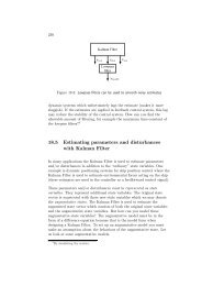
structure. As shown in Figure 2-11, the piping of the system is such that the output of<br />
Pump02 feeds Tank 1 and Tank 4 via Valve 1 (three-way valve). Similarly, output of Pump01<br />
feeds Tank 2 and Tank 3 via Valve 2 (three-way valve). The leakages from Tank 4 and Tank<br />
3 flow into Tank 2 and Tank 1 respectively. The levels of Tank 1 and tank 2 are measured by<br />
the level sensors mounted at the bottom of each tank but the levels of Tank 4 and Tank 3 are<br />
not measured.<br />
1 This surface is formed by the combination of the four tanks and the frame on which they are mounted.<br />
31
Figure 2-10: Four-tank laboratory process equipment<br />
2.8.1 System description<br />
The diagram depicted in Figure 2-11 shows diagrammatic representation of the four tank<br />
process and how it is connected to a computer via a DAQ 1 device.<br />
1 Data Acquisition<br />
32
Tank 3 Tank 4<br />
Three – way valve-2<br />
Three-way valve -1<br />
Level sensor-2<br />
Tank 1<br />
Tank 2<br />
Level sensor-1<br />
A/O<br />
A/I<br />
A/O<br />
A/O<br />
DAQ-2<br />
Pump 02<br />
Pump 01<br />
A/O A/I<br />
DAQ-1<br />
Bottom reservoir<br />
computer<br />
Figure 2-11: Diagrammatic representation of the four-tank process<br />
The components of the system are described as follows;<br />
2.8.1.1 Water reservoir<br />
The bottom reservoir is made out of aluminium (Al) which gives less weight to the structure<br />
as well as resistance to corrosion.<br />
2.8.1.2 Pumps<br />
Two 12 Volt DC Johnson impeller pumps are used in this process. They are labelled as Pump<br />
01 and Pump 02 as shown in Figure 2-11. They are located in a small pump room which is<br />
adjacent to the reservoir. The pumps are designed to operate within a voltage range of 0 to<br />
12V.<br />
Two amplifiers are used with the two pumps in order to convert the 0 to 5V electrical signal<br />
from the DAQ device to 0 to 12V that will be required to operate the pumps. A 15V power<br />
supply is used to supply power to the amplifiers.<br />
33
2.8.1.3 Valves<br />
Two Samson brand three-way valves are used for this system. They are labelled as three-way<br />
valve-1 and three-way valve-2 as illustrated in Figure 2-11. They are linearly operated valves<br />
and require a 0 to 5V control signal for operation and a 24 Volt AC electrical supply is used to<br />
power up the valves.<br />
2.8.1.4 Level sensors<br />
Two screw type pressure transmitters made from BD Sensors are used for this process and<br />
they are labelled as Level sensor-1 and Level sensor-2 as shown in Figure 2-11. Both are<br />
mounted at the bottom of the two lower tanks. The measurement range of these sensors are 0 -<br />
40 [mbar] corresponding to 0 - 400 [mmH 2 O], this is within acceptable accuracy limits of the<br />
process [21].<br />
The level sensors used for this process gives out a 4-20mA current signal. The voltage across<br />
the resistor varies from 2 – 6 [V], and so the voltage is scaled from 2 – 6 [V] to 0 – 20 [cm]<br />
representing the height of the tank [20]. The level sensors require a 12 – 36 [V] DC supply.<br />
The signal conditioning requirements of the sensors are;<br />
• 2 × 0 – 40 [mbar] pressure sensors that outputs 4 – 20 [mA] current signal<br />
• 2 × 500Ω resistor<br />
• 24 [V] DC supply<br />
The signal flow of the level sensors is shown in Figure 2-12<br />
Figure 2-12: Signal flow and scaling from sensor to LabVIEW application<br />
2.8.1.5 Data Acquisition<br />
Two NI USB-6008 DAQ devices from National Instruments are used in this process as shown<br />
in Figure 2-13. Each device is equipped with four differential analogue input channels and<br />
two differential analogue output channels, it is a 12-bit device and the sampling rate is 10 k<br />
samples/s.<br />
34
Figure 2-13: NI USB-6008 DAQ device from National Instruments<br />
2.8.2 Mathematical Model of the Four Tank Process<br />
The mathematical model for the four-tank process as deduced in [21] was derived by applying<br />
the mass balance and Bernoulli’s theorem to each tank. Then the model can be described as a<br />
non-linear differential equations as shown in equations (2-1), (2-2), (2-3) and (2-4).<br />
<br />
<br />
<br />
<br />
<br />
<br />
<br />
<br />
where:<br />
<br />
<br />
2 <br />
<br />
2 <br />
<br />
( 2-1)<br />
<br />
<br />
<br />
2 <br />
<br />
2 <br />
<br />
( 2-2)<br />
<br />
<br />
<br />
2 <br />
<br />
( 2-3)<br />
<br />
<br />
<br />
2 <br />
<br />
( 2-4)<br />
• A i - cross-sectional area of Tank i<br />
• a i - cross-sectional area of the outlet hole<br />
• h i - the water level in Tank i<br />
• v i - voltage applied to pump i<br />
• k i v i - flow from pump i<br />
• g - acceleration due to gravity<br />
• γ i – valve parameter for the valve i<br />
The equations (2-1), (2-2), (2-3) and (2-4) can be represented in the general form of a state<br />
space model as,<br />
35
( 2-5)<br />
( 2-6)<br />
Where x, y and u is the state vector, output vector and input vector respectively. The system<br />
has four (4) state variables h 1 , h 2 , h 3 and h 4 in the x vector, v 1 and v 2 are the two variables in<br />
the u vector , the y vector consists of h 1 and h 2 variables and then the A, B, C and D are<br />
matrices and D = 0 [21].<br />
The Taylor series is used around the four nominal values , <br />
, and in order to obtain<br />
a linear model.<br />
The system can be written as,<br />
<br />
<br />
0<br />
<br />
0<br />
<br />
<br />
<br />
0 <br />
0 <br />
<br />
<br />
<br />
<br />
0 0 <br />
0<br />
<br />
<br />
<br />
0 0 0 <br />
<br />
<br />
<br />
0<br />
0 <br />
<br />
0 <br />
<br />
<br />
<br />
<br />
<br />
<br />
( 2-7)<br />
<br />
<br />
0 <br />
0 0 0<br />
0 0 0 ( 2-8)<br />
( 2-9)<br />
( 2-10)<br />
According to [21], k c is taken as a calibration constant and chosen as 1 and the time constants<br />
for the tanks T i are given as<br />
<br />
<br />
<br />
for i = 1...4 ( 2-11)<br />
, ∈ 0,1 is determined from the valve setting before the start-up of an experiment for<br />
tanks 2 and 3 and corresponding tanks 1 and 4 respectively. The level sensors are calibrated<br />
considering k c = 1 as presented in [21].<br />
The overview of the states, parameters and nominal state values are shown in Table 2-1.<br />
Table 2-1: Overview of states, parameters and nominal values [21]<br />
Symbol State/ Parameter Values<br />
, , , Nominal levels 11.8, 12.5, 5.5, 9.5<br />
, <br />
<br />
Nominal pump settings 3.75, 3.7<br />
Area of the tanks 28<br />
36
Area of the drain in tank i 0.16, 0.13, 0.16, 0.13<br />
<br />
<br />
<br />
Ratio of the flows in the<br />
valves<br />
Pump proportionality<br />
constant<br />
0.4, 0.4<br />
0.67, 0.74<br />
<br />
Gravitational constant 981<br />
Time constant in the<br />
linearised model<br />
27.78, 35.56, 18.54, 30.94<br />
The overview of the controller is shown in Figure 2-14, the PID controller is used to control<br />
the process. A mathematical equation for a PID controller is shown in equation (2-12).<br />
<br />
<br />
<br />
<br />
<br />
<br />
<br />
( 2-12)<br />
Where u 0 is the nominal value for control variable, K p is the proportional gain, T i [s] is the<br />
integral time and T d [s] is the derivative time.<br />
Figure 2-14: Overview of the control system and the process<br />
The PID parameters for the two controllers were obtained as Kp1 = 0.9, Ti1 = 5, Kp2 = 0.8<br />
and Ti2 = 4.1 as presented in [21].<br />
37
2.9 Database systems<br />
A collection of (usually) organized information in a regular structure may be defined as a<br />
structured collection of records stored in a computer, so that an application can use it to<br />
answer queries [1]. Records are a collection of several data types with same type of<br />
information and an application used to manage and query database is called Database<br />
Management System (DBMS). The schema is a term which refers to structural description of<br />
type of data held in the database. The diagram in Figure 2-15 shows the structure of a<br />
database (data hierarchy).<br />
Figure 2-15: Data Hierarchy Schema, Records and data in a database [1]<br />
The Supervisory Control and Data Acquisition (SCADA) have a feature of collecting data<br />
amongst one of its numerous features, from RTUs, PACs, PLCs and a host of other field<br />
devices. A typical SCADA system has hundreds or thousands of interface points to the<br />
physical process. This makes it impossible to manage the information from each in the<br />
software module without a database. The diagram in Figure 2-16 shows a SCADA system<br />
with database. Time series database are used for runtime data/historical data, configuration<br />
database may be any database model and SQL database for the management system<br />
38
Figure 2-16: Example of SCADA system with database [1]<br />
The software systems consist of standard software modules, configuration tools for obtaining<br />
information for each point in the physical process and the configuration data. The<br />
configuration data are [22]<br />
• Parameters for all sensors and actuator (all input and output devices)<br />
• Parameters for computation of derived variable<br />
• Events definition and connection with control actions (if needed)<br />
• Controller parameter<br />
Configuration parameters are specific for each tag in the physical process and are required to<br />
be stored outside the software modules creating independency of the software module from<br />
the size of the physical plant. The configuration is saved in a database system so that the<br />
configuration tool and the software modules have access to the configuration data.<br />
The interface between the database system and the applications using the data base will<br />
include [1];<br />
1. Support for data input to the database system<br />
2. Support for data output from the database system<br />
3. Data representation<br />
4. Support for command input to the database system<br />
The diagram in Figure 2-17 shows a real time process database and applications for data<br />
access, The User interface has the command inputs from the operator (control purposes) and<br />
administrator (configuration) and the output connects to the presentation of process data in a<br />
format a user understands like display of dynamic attribute of tags and values (process<br />
variables). The Alarm log prints from the Alarm statistics. The application modules that<br />
interface the database with the plants are the sensor data input and filtering responsible for<br />
data acquisition and the actuator control interfaces the database with the output devices like<br />
pumps, valve, and motor among others.<br />
39
Digital regulator program contains controller algorithm for computation of control signals.<br />
The main parameters describing a point are listed as follows [22];<br />
• Code<br />
• Name/Description<br />
• Type<br />
• Address/Physical reference<br />
• Event class<br />
• Alarm class<br />
• Sampling time<br />
• Raw value<br />
• Converter value<br />
• Alarm state<br />
For analogue point these parameters are needed for conversion from raw values to<br />
engineering units<br />
• Scaling factor<br />
• Measuring units<br />
• Minimum and maximum values<br />
40
Figure 2-17: Diagram of real time database and applications for data access [22]<br />
41
PART II<br />
42
3 ANALYSIS OF SOFTWARE<br />
This section shows how the software was analysed in detail using the concepts of OOA.<br />
Proper analysis helps in outlining the scope of the software application and according to [23]<br />
poor scope definition is one of the main reasons why software projects fail. The overview of<br />
the analysis phase is shown in Figure 3-1.<br />
Figure 3-1: Analysis Phase of the SCADA software development [1]<br />
3.1 Requirements<br />
The requirements of the software were carried out by using FURPS+ and are outlined below;<br />
F Functionality<br />
1. The SCADA application should be module based and have a control (desktop)<br />
application (system) that will be hosted on a computer in the same location as the<br />
four-tank process, a configuration system that will be hosted on a web browser, and a<br />
monitoring system that will also be hosted on a web browser.<br />
2. The SCADA application should have the ability to monitor and control the four-tank<br />
process.<br />
• The client application should be able to read and write/save data to the<br />
database.<br />
• The control application should be able to read and write data to the four-tank<br />
process and read and write/save data to the database.<br />
3. The SCADA application should have an interactive user interface that is easy to<br />
understand with few color combinations.<br />
4. The control application should be developed using WPF and the client application<br />
should be developed using Silverlight.<br />
43
U Usability<br />
R Reliability<br />
• Having failover 1 capabilities.<br />
P Performance<br />
• Maximum of 0.2 seconds sampling time between the control application and the fourtank<br />
process.<br />
• Maximum of 2 seconds loop time between the control application and the database.<br />
• 24 × 7<br />
S Supportability<br />
• Windows OS with Silverlight<br />
+ Design Limitations<br />
3.2 Use cases<br />
The usecase defines what the system in its entirety shall do and it treats the system as a<br />
blackbox [23]. It shows the interactions between the actors and the system in order to<br />
accomplish a goal. The actors refer to those components that are external to the system but<br />
have certain roles that relate to the system [24].<br />
The usecase does not show how the system shall carry out the functions but on what the<br />
system will accomplish. The usecase is very important in defining the scope of the software<br />
application. The usecase diagram for the SCADA application is shown in Figure 3-2 and is<br />
explained as follows;<br />
SCADA server:<br />
All associations with the Operator and Admin actors go through the WAN. The Configuration<br />
and SQL usecases have no associations with the Operator actor. The SQL usecase have no<br />
association with the Operator and Admin actors. The Configuration usecase only informs<br />
(send trigger) the Control Algorithm usecase that some parameters have been changed in the<br />
database and that those parameters have to be updated in the Control Algorithm usecase.<br />
Control Application:<br />
The Control Pump, Control Algorithm, and Read Sensor usecases on the Control Application<br />
have no associations with the Operator and Admin actors as they only act as an interface to<br />
the pumps. The Control Algorithm and Read Sensor usecases have associations with the SQL<br />
usecase via the WAN.<br />
1 Ability to control the process by utilizing the configuration in a configuration back-up file when the WAN<br />
connection is broken.<br />
44
Control Application<br />
SCADA server<br />
System<br />
System<br />
Configuration<br />
Control Pump<br />
Database<br />
Admin<br />
Pumps<br />
Configuration file<br />
SQL<br />
Control Algorithm<br />
Alarm system<br />
Timer<br />
Timer2<br />
Monitoring<br />
Read Sensor<br />
Operator<br />
Sensors<br />
<strong>Report</strong>ing<br />
Printer<br />
Figure 3-2: Use case diagram of the SCADA system<br />
3.3 Domain model<br />
Based on [23], the domain model is static information of the domain entities that shows a<br />
representation of the real situation conceptual classes.<br />
It identifies the relationships among all the entities within the scope of the problem domain<br />
and commonly identifies their attributes [25]. The domain model for the SCADA application<br />
is shown in Figure 3-3.<br />
45
SCADA System<br />
SCADA Server<br />
Printer<br />
Control Application<br />
Disk<br />
SQL<br />
Configuration File<br />
WAN<br />
Timer2<br />
Timer<br />
DAQ<br />
Alarm System<br />
Sensor<br />
Pump<br />
Operator<br />
Admin<br />
Figure 3-3: Domain Model of the SCADA system<br />
3.4 Fully dressed use case document<br />
The FDUCD is a text document describing each of the usecases in detail showing how the<br />
software shall accomplish the specified functions. The FDUCD for the usecases are presented<br />
in appendix B2.<br />
3.5 System sequence diagram<br />
The SSD describes the dynamic functions of the system by showing the events that takes<br />
place from the system to the actors and vice versa as presented in [23].<br />
According to [23], the SSD describes what the system shall do and not how to do it. A SSD is<br />
developed for each usecase (see Figure 3-2) and it is based on the information in the FDUCD.<br />
The SSDs for the system is shown in appendix B1.<br />
3.6 Sequence diagram<br />
The sequence diagram shows the sequence of the messages between the objects (classes) as<br />
they occur with time. The sequence diagram for the system is shown in appendix B3. The<br />
sequence diagram is developed based on the information from the SSD and the domain model<br />
as shown in Figure 4-1.<br />
46
4 SYSTEM DESIGN<br />
4.1 Design of Software<br />
The interaction between the analysis and design phases of the SCADA application<br />
development is shown in Figure 4-1.<br />
Figure 4-1: Analysis and Design phases of the SCADA software development [1]<br />
4.2 Graphic Design of User Interface<br />
This section shows the graphic design adopted for the user interface of the various pages in<br />
the SCADA application which was developed using Microsoft Visio.<br />
4.2.1 Navigation chart<br />
The chart shows the sequence of the navigation from the main page to the various functional<br />
pages and vice versa in the SCADA application as shown in Figure 4-2.<br />
Figure 4-2: Chart showing the navigation flow<br />
47
4.2.2 Login page<br />
When the application is initialised, there will be a login prompt where the login details will be<br />
entered by the user (admin or operator) before gaining access see Figure 4-3.<br />
Figure 4-3: Design of the Login page of the SCADA application<br />
4.2.3 Main page<br />
After authentication from the login page, the system opens up the main page with various<br />
navigation buttons as shown in Figure 4-4.<br />
The admin user will have unlimited access to all parts of the application while for the<br />
operator, the configuration button will be disabled because the operator should only be able to<br />
adjust the setpoint reference and the valve which can be done from the monitoring page as<br />
shown in Figure 4-11.<br />
Figure 4-4: Design of the main page of the SCADA application<br />
48
4.2.4 Configuration page<br />
The configuration page is an environment where parameters related to the control application,<br />
data logging, alarm configuration and reporting can be configured as shown in Figure 4-5.<br />
Figure 4-5: Design of the configuration page of the SCADA application<br />
4.2.5 Alarm page<br />
The alarm page presents the list of all the active and acknowledged alarms as shown in Figure<br />
4-6. The page has an ’Acknowledge’ button that the operator uses to acknowledge an alarm<br />
by clicking it. The ’Acknowledge All’ button is used by the operator to acknowledge all the<br />
alarms that are displayed on the page. The design of the alarm page shown in Figure 4-6 is<br />
according to the standard presented in [1].<br />
49
Figure 4-6: Design of the alarm page of the SCADA application [1]<br />
4.2.6 Control application configuration page<br />
A child window is opened when the ‘Control application’ button is clicked which has a tab<br />
control that consists of configurable parameters related to the control application. This is the<br />
environment where the administrator can configure these parameters.<br />
The tab control consists of four tabs namely<br />
• Setpoint<br />
• Tank 1 control<br />
• Tank 2 control and<br />
• Timer<br />
as shown in Figure 4-7.<br />
50
Figure 4-7: Design of the control application configuration page of the SCADA application<br />
51
4.2.7 Configure alarm page<br />
A child window is opened when the ‘Configure Alarm’ button is clicked which presents an<br />
environment for the configuration of the High-High, High, Low, and Low-Low alarm limits<br />
as shown in Figure 4-8.<br />
Figure 4-8: Design of the configure alarm page of the SCADA application<br />
52
4.2.8 Configure report page<br />
When the ’Configure <strong>Report</strong>’ button is clicked, a child window is opened that presents<br />
options for the plant history data report and the alarm history data report. Individual tags can<br />
be selected for each of the options for the purpose of generating a report. Also, the desired<br />
duration of interest can also be configured (daily, weekly etc) in this page as shown in Figure<br />
4-9.<br />
Figure 4-9: Design of the configure report page of the SCADA system<br />
53
4.2.9 <strong>Report</strong> page<br />
When the ‘<strong>Report</strong>’ button is clicked on the main page a report page should be presented to the<br />
user that looks like what is shown in Figure 4-10. The page has options for the particular day,<br />
month, or year in which a report should be generated as well as a ‘Start’ and ‘End’ time<br />
option.<br />
Figure 4-10: Design of the report page of the SCADA system<br />
4.2.10 Monitoring page<br />
The monitoring page contains the information concerning the setpoint of tanks 1 and 2,<br />
controller output for pumps 01 and 02, level of tanks 1 and 2 etc. It also gives a dynamic<br />
representation of the four-tank process as shown in Figure 4-11.<br />
The monitoring page also has a section that shows the current active alarm, an alarm indicator<br />
and an ’Acknowledge Alarm’ button.<br />
The child window for the setpoint configuration pops up when the ‘Change setpoints’ button<br />
is clicked in order to change the setpoint for tanks 1 and 2. This is due to the fact that the<br />
54
access level only permits the operator to change the setpoint of the tank levels and valves,<br />
which was the motivation for the design of this option.<br />
Monitoring<br />
Alarm Status:<br />
No Alarm<br />
Acknowledge Alarm<br />
Main menu<br />
Tank 1<br />
Tank 2<br />
Configuration<br />
Valve 1 setpoint:<br />
Valve 2 setpoint:<br />
Alarm<br />
Tank 1 setpoint<br />
Tank 2 setpoint<br />
<strong>Report</strong><br />
Controller output 1:<br />
Tank 3 Tank 4<br />
valve 1 Valve 2<br />
Controller output 2:<br />
Tank 1 level:<br />
Tank 2 level:<br />
Tank 1 Tank 2<br />
Setpoint Configuration<br />
X<br />
Pump 01 Pump 02<br />
Tank 1 set point:<br />
Tank 2 set point:<br />
Change setpoints<br />
Valve 1 set point<br />
Valve 2 set point<br />
Save<br />
Close<br />
Figure 4-11: Design of the monitoring page of the SCADA system<br />
4.2.11 Control application<br />
The control application has an indicator named ‘Configuration data’ that shows where the<br />
configuration data was loaded (database or backup file) from. A child window is opened<br />
when the ‘Configuration’ button is clicked, this window will have the same design and<br />
functions as the child window in Figure 4-7. The application has one button for starting the<br />
control application, and one for stopping the control application. A status window named<br />
‘Control application status’ will show the current state and errors. The monitoring part will be<br />
55
of the same design as the monitoring page. The design of the control application is shown in<br />
Figure 4-12.<br />
Configuration data:<br />
Configuration<br />
Tank 1<br />
Valve 1 setpoint:<br />
Tank 1 setpoint<br />
Tank 2<br />
Valve 2 setpoint:<br />
Tank 2 setpoint<br />
Start<br />
Stop<br />
Controller output 1:<br />
Tank 3 Tank 4<br />
valve 1 Valve 2<br />
Controller output 2:<br />
Control application status:<br />
Tank 1 level:<br />
Tank 2 level:<br />
Tank 1 Tank 2<br />
Pump 01 Pump 02<br />
Figure 4-12 Design of the control application<br />
4.3 Design of database model<br />
A relational database model was adopted and was designed using Microsoft Visio as shown in<br />
Figure 4-13. It can be seen that the TagId and TaskId are foreign keys in the TagTask table<br />
since the TagTask table links the Tag and Task tables. Also, the ControllerId and TagId are<br />
foreign keys in the TagController table since the TagController table links the Tag and<br />
Controller tables.<br />
According to [26] and [27], the primary key uniquely identifies each record in the table while<br />
the foreign key is a field in a relational table that matches the primary key column of another<br />
table and is used to cross-reference tables.<br />
56
Figure 4-13: Database model adopted for the SCADA system<br />
57
5 IMPLEMENTATION OF SOFTWARE<br />
This section shows the parts of the design that were implemented in the prototype along with<br />
the assumptions. The alarm, report and data logging parts of the SCADA application were not<br />
implemented in the prototype.<br />
5.1 Control application<br />
In this section, the implementation of the control application will be explained. There is some<br />
simplified code examples through this section that will help the reader understand the<br />
methods that were used while coding the application. For the full code solution, please see the<br />
Microsoft Visual Studio project file for the control application located on the CD in Appendix<br />
D (the project name is DAQcontrolApp).<br />
5.1.1 Configuration files<br />
The control application uses two external files called DAQcontrolApp.exe.config and<br />
ConfigBackup.txt. The DAQcontrolApp.exe.config file contains the database connection<br />
string, views and stored procedures used in the SCADA system. The reason why this was<br />
done is to allow the SQL configuration to be changed without recompiling the application<br />
project. The content of this file is shown in Figure 5-1.<br />
Figure 5-1: The SQL configuration file DAQcontrolApp.exe.config content.<br />
The ConfigBackup.txt file contains the latest configuration data that was received by the<br />
control application. The idea behind this backup file is that if the database is unavailable, the<br />
control application can still be started and run. The content of this file is shown in Figure 5-2.<br />
58
Figure 5-2: The configuration backup file ConfigBackup.txt content.<br />
The following C# code example shows how the database connection string is read from the<br />
DAQcontrolApp.exe.config file that is placed in the same folder as the application:<br />
SQLconfig[0] = ConfigurationManager.AppSettings["DBconnStr"];<br />
The following C# code example shows how to read and write to the ConfigBackup.txt file<br />
that is placed in the same folder as the application:<br />
First we get the application location:<br />
string AppLocation =<br />
System.IO.Path.GetDirectoryName(Assembly.GetExecutingAssembly().Location);<br />
To ‘read’, the following code was used :<br />
config = System.IO.File.ReadAllLines(AppLocation + @"\ConfigBackup.txt");<br />
To ‘write’, the following code was used:<br />
System.IO.File.WriteAllLines((AppLocation + @"\ConfigBackup.txt"), *input array*);<br />
where the *input array* is an array containing all the different values that will be written to<br />
the file.<br />
5.1.2 Initialization<br />
When the control application is opened an initialization will start, first the database<br />
connection information is loaded from the .config file (DAQcontrolApp.exe.config) into the<br />
application. Then the application will try to connect to the database and retrieve the<br />
configuration values, if connection attempt fails the application will load the configuration<br />
from a backup file (ConfigBackup.txt). This operation is done by using a try-catch statement;<br />
if the try block creates an exception (connection to database fails) the code in the catch block<br />
will be executed. An example of a try-catch statement in C# is shown below:<br />
59
try<br />
{<br />
}<br />
catch<br />
{<br />
}<br />
//Try connecting to the database and load configuration.<br />
//Try block creates an exception during execution (database connection<br />
fails), load configuration from backup file.<br />
The control application configuration and backup file will automatically be updated when the<br />
configuration values are changed in the database. A trigger (appendix C) in the database will<br />
detect an update change in one of the configuration tables, this trigger will then set a related<br />
flag value (in database flag table) to 1. This flag is sent to the application each time the<br />
application updates the tag values in the database, if the flag is equal to 1 the control<br />
application will retrieve the new configuration and update the backup file. The control<br />
application will show where the configuration data was loaded from (database or backup file).<br />
When the configuration is loaded, the DAQ outputs will be initialized such that valves go to<br />
the positions defined in the configuration, and the pump outputs are set to 0V. Now if the<br />
configuration is successfully loaded and both DAQ’s are connected the start button will be<br />
enabled so the control application can be started, this is shown in Figure 5-3.<br />
Figure 5-3: The control application UI when initialized and ready to run.<br />
If the control application fails to load the configuration or the DAQ’s are not connected to the<br />
computer, the start button will not be enabled and an error message will appear in the status<br />
field (lower-left corner), this is shown in Figure 5-4.<br />
60
Figure 5-4: The control application UI if the DAQ connection fails.<br />
5.1.3 Database communication<br />
An own class (DBconnection) in control application has been created to handle the database<br />
communication (both read and write). In order to communicate with the database, a<br />
connection is opened with a connection string:<br />
Server=tcp:JINX\SQLEXPRESS,1433;Database=SCADA;User Id=sa;Password=Neverhood<br />
In this string, a connection to a database called SCADA is established on a computer named<br />
JINX through TCP port 1433 (instance name is SQLEXPRESS). The database user id is sa and<br />
the password is Neverhood. When the connection is established the query command can be<br />
executed, after the database response is saved to a data set the database connection should be<br />
closed (asynchronous query). A C# code example on how this works is shown below:<br />
conn = new SqlConnection(*Connection string*);<br />
conn.Open();<br />
SqlCommand command = new SqlCommand(*query command*, conn);<br />
SqlDataAdapter adapter = new SqlDataAdapter(command);<br />
DataSet DatabaseResponse = new DataSet();<br />
adapter.Fill(DatabaseResponse);<br />
conn.Close();<br />
5.1.4 DAQ communication<br />
In order to communicate with a DAQ (Data Acquisition) from NI (National Instruments), four<br />
assembly files needs to be added to the control application (we only need to add two<br />
references, the dll files are automatically added to the compiled solution), all of these files are<br />
provided by NI and are called:<br />
• NationalInstruments.Common<br />
• NationalInstruments.Common.dll<br />
61
• NationalInstruments.DAQmx<br />
• NationalInstruments.DAQmx.dll<br />
These assembly files did not have support for Silverlight 4 during the project, so a WPF<br />
(Windows Presentation Foundation) application was created instead. WPF applications are<br />
similar to Silverlight applications as both uses XAML and .NET programming languages (C#,<br />
VB etc.).<br />
The DAQ tasks that are used must also be present at the computer that runs the control<br />
application. These tasks can either be imported to a computer with MAX (Measurement &<br />
Automation Explorer) from NI through a task configuration file (.nce), or created with MAX.<br />
The task configuration file for this project is included for easy deployment (for more<br />
information, please see section 6.2).<br />
In the control application, there are four tasks that must be present see Table 5-1:<br />
Table 5-1: DAQ task descriptions<br />
Task name:<br />
SCADAinput1<br />
SCADAinput2<br />
SCADAoutput1<br />
SCADAoutput2<br />
Description:<br />
Read data from DAQ 1 input, this is the<br />
sensor data for tank 1. The input range is<br />
from 2V to 6V.<br />
Read data from DAQ 2 input, this is the<br />
sensor data for tank 2. The input range is<br />
from 2V to 6V.<br />
Write data to DAQ 1 outputs, these are the<br />
pump 1 and valve 1 control signals. The<br />
output range is from 0V to 5V.<br />
Write data to DAQ 2 outputs, these are the<br />
pump 2 and valve 2 control signals. The<br />
output range is from 0V to 5V.<br />
All of the tasks have Sample on demand as acquisition method. In the control application, two<br />
classes have been created to handle the DAQ communication for reading (DAQReadSensor)<br />
and writing (DAQWriteOutput) to the two DAQs used in the four tank process.<br />
To read a single channel, the C# code (s_value is the sensor value) example below can be<br />
used:<br />
using (Task AnalogRead = DaqSystem.Local.LoadTask(*task name*))<br />
{<br />
AnalogSingleChannelReader reader = new AnalogSingleChannelReader(AnalogRead.Stream);<br />
s_value = reader.ReadSingleSample();<br />
62
}<br />
To write to multiple channels, the C# code example below can be used:<br />
using (Task AnalogWrite = DaqSystem.Local.LoadTask(*task name*))<br />
{<br />
AnalogMultiChannelWriter writer = new AnalogMultiChannelWriter(AnalogWrite.Stream);<br />
writer.WriteSingleSample(true, *output array*);<br />
}<br />
When reading the sensors, the DAQ input needs to be converted before the values can be<br />
used. The 2 - 6 [V] input must be converted into 0 - 20 [cm] (tank height). This is done by the<br />
simple calculation below:<br />
Converted sensor value = (5 * sensor value) – 10<br />
When converting from 0 - 20 [cm] to 0 – 5 [V], only dividing by 4 is required (multiply by 4<br />
when going from volt to cm).<br />
5.1.5 Starting the control application<br />
When the control application is initialized (without errors), the application can be started by<br />
clicking the enabled ‘start’ button on the left side of the UI (User Interface), shown in Figure<br />
5-3.<br />
When the start button is clicked the control application will initialize the control algorithm<br />
class (ControlAlgorithm) with the configuration values needed and start two timers named t1<br />
(ControlTimer1) and t2 (ControlTimer2). A message confirming that the application is<br />
running will be shown in the status field, the stop button will be enabled and the start button<br />
will be disabled, this is shown in Figure 5-5.<br />
63
Figure 5-5: Running control application.<br />
With timers, events (containing a piece of code) are triggered that are repeated after a given<br />
time. In the control application t1 triggers (Tick) each 100 ms and t2 triggers (Tick2) each<br />
second (1000ms).<br />
C# code example on how to create and start a timer:<br />
DispatcherTimer t1 = new System.Windows.Threading.DispatcherTimer();<br />
t1.Tick += new EventHandler(Tick);<br />
T1.Interval = new TimeSpan(*days*, *h*, *min*, *s*,*ms*));<br />
T1.Start();<br />
In timer t1 the control application reads the DAQ input (sensor values), calculate the new<br />
controller output, write to the DAQ outputs (pumps and valves) and update the UI. In timer t2<br />
the control application will update the database with new tag values.<br />
The code that t1 triggers (Tick1) can be seen below:<br />
private void Tick(object sender, EventArgs e)<br />
{<br />
//Read sensor values<br />
SensorValues = Read.ReadSensor();<br />
//Calculate PI-controller output.<br />
ControlOutput = CA.CalculateOutput(Configuration[10], Configuration[11],<br />
SensorValues);<br />
//Write values to DAQ outputs.<br />
Write.WriteOutput(ControlOutput, Configuration[12], Configuration[13]);<br />
}<br />
//Update UI with new sensor values<br />
CAout1.Text = Convert.ToString(ControlOutput[0]);<br />
CAout2.Text = Convert.ToString(ControlOutput[1]);<br />
SensorValue1.Text = SensorValues[0];<br />
SensorValue2.Text = SensorValues[1];<br />
Tank1.Value = 5 * Convert.ToDouble(SensorValues[0]);<br />
Tank2.Value = 5 * Convert.ToDouble(SensorValues[1]);<br />
64
The code that t2 triggers (Tick2) can be seen below:<br />
private void Tick2(object sender, EventArgs e)<br />
{<br />
string[] TagValues = new string[6];<br />
//Update the array that containing the newest tag values.<br />
TagValues[0] = Configuration[12];<br />
TagValues[1] = Configuration[13];<br />
TagValues[2] = Convert.ToString(ControlOutput[0]);<br />
TagValues[3] = Convert.ToString(ControlOutput[1]);<br />
TagValues[4] = SensorValues[0];<br />
TagValues[5] = SensorValues[1];<br />
//Update database with the newest tag values and get UpdateFlag value.<br />
try<br />
{<br />
UpdateFlag = DB.DBwrite(TagValues);<br />
}<br />
catch<br />
{<br />
}<br />
ControlAppStatus.Text = "ERROR: Cant write to the database.";<br />
}<br />
//Update configuration if UpdateFlag is true.<br />
if (UpdateFlag == true)<br />
{<br />
Configuration = InitializeConfig();<br />
UpdateFlag = false;<br />
}<br />
5.1.6 Control algorithm<br />
In the control application, a class (ControlAlgorithm) have been created to calculate the DAQ<br />
outputs that controls pumps 1 and 2. This class contains a control algorithm used to control<br />
the water level in tanks 1 and 2 (the algorithm is a PI-controller). The controller setpoints are<br />
given from 0 to 20 cm (height of tanks 1 and 2).<br />
The control algorithm that was used can be seen in equations (5-1), (5-2) and (5-3):<br />
( 5-1)<br />
∗ ( 5-2)<br />
∗ / ∗ ( 5-3)<br />
where<br />
e - is the difference (error) between the setpoint reference and process measurement<br />
(controller input).<br />
r - is the setpoint reference.<br />
y - is the process measurement (sensor values).<br />
u - is the controller output (pump outputs).<br />
Kp - is the proportional gain for the PI-controller.<br />
65
Ti - is the integral time for the PI-controller.<br />
dt - is the sampling time of the application in seconds (default 0.1 [s])<br />
A fail-safe has been implemented to prevent the controller output from exceeding the DAQ<br />
output range. This is done after the controller output has been converted from cm to V.<br />
5.1.7 Control configuration<br />
The controller configuration can be changed inside the control application; this is done by<br />
clicking on the configuration button found on the left side in the UI see Figure 5-3. When this<br />
is done a child window appears, in this window the user can see the current controller<br />
configuration and will be able to make changes to it. When the changes are finished, click the<br />
‘Save’ button in order to store the new configuration in the database (and backup file), if the<br />
‘Close’ button is clicked, the changes will not be saved and will be discarded and the window<br />
will be closed. The Child window with the different tabs is shown in Figure 5-6.<br />
66
Figure 5-6: Controller configuration child window with the different tabs.<br />
5.1.8 Stopping the control application<br />
In order to stop the control application properly, a shutdown procedure have been created.<br />
When the stop button is clicked:<br />
• Both timer t1 and t2 will stop.<br />
• The DAQ pump outputs will be set to 0.<br />
• Status field is updated confirming that the control application is stopped.<br />
• UpdateFlag is set to false.<br />
• Water level in tank 1 and 2 in the UI will be set to zero.<br />
• Start button enabled and Stop button disabled.<br />
67
5.2 Silverlight application<br />
In this chapter the implementation of the Silverlight application will be explained. There is<br />
some simplified code examples through this section that will help the reader understand the<br />
methods that were used while coding the application. For the full code solution, please see the<br />
Microsoft Visual Studio project file for the Silverlight application located on the CD in<br />
Appendix D (the project name is SCADAapp).<br />
5.2.1 WCF service<br />
Windows Communication Foundation (WCF) is a framework for building service-oriented<br />
applications as presented in [17]. If a database is to be accessed with the Silverlight<br />
application, a WCF service that handles the communication needs to be created (the WCF<br />
service will be placed on the .Web part of the Silverlight project).<br />
The Silverlight application that is created have three WCF services, one for reading from the<br />
database, one for writing to the database and one for checking the username and password<br />
when a user logs in. The C# code behind the database communication is of the same method<br />
as the one used in the control application (see section 5.1.3 for more details).<br />
The read service can return 2 different arrays depending on what read option that was chosen,<br />
the options are shown in Table 5-2. The write service only contains one option (write option<br />
0), and this option will write the given configuration (array) to the database.<br />
Table 5-2: WCF read service options<br />
Read option:<br />
Description:<br />
0 Returns the controller configuration.<br />
1 Returns the values used in the monitoring<br />
page (valves, pumps, sensors and setpoints).<br />
When the service references (read and write) are added to the project part of the Silverlight<br />
application, the WCF services can then be called. The C# code below shows how the<br />
Silverlight application calls the read WCF service to get the configuration (read option 0):<br />
int ReadOption = 0;<br />
ReadServiceClient rclient = new ReadServiceClient();<br />
rclient.ReadDatabaseCompleted += new<br />
EventHandler(client_ReadDatabaseCompleted);<br />
rclient.ReadDatabaseAsync(ReadOption);<br />
void client_ReadDatabaseCompleted(object sender, ReadDatabaseCompletedEventArgs e)<br />
{<br />
68
}<br />
Configuration = e.Result.ToArray();<br />
The SQL configuration required for database communication (same as in the control<br />
application) is located in the Web.config file (this file already existed in the .Web part of the<br />
Silverlight application; see section 6.3 for more information).<br />
5.2.2 Login Page<br />
In the login page the user will be able to log into a personal account (own username and<br />
password), the two different types of accounts are Administrator and Operator. The<br />
Administrator account type has access to everything (Figure 5-9), while the Operator account<br />
type does not have access to the configuration page (Figure 5-10). To proceed to the main<br />
page of the SCADA system, a valid username and password must be entered before clicking<br />
the login button, the UI is shown in Figure 5-7. The default usernames and passwords have<br />
been set to be the same as the user account type (User: Administrator, Password:<br />
Administrator).<br />
Figure 5-7: Login page for the Silverlight application.<br />
The Silverlight application will use the WCF login service to check the entered username and<br />
password against the username and password list in the database. If the wrong username or<br />
password is entered a message will appear stating that the username or password is wrong,<br />
shown in Figure 5-8. If the right password is entered the user will be navigated to the main<br />
page and the navigation buttons will be enabled depending on the account type.<br />
69
Figure 5-8: Login page if login fails (wrong username or password).<br />
Figure 5-9: Main SCADA page when login is successful as Administrator.<br />
5.2.3 Main Page<br />
After the login, the user will be navigated to the SCADA main page. Depending on the<br />
account type, different buttons will be unlocked. The C# code below shows how the buttons<br />
are unlocked:<br />
private void LoginLevel()<br />
{<br />
if (UserLevel == "Administrator")<br />
{<br />
monitoringButton.IsEnabled = true;<br />
ConfigButton.IsEnabled = true;<br />
<strong>Report</strong>ingButton.IsEnabled = true;<br />
AlarmButton.IsEnabled = true;<br />
}<br />
}<br />
if (UserLevel == "Operator")<br />
{<br />
monitoringButton.IsEnabled = true;<br />
<strong>Report</strong>ingButton.IsEnabled = true;<br />
AlarmButton.IsEnabled = true;<br />
}<br />
70
The UserLevel variable is provided from the login page. If the Administrator account is used,<br />
the main page will be as shown in Figure 5-9, if the Operator account is used, the main page<br />
will be as shown in Figure 5-10.<br />
Figure 5-10: Main SCADA page when login is successful as Operator.<br />
The C# code below shows how the application navigates to the monitoring page when the<br />
‘Monitoring’ button is clicked, the user level is provided to unlock the configuration button (if<br />
administrator) on the quick navigation menu.<br />
private void monitoringButton_Click(object sender, RoutedEventArgs e)<br />
{<br />
this.Content = new Monitoring(UserLevel);<br />
}<br />
5.2.4 Monitoring page<br />
When the Monitoring page is opened (see Figure 5-11), it will initialize and start timer t<br />
(triggers every 2 seconds). Timer t (Tick) is of the same type as the one used in the control<br />
application (see section 5.1.5 for details). This timer will use the WCF read service (with read<br />
option 1) to get the newest tag and setpoint values from the database, when the values are<br />
received the UI is updated, the code is shown below:<br />
private void Tick(object sender, EventArgs e)<br />
{<br />
ReadServiceClient client = new ReadServiceClient();<br />
client.ReadDatabaseCompleted += new<br />
EventHandler(client_GetTagsCompleted);<br />
int ReadOption = 1; //To read the monitoring values: ReadOption = 1<br />
client.ReadDatabaseAsync(ReadOption);<br />
}<br />
void client_GetTagsCompleted(object sender, ReadDatabaseCompletedEventArgs e)<br />
{<br />
TagValues = e.Result.ToArray();<br />
//Update Monitoring display.<br />
Valve1.Text = TagValues[0];<br />
Valve2.Text = TagValues[1];<br />
71
Pump1.Text = TagValues[2];<br />
Pump2.Text = TagValues[3];<br />
Sensor1.Text = TagValues[4];<br />
Sensor2.Text = TagValues[5];<br />
Setpoint1.Text = TagValues[6];<br />
Setpoint2.Text = TagValues[7];<br />
}<br />
progressBar1.Value = 5 * Convert.ToDouble(TagValues[4]);<br />
progressBar2.Value = 5 * Convert.ToDouble(TagValues[5]);<br />
Figure 5-11: Monitoring page for the SCADA system.<br />
The tank and valve setpoints can be changed from the monitoring page, to do this click the<br />
‘Change setpoints’ button at the bottom of the monitoring page (see Figure 5-11). This will<br />
bring up a child window (see Figure 5-12) that allows the user to change the setpoints, C#<br />
code shown below:<br />
private void SetpointConfig_Click(object sender, RoutedEventArgs e)<br />
{<br />
SetpointConfig SetpointConfiguration = new SetpointConfig();<br />
SetpointConfiguration.Show();<br />
}<br />
72
Figure 5-12: Setpoint configuration child window.<br />
In the child window the user can see the current setpoint values and change it. When the<br />
changes are finished click the ‘Save’ button in order to store the new setpoints to the database,<br />
if the ‘Close’ button is clicked, the changes are not saved and will be discarded and the<br />
window will be closed.<br />
5.2.5 Configuration page<br />
From the configuration page (see Figure 5-13), all of the configuration values for the SCADA<br />
system can be changed. For the implemented prototype, only the ‘Control application’<br />
configuration page can be opened.<br />
Figure 5-13: Configuration page of the SCADA system.<br />
When the ‘Control application’ button is clicked a child window appears (see Figure 5-14), in<br />
this window the user can see the current controller configuration and change it. When the<br />
changes are finished click the ‘Save’ button in order to store the new configuration in the<br />
73
database, if the ‘Close’ button is clicked, the changes are not saved and will be discarded and<br />
the window will be closed. The Child window has the same UI as in the configuration page in<br />
the control application; therefore see Figure 5-6 for all the different tabs.<br />
Figure 5-14 : Control configuration child window in the Silverlight application.<br />
5.3 Database implementation using MS SQL server<br />
2008<br />
The database model was implemented in MS SQL. A holistic approach was adopted in the<br />
database implementation by creating the SCADA database, creating the tables, inserting<br />
default values into the tables, creating stored procedures, creating views and creating triggers<br />
all in one SQL script. The complete SQL script can be found in appendix C of this report.<br />
5.4 Testing<br />
The test procedure presented in [1] was adopted for the system and is as follows<br />
• Unit test<br />
• Integration test<br />
• System test<br />
From the design of the system, it had been subdivided into three modules namely; the<br />
• Control application (WPF)<br />
• Database<br />
• Client application (Silverlight)<br />
74
5.4.1 Unit Test<br />
The unit tests were carried out on each of the modules and the procedure used for carrying out<br />
the tests is represented in the flowchart shown in Figure 5-15.<br />
Implementation<br />
Test for<br />
functionality<br />
Test OK<br />
No<br />
Yes<br />
5.4.1.1 Control application test<br />
Ready for<br />
Integration<br />
Figure 5-15: Unit test procedure for SCADA system<br />
For the control application, three usecases were present (see Figure 3-2) and the tests were<br />
carried out based on the functionality of the application like reading values from the process,<br />
regulating the pumps, computation of control output based on the programmed algorithm etc.<br />
5.4.1.2 Database test<br />
The database script had the ability of creating the database, creating the tables, inserting<br />
default values into the tables, creating stored procedures, creating views and creating triggers<br />
in one execution and each of these functions were tested.<br />
5.4.1.3 Client application test<br />
The GUI of the client application was tested based on the design that was adopted such as the<br />
colours, the type of tank, the dynamic properties etc.<br />
Also, since one of the main advantages of Silverlight applications is their dynamic resizing<br />
property, hence the client application was tested to see if the dynamic resizing was achieved.<br />
75
5.4.2 Integration test<br />
The integration test was carried out on each of the subsystems i.e.<br />
• Interaction between the control application and the database<br />
• Interaction between the client application and the database<br />
The procedure used for the test is represented in the flowchart shown in Figure 5-16.<br />
Implementation<br />
Test for<br />
functionality/<br />
interaction between<br />
applications<br />
Test OK<br />
No<br />
Yes<br />
Ready for<br />
Integration<br />
Figure 5-16: Integration test procedure for SCADA system<br />
5.4.2.1 Control application and database<br />
Tests were carried out to see if data was being ‘read from’ and ‘written to’ the database from<br />
the control application. Also, the tests were carried out to see if the data were being written to<br />
the correct tables in the database.<br />
5.4.2.2 Client application and database<br />
Tests were carried to see if data was being ‘read from’ and ‘written to’ the database from the<br />
client application. Also, the tests were carried out to see if the data were being written to the<br />
76
correct tables in the database. Tests were carried out to see if the setpoint values 1 were<br />
updated after they were changed 2 .<br />
5.4.3 System test<br />
The entire system was now tested from the client application to the four-tank process to see if<br />
the requirements were fulfilled. The setpoints of the two tanks were changed from the client<br />
application and the changes were effected in the four-tank process. The levels of the two tanks<br />
could be monitored from the client application dynamically.<br />
Implementation<br />
System Test<br />
Test OK<br />
No<br />
Yes<br />
Ready for<br />
Deployment<br />
Figure 5-17: System test procedure for SCADA system<br />
1 The display of the setpoint values for the two tanks on the monitoring page were programmed to be read-only.<br />
In order to change the setpoint the ‘Change setpoints’ button has to be clicked to open a child window where the<br />
setpoints can then be changed.<br />
2 The changes were effected in the database and the monitoring page was checked to see if the setpoint values<br />
were updated and vice versa.<br />
77
PART III<br />
78
6 DEPLOYMENT<br />
This section gives an overview of the SCADA application interaction with the four-tank<br />
process, how the SCADA application and the database were hosted on the server. The<br />
overview of the entire system is shown in Figure 6-1.<br />
Figure 6-1: Overview of SCADA system<br />
6.1 Database deployment<br />
For easy deployment, an SQL script has been created for MS SQL, this script will:<br />
• Create a database named SCADA.<br />
• Create all database tables.<br />
• Initialize the tables with default values.<br />
• Create the database procedures used.<br />
• Create database views.<br />
79
• Create database trigger.<br />
Just run the “SCADA database.sql” file (located in the Deployment folder on the CD in<br />
Appendix D) and execute the query inside MS SQL, note: If a database called SCADA<br />
already exist, the user need to change the database name at the top of the script. The complete<br />
database script is shown in appendix C. Comments have been used in the script to explain the<br />
code so the user can understand the structure of the code.<br />
The TCP port 1433 (database) and UDP port 1434 (SQLServerBrowser) should be opened in<br />
the firewall on the computer hosting the database (to allow communication). The TCP port<br />
used must also be defined in the SQL server Configuration Manager.<br />
6.2 Control application deployment (WPF)<br />
The control application can be executed from any location on the computer, the seven files<br />
that are needed, must to be in the same folder. The Control Application subfolder is located in<br />
the Deployment folder on the CD in Appendix D.<br />
To change the database connection string, simply open the DAQcontrolApp.exe.config file<br />
and change the line marked as connection string (this is important to change, the default<br />
computer is JINX).<br />
The DAQ tasks that are needed can be imported into MAX through an NI Configuration<br />
Export file that was created for the deployment, this file is named SCADA_Task_Data.nce,<br />
and is located in the Deployment folder on the CD in Appendix D. When importing the tasks<br />
in MAX, you must select which DAQ devices to use (marked on the four tank process). DAQ<br />
number 1 on the process should be selected as SCADA1 and DAQ number 2 as SCADA2.<br />
6.3 Client application deployment (Silverlight)<br />
The hosting of the Silverlight application was done with IIS (Internet Information Service)<br />
7.5. For easy deployment the folder to be published in IIS is provided (located in the<br />
Deployment folder on CD in Appendix D), but in order to get it to work two things must be<br />
done:<br />
1. The SQL database string must be updated for the correct database used.<br />
2. The WCF service references must be updated in the Silverlight application so they<br />
have the right URL address.<br />
To update the SQL connection string, open the Web.config file located in the<br />
*SCADA site root*\SCADAapp\ and change the line marked as connection string.<br />
80
There are two different ways of updating the WCF service references, either by updating the<br />
URL for the service references in MS Visual Studio (right click and select update service<br />
reference in the solution explorer), or by opening the ServiceReferences.ClientConfig file<br />
inside the SCADAapp.xap file and making changes to the URL manually.<br />
If MS Visual Studio is used, open the project file and re-compile the entire application to<br />
update the references, it’s the easiest way if the user don’t know much about how the<br />
ServiceReferences.ClientConfig file works.<br />
If the SCADAapp.xap (works like a .zip file) file is opened and the URL references in<br />
ServiceReferences.ClientConfig are edited, the entire project file is not needed neither is recompilation<br />
necessary. Just add the folder into IIS after the modifications and the SCADA<br />
application should be hosted.<br />
81
7 CONCLUSION AND RECOMMENDATIONS<br />
The development of a prototype of the SCADA system for the four-tank laboratory process<br />
was carried out successfully. WPF, SQL and Silverlight 4 together with C# programming<br />
language were used in the implementation of the prototype. A relational database (SQL<br />
server) was used instead of a real-time database due to the limited resources available.<br />
Learning Silverlight 4 was a challenge considering the time constraint (about 3 months) and<br />
implementing it in a real process within the allotted time frame. However, the comprehensive<br />
effort of the team comprising six group members along with the wonderful supervision by the<br />
supervisor made this a reality.<br />
At the initial phase of the project the literature study, analysis and design of the software and<br />
learning of Silverlight 4 were carried out. The examples provided by the Microsoft’s MSDN<br />
web site were very helpful in learning Silverlight 4. Then at the concluding phase of the<br />
project the following were accomplished<br />
• Control application implementation<br />
• Client (web) application implementation<br />
• Database communication with the control application<br />
• Communication between the client and database<br />
• Deployment of the application<br />
The alarm monitoring page in client application was designed using current standards being<br />
used in the industry [1]. The monitoring page for the process was designed to be as simple as<br />
possible since it is for a laboratory process. The client application was hosted using IIS and a<br />
user guide was added to complete the deployment process.<br />
However, it is important to note that the valve must be fully opened (considering the fact that<br />
it is a three-way valve) for stable operation of the system due to the fact only the two lower<br />
tanks were considered for the control strategy implemented.<br />
Therefore, it can be inferred that the work done on the project is a good gateway towards<br />
implementing a complete SCADA solution using one of the latest software (Silverlight 4)<br />
available.<br />
Some of the recommendations that are being proposed for future work in this area are as<br />
follows<br />
• The use of a real-time database for the SCADA system.<br />
• Scalability by adding tags, controllers, DAQs, valves, sensors, pumps without<br />
modifying the program.<br />
• Implementation of advanced estimation and control algorithms for better control of the<br />
levels of all four tanks considering the fact that it is a MIMO system.<br />
• Improvements to the data entry operations.<br />
• Implementing the OPC protocol and integrating it to this system.<br />
82
• Introducing students to the proposed program to be used for developing an application<br />
early enough.<br />
83
REFERENCES<br />
[1] N.-O. Skeie. (2010). Industrial Information Technology, Lecture notes for Computer<br />
Devices, Data Communication, Field Bus, OPC, Process Database, Embedded<br />
systems, Mechatronics, Real-time systems, Alarm System, EEx, Testing and Data<br />
Recovery (0.6 ed.).<br />
[2] H.-P. Halvorsen. (2010). OPC and Real-Time Systems in LabVIEW.<br />
[3] A. Daneels and W. Salter, "WHAT IS SCADA," presented at the International<br />
Conference on Accelerator and Large Experimental Physics Control Systems, Trieste,<br />
Italy, 1999.<br />
[4] http://en.wikipedia.org/wiki/Scalability. (2010, 25th November). Scalability.<br />
[5] http://en.wikipedia.org/wiki/Redundancy_(engineering). (2010, 25th November).<br />
Redundancy (engineering).<br />
[6] www.ehow.com. (2010, 11th October). Types of Scada Systems.<br />
[7] www.wonderware.com. (2010, 18th October). SCADA systems.<br />
[8] YA711, "Principles for alarm system design (ya-711), Technical report, Norwegian<br />
Petroleum Directorate," ed, 2001.<br />
[9] R. Lair, Beginning Silverlight 4 in C#: Robert Lair, 2010.<br />
[10] A. Ghoda. (2010). Introducing Silverlight 4<br />
[11] http://en.wikipedia.org/wiki/Silverlight. (2010, 25th November). Microsoft Silverlight.<br />
[12] http://en.wikipedia.org/wiki/Windows_Presentation_Foundation. (2010, 24th<br />
November). Windows Presentation Foundation.<br />
[13] B. Sempf, et al., C# 2010 All-in-One for Dummies Wiley Publishing, Inc., 2010.<br />
[14] http://archive.devx.com/dotnet/articles/cp0901/cp0901-1/waws.asp. (2010, 24th<br />
November). What Are Web Services .<br />
[15] http://en.wikipedia.org/wiki/Web_Services. (2010, 24th November). Web service.<br />
[16] http://no.wikipedia.org/wiki/ASP.NET. (2010, 24th November). ASP.NET.<br />
[17] http://msdn.microsoft.com/en-us/library/ms731082.aspx. (2010, 24th November).<br />
What Is Windows Communication Foundation.<br />
[18] http://en.wikipedia.org/wiki/Windows_Communication_Foundation. (2010, 24th<br />
November). Windows Communication Foundation.<br />
[19] P. Brown, Silverlight 4 in Action Manning Publications Co., 2010.<br />
[20] http://www.opcfoundation.org/. (2010, 25th Nov.). What is OPC<br />
[21] V. O. Ademu, "Developing Advanced Control strategies for a 4-Tank Laboratory<br />
process," Masters, Electrical Engineering, Information Technology and Cybernetics,<br />
<strong>Telemark</strong> University College, Porsgrunn, 2010.<br />
[22] G. Olsson and G. Piani, Computer Systems for Automation and Control, 2nd ed.<br />
London, UK: Prentice Hall International (UK) Ltd., 1998.<br />
[23] N.-O. Skeie. (2010). Object-Oriented Analysis, Design and Programming using UML<br />
and C#, Lecture Notes.<br />
[24] http://en.wikipedia.org/wiki/Usecase#Actors. (2010, 25th November). Use case.<br />
[25] http://en.wikipedia.org/wiki/Domain_model. (2010, 25th November). Domain model.<br />
[26] http://databases.about.com/cs/administration/g/primarykey.htm. (2010, 25th<br />
November). Primary Key Definition.<br />
84
[27] http://databases.about.com/cs/specificproducts/g/foreignkey.htm. (2010, 25th<br />
November). Foreign Key.<br />
85
PART IV<br />
86
APPENDICES<br />
Appendix A: Task Description<br />
87
Appendix B: UML diagrams and FDUCD<br />
B1: System Sequence Diagrams (SSD)<br />
System<br />
: Sensors : Timer<br />
sd Measurement loop<br />
1 : Readsensors()<br />
2 : Convertsensorvalues()<br />
3 : UpdateSQLdatabase()<br />
4 : wait()<br />
Figure B. 1: SSD of the Read sensors usecase<br />
System<br />
: Pumps<br />
1 : GetControllerOutput()<br />
2 : ConvertControllerOutputToPumpValue()<br />
3 : UpdatePumpValue()<br />
Figure B. 2: SSD of the Control pumps usecase<br />
90
System<br />
: Timer<br />
: Sensors<br />
1 : CheckWAN()<br />
: Configuration file<br />
2 *[WAN:OK] : getControllerParametersandSetpointFromSQL<br />
3 : Update()<br />
4 [WAN:Fail] : getControllerParametersandSetpoint()<br />
5 : ControllerParametersandSetpoint<br />
sensor Loop<br />
6 : GetSensorValues()<br />
7 : SensorValues<br />
8 : ComputeControllerOutput()<br />
9 : UpdateSQL()<br />
10 : CheckConfigTrigger()<br />
11 *[ConfigTrigger:True] : getnewConfigurationandSetpointfromSQL()<br />
12 *[ConfigTrigger:True] : Update()<br />
13 : wait()<br />
Figure B. 3: SSD of the Control Algorithm usecase<br />
91
System<br />
: Timer2<br />
: Operator<br />
: Admin<br />
1 : Get High/Low limits<br />
sd Alarm loop<br />
2 : Get sensor values<br />
3 : Check sensor values against limits()<br />
4 : Update()<br />
5 : Update()<br />
6 : Check for alarm trigger()<br />
7 : If alarm trigger True: get new High/Low Limits()<br />
8 : Wait()<br />
Figure B. 4: SSD of the Alarm system usecase<br />
92
System<br />
: Admin<br />
1 : Login()<br />
2 : Confirm access rights<br />
3 : Change parameters()<br />
4 : Acknowledge change of parameters()<br />
5 : OK<br />
6 : Update SQL()<br />
7 : Send Trigger to Control Algorithm()<br />
Figure B. 5: SSD of the Configuration usecase<br />
System<br />
1 : If Read Queries()<br />
: Disk<br />
2 : get data()<br />
3 : data<br />
4 : If write queries()<br />
5 : write data()<br />
Figure B. 6: SSD of the SQL usecase<br />
93
System<br />
: Printer<br />
1 : get duration<br />
2 : get process and configuration data<br />
3 : create report()<br />
4 : print report()<br />
Figure B. 7: SSD of the <strong>Report</strong>ing system usecase<br />
Monitor system<br />
: Timer2 : Operator<br />
: Admin<br />
sd Monitoring loop<br />
1 : get sensor values<br />
2 : update display() 3 : update display()<br />
4 : wait()<br />
Figure B. 8: SSD of the Monitor system usecase<br />
94
B2: Fully Dressed Use Case Document<br />
Table B. 1: FDUCD of Control Algorithm use case<br />
Use case Section Comment Meaning<br />
1 Use case name Control Algorithm<br />
2 Scope SCADA system System<br />
3 Level User goal<br />
4 Primary Actor Timer<br />
5 Stakeholders and Interests<br />
6 Preconditions 1. Set point<br />
2. Controller parameters<br />
7 Success Guarantee 1. Update SQL database (for monitoring<br />
the control signal)<br />
2. Update configuration backup file.<br />
3. Update control pumps<br />
8 Main success scenario 1. Check WAN connection<br />
2. Get controller parameters from SQL<br />
3. Get set point from SQL<br />
4. Update configuration backup file<br />
5. Get sensor values<br />
6. Compute controller output<br />
7. Update control pumps<br />
Basic flow<br />
8. Update SQL database (for<br />
monitoring the control signal)<br />
9. Wait<br />
10. Check update trigger from<br />
configuration usecase<br />
9 Extensions 1a. If WAN is broken then load controller<br />
parameters and set point from configuration<br />
backup file, then jump to step 5.<br />
9a. If trigger is false, jump to 5<br />
9b. If trigger is true, jump to 2<br />
10 Special Requirements<br />
11 Technology List<br />
12 Frequency of occurrence 0.1 second<br />
13 Miscellaneous<br />
Conditional<br />
/ branch<br />
95
Table B. 2: FDUCD of Configuration Use case<br />
Use case Section Comment Meaning<br />
1 Use case name Configuration<br />
2 Scope SCADA system System<br />
3 Level User goal<br />
4 Primary Actor Administrator<br />
5 Stakeholders and Interests<br />
6 Preconditions User must have access rights<br />
7 Success Guarantee Update database<br />
8 Main success scenario 1. Confirm access rights<br />
2. Confirm change of parameters<br />
3. Update database<br />
4. Send trigger to the Control Algorithm<br />
Basic flow<br />
usecase.<br />
9 Extensions 1a. If access rights is false, deny access<br />
2a. If parameters are not confirmed, do<br />
nothing<br />
10 Special Requirements<br />
11 Technology List<br />
12 Frequency of occurrence Every time the parameters are changed<br />
13 Miscellaneous<br />
Conditional<br />
/ branch<br />
Table B. 3: FDUCD of Alarm System<br />
Use case Section Comment Meaning<br />
1 Use case name Alarm system<br />
2 Scope SCADA system System<br />
3 Level User goal<br />
4 Primary Actor Operator<br />
5 Stakeholders and Interests<br />
6 Preconditions 1. Defined Alarm limits<br />
2. Sensor values<br />
7 Success Guarantee Display is updated<br />
8 Main success scenario 1. Get high/low limits from SQL<br />
server<br />
2. Get sensor values from SQL server<br />
Basic flow<br />
3. Check sensor values against<br />
high/low limits<br />
4. Update display<br />
5. Check for alarm trigger from<br />
configuration usecase<br />
6. Wait<br />
9 Extensions 5a. If alarm trigger is true: update high/low<br />
limits.<br />
10 Special Requirements<br />
11 Technology List<br />
12 Frequency of occurrence 0.1 seconds<br />
13 Miscellaneous<br />
Conditional /<br />
branch<br />
96
Table B. 4: FDUCD of SQL<br />
Use case Section Comment Meaning<br />
1 Use case name SQL<br />
2 Scope SCADA system System<br />
3 Level User goal<br />
4 Primary Actor Operator<br />
5 Stakeholders and Interests<br />
6 Preconditions 1. Active connection between SQL<br />
and database<br />
2. Access rights<br />
7 Success Guarantee Request executed<br />
8 Main success scenario 1. Handle queries/requests Basic flow<br />
9 Extensions 1a. Incoming writing requests, write to<br />
Database<br />
1b. Incoming reading requests, read from<br />
Database<br />
10 Special Requirements<br />
11 Technology List<br />
12 Frequency of occurrence Each time a request is received<br />
13 Miscellaneous<br />
Conditional /<br />
branch<br />
Table B. 5: FDUCD of the <strong>Report</strong> system<br />
Use case Section Comment Meaning<br />
1 Use case name <strong>Report</strong> system<br />
2 Scope SCADA system System<br />
3 Level User goal<br />
4 Primary Actor Printer<br />
5 Stakeholders and Interests<br />
6 Preconditions SQL must be queried<br />
7 Success Guarantee Printed report<br />
8 Main success scenario 1. Get report duration from SQL Basic flow<br />
2. Get process data and configuration<br />
data from SQL<br />
3. Create report from obtained data<br />
4. Print report<br />
9 Extensions Conditional /<br />
branch<br />
10 Special Requirements<br />
11 Technology List<br />
12 Frequency of occurrence Dependent on user<br />
13 Miscellaneous<br />
97
Table B. 6: FDUCD of the Monitor System<br />
Use case Section Comment Meaning<br />
1 Use case name Monitor system<br />
2 Scope SCADA system System<br />
3 Level User goal<br />
4 Primary Actor Operator<br />
5 Stakeholders and Interests<br />
6 Preconditions Sensor values<br />
7 Success Guarantee UI is updated<br />
8 Main success scenario 1. Get sensor values from SQL server Basic flow<br />
2. Update display<br />
3. Wait<br />
4. Jump to 1<br />
9 Extensions Conditional /<br />
branch<br />
10 Special Requirements<br />
11 Technology List<br />
12 Frequency of occurrence 0.1 seconds<br />
13 Miscellaneous<br />
98
B3: Sequence Diagram<br />
PowerUp initializes the system and is responsible for creating the SQL, Timer, Timer2, Read<br />
Sensor, Control Pump, Control Algorithm, Configuration, Admin, Operator, Alarm System,<br />
Monitoring, <strong>Report</strong>ing, and Printer objects.<br />
Power Up<br />
Read Sensor<br />
Sensor<br />
SQL<br />
Timer<br />
<br />
3 : rsid:create()<br />
<br />
1 : sqlid:create()<br />
<br />
2 : tid:create()<br />
4 : Start()<br />
5 : isensor=getNoOfSensors()<br />
6 : isensor<br />
<br />
7 *[i=1..isensor] : SensorArray[i]=create()<br />
8 : sleep=getDelay()<br />
sd Measurement loop<br />
9 : sensor_s=getSensor[1...isensor]value()<br />
10 : sensor_s<br />
11 : sensor_v=convertSensor[1...isensor]value()<br />
12 : UpdateSensorValue()<br />
13 : sleep()<br />
Figure B. 9: Sequence diagram of the Read sensor usecase<br />
99
Power up Control Pump Control Algorithm Pump<br />
SQL Timer<br />
<br />
3 : cpid:create()<br />
<br />
1 : caid:create()<br />
<br />
2 : sqlid:create()<br />
4 : ipump=getNoOfPumps()<br />
5 : ipump<br />
<br />
6 *[i=1..ipump] : PumpArray[i]:create()<br />
7 : sleep=getDelay()<br />
sd Pump update loop<br />
8 : ui=getControllerOutput()<br />
9 : ui<br />
10 : control_v=convertControlleroutput[1...ipump]values()<br />
11 : UpdatePump[1...ipump]signal()<br />
12 : sleep()<br />
Figure B. 10: Sequence diagram of the control pump usecase<br />
100
Power up : Control Algorithm Read Sensor : Timer<br />
: SQL<br />
: Configuration File<br />
<br />
2 : caid : create()<br />
<br />
1 : tid : create()<br />
<br />
3 : rsid : create()<br />
<br />
4 : sqlid:create()<br />
5 : start()<br />
<br />
6 : cfid : create()<br />
7 : sleep=getDelay()<br />
sensor loop<br />
8 : Check WAN()<br />
9 *[WAN==true] : cp=getcontrollerparameters()<br />
10 : cp<br />
11 *[WAN==true] : sp=getsetpoint()<br />
12 : sp<br />
13 : log_cp()<br />
14 : log_sp()<br />
15 *[WAN==false] : cp=getcontrollerparameters()<br />
16 : cp<br />
17 *[WAN==false] : sp=getsetpoint()<br />
19 : iVal=getValue()<br />
18 : sp<br />
20 : iVal<br />
21 : ui=Computecontrolleroutput()<br />
22 : log_ui()<br />
23 [configTrigger == true] : cp=getcontrollerparameters()<br />
24 : cp<br />
25 [configTrigger == true] : sp=getsetpoint()<br />
26 : sp<br />
27 : log_cp()<br />
28 : log_sp()<br />
29 : sleep()<br />
Figure B. 11: Sequence diagram of the Control Algorithm usecase<br />
101
Power up : Admin<br />
Configuration<br />
: SQL<br />
: Control Algorithm<br />
<br />
1 : cid:create()<br />
<br />
2 : sqlid:create()<br />
<br />
4 : adid:create()<br />
<br />
3 : caid:create()<br />
5 : login()<br />
6 *[login==valid] : allowAccess<br />
7 *[login==invalid] : denyAccess<br />
8 *[acknowledge change of parameters==false] : =retainOldParameters()<br />
9 *[acknowledge change of parameters==true] : =updateWithnewParameters()<br />
10 *[parameterschange==true] : =updateNewParameters()<br />
11 *[parameterschange==true] : sendTrigger()<br />
Figure B. 12: Sequence diagram of the Configuration usecase<br />
102
Power Up<br />
Alarm system SQL Operator<br />
Admin<br />
Timer2<br />
<br />
1 : sqlid=create()<br />
<br />
2 : oid:create()<br />
<br />
3 : adid:create()<br />
<br />
5 : asid:create()<br />
<br />
4 : t2id:create()<br />
6 : Start()<br />
7 : sleep=getDelay()<br />
8 : isensor=getNoOfSensors()<br />
9 : isensor<br />
10 : sensor_h_limit=get_sensor_high_limit()<br />
11 : sensor_h_limit<br />
12 : sensor_l_limit=get_sensor_low_limit()<br />
13 : sensor_l_limit<br />
sd Alarm_check_loop<br />
14 : Sensor_v=get_sensor_values()<br />
sd i to isensor loop<br />
15 : Sensor_v<br />
16 [sensor_l_limit>Sensor_v(i)] : create_low_alarm()<br />
17 [sensor_h_limit
PowerUp<br />
: Monitoring : SQL : Admin : Operator : Timer2<br />
<br />
1 : sqlid=create()<br />
<br />
2 : msid=create()<br />
<br />
3 : adid=create()<br />
<br />
4 : oid=create()<br />
<br />
5 : t2id=create()<br />
6 : start()<br />
7 : sleep=getDelay()<br />
8 : isensor=getNoOfSensors()<br />
9 : sensor<br />
sd Monitoring_loop<br />
10 : sval=get_sensor_values()<br />
11 : sval<br />
12 : updateDisplay()<br />
13 : updateDisplay()<br />
14 : sleep()<br />
Figure B. 14: Sequence diagram of the Monitor system usecase<br />
104
PowerUp<br />
: <strong>Report</strong>ing : SQL<br />
: Printer<br />
<br />
1 : sqlid=create()<br />
<br />
2 : rid=create()<br />
<br />
3 : prid=create()<br />
4 : Start()<br />
5 : did=get_duration()<br />
6 : did<br />
7 : pid=get_process_data()<br />
8 : pid<br />
9 : cid=get_configuration_data()<br />
10 : cid<br />
11 : generate_report()<br />
12 : print_report()<br />
Figure B. 15: Sequence diagram of the <strong>Report</strong> system usecase<br />
105
B4: Class Diagram<br />
Configuration File<br />
+Configuration File()<br />
+log_cp()<br />
+log_sp()<br />
+getcontrollerparameters()<br />
+getsetpoint()<br />
Configuration<br />
+Configuration()<br />
+login()<br />
+retainOldParameters()<br />
+updateWithnewParameters()<br />
configTrigger<br />
-cfid<br />
-sleep<br />
-cp<br />
-sp<br />
-iVal<br />
-ui<br />
create<br />
Control Algorithm<br />
+Control Algorithm()<br />
+getControllerOutput()<br />
+getDelay()<br />
+CheckWAN()<br />
+Computecontrolleroutput()<br />
SQL<br />
+SQL()<br />
+getNoOfSensors()<br />
+getNoOfPumps()<br />
+getcontrollerparameters()<br />
+getsetpoint()<br />
+log_ui()<br />
+updateNewParameters()<br />
+UpdateSensorValue()<br />
+get_sensor_high_limit()<br />
+get_sensor_low_limit()<br />
+get_sensor_values()<br />
+get_new_sensor_high_limit()<br />
+get_new_sensor_low_limit()<br />
+get_duration()<br />
+get_process_data()<br />
+get_configuration_data()<br />
<strong>Report</strong>ing<br />
-did<br />
-pid<br />
-cid<br />
+<strong>Report</strong>ing()<br />
+generate_report()<br />
Timer<br />
+Timer()<br />
+sleep()<br />
Read Sensor<br />
create<br />
-isensor<br />
-SensorArray<br />
-sleep<br />
-sensor_s<br />
-sensor_v<br />
+Read Sensor()<br />
+getDelay()<br />
+getValue()<br />
create<br />
create<br />
create<br />
create<br />
create<br />
-ipump<br />
-PumpArray<br />
-sleep<br />
-ui<br />
-control_v<br />
Control Pump<br />
+Control Pump()<br />
+getDelay()<br />
+update_ui()<br />
+convertControlleroutputvalues()<br />
Sensor<br />
+Sensor()<br />
+getSensorvalue()<br />
+convertSensorvalue()<br />
create<br />
Printer<br />
+Printer()<br />
+print_report()<br />
create<br />
Power Up<br />
-sqlid<br />
-tid<br />
-rsid<br />
-cpid<br />
-caid<br />
-cid<br />
-adid<br />
-oid<br />
-t2id<br />
-asid<br />
-msid<br />
-rid<br />
-prid<br />
+main()<br />
create<br />
create<br />
create<br />
Admin<br />
+Admin()<br />
+UpdateDisplay()<br />
Pump<br />
+Pump()<br />
+UpdatePumpsignal()<br />
create<br />
Alarm System<br />
Timer2<br />
+Timer2()<br />
+sleep()<br />
create<br />
-sleep<br />
-isensor<br />
-sensor_h_limit<br />
-sensor_l_limit<br />
-Sensor_v<br />
+Alarm System()<br />
+getDelay()<br />
+create_low_alarm()<br />
+create_high_alarm()<br />
create<br />
Monitoring<br />
-sleep<br />
-isensor<br />
-sval<br />
+Monitoring()<br />
+getDelay()<br />
Operator<br />
+Operator()<br />
+UpdateDisplay()<br />
Figure B. 16: Class diagram of the SCADA software application<br />
106
B5: Object Diagram<br />
Configuration File<br />
+Configuration File()<br />
+log_cp()<br />
+log_sp()<br />
+getcontrollerparameters()<br />
+getsetpoint()<br />
create<br />
Configuration<br />
+Configuration()<br />
+login()<br />
+retainOldParameters()<br />
+updateWithnewParameters()<br />
configTrigger<br />
-cfid<br />
-sleep<br />
-cp<br />
-sp<br />
-iVal<br />
-ui<br />
Control Algorithm<br />
+Control Algorithm()<br />
+getControllerOutput()<br />
+getDelay()<br />
+CheckWAN()<br />
+Computecontrolleroutput()<br />
SQL<br />
+SQL()<br />
+getNoOfSensors()<br />
+getNoOfPumps()<br />
+getcontrollerparameters()<br />
+getsetpoint()<br />
+log_ui()<br />
+updateNewParameters()<br />
+UpdateSensorValue()<br />
+get_sensor_high_limit()<br />
+get_sensor_low_limit()<br />
+get_sensor_values()<br />
+get_new_sensor_high_limit()<br />
+get_new_sensor_low_limit()<br />
+get_duration()<br />
+get_process_data()<br />
+get_configuration_data()<br />
<strong>Report</strong>ing<br />
-did<br />
-pid<br />
-cid<br />
+<strong>Report</strong>ing()<br />
+generate_report()<br />
Timer<br />
+Timer()<br />
+sleep()<br />
Read Sensor<br />
create<br />
-isensor<br />
-SensorArray<br />
-sleep<br />
-sensor_s<br />
-sensor_v<br />
+Read Sensor()<br />
+getDelay()<br />
+getValue()<br />
create<br />
create<br />
create<br />
create<br />
create<br />
-ipump<br />
-PumpArray<br />
-sleep<br />
-ui<br />
-control_v<br />
Control Pump<br />
+Control Pump()<br />
+getDelay()<br />
+update_ui()<br />
+convertControlleroutputvalues()<br />
Sensor<br />
+Sensor()<br />
+getSensorvalue()<br />
+convertSensorvalue()<br />
Sensor1<br />
+getSensorvalue()<br />
+convertSensorvalue()<br />
create<br />
Printer<br />
+Printer()<br />
+print_report()<br />
Sensor2<br />
+getSensorvalue()<br />
+convertSensorvalue()<br />
create<br />
Power Up<br />
-sqlid<br />
-tid<br />
-rsid<br />
-cpid<br />
-caid<br />
-cid<br />
-adid<br />
-oid<br />
-t2id<br />
-asid<br />
-msid<br />
-rid<br />
-prid<br />
+main()<br />
create<br />
create<br />
create<br />
Admin<br />
+Admin()<br />
+UpdateDisplay()<br />
Pump1<br />
+UpdatePumpsignal()<br />
Pump<br />
+Pump()<br />
+UpdatePumpsignal()<br />
Pump2<br />
+UpdatePumpsignal()<br />
create<br />
Alarm System<br />
Timer2<br />
+Timer2()<br />
+sleep()<br />
create<br />
-sleep<br />
-isensor<br />
-sensor_h_limit<br />
-sensor_l_limit<br />
-Sensor_v<br />
+Alarm System()<br />
+getDelay()<br />
+create_low_alarm()<br />
+create_high_alarm()<br />
create<br />
Monitoring<br />
-sleep<br />
-isensor<br />
-sval<br />
+Monitoring()<br />
+getDelay()<br />
Operator<br />
+Operator()<br />
+UpdateDisplay()<br />
Figure B. 17: Object diagram of the SCADA software application<br />
107
Appendix C: Database script<br />
--Create a database named SCADA:<br />
USE master;<br />
GO<br />
CREATE DATABASE SCADA;<br />
GO<br />
USE SCADA;<br />
GO<br />
--Create the tables:<br />
CREATE TABLE [Tag]<br />
(<br />
[TagId] [int] NOT NULL PRIMARY KEY IDENTITY (1, 1),<br />
[TagName] [varchar] (10) NOT NULL,<br />
[TagType] [varchar] (10) NOT NULL,<br />
[TagDescription] [varchar] (50) NULL,<br />
)<br />
CREATE TABLE [Controller]<br />
(<br />
[ControllerId] [int] NOT NULL PRIMARY KEY IDENTITY (1, 1),<br />
[ControllerName] [varchar] (20) NOT NULL,<br />
[Setpoint] [float] NOT NULL,<br />
[ControllerDescription] [varchar] (50) NULL,<br />
)<br />
CREATE TABLE [ControllerConfig]<br />
(<br />
[ControllerConfigId] [int] NOT NULL PRIMARY KEY IDENTITY (1, 1),<br />
[ControllerId] [int] NOT NULL FOREIGN KEY REFERENCES [Controller]<br />
([ControllerId]),<br />
[GainKp] [float] NOT NULL,<br />
[IntegralTi] [float] NOT NULL,<br />
[DifferentialTd] [float] NOT NULL,<br />
)<br />
CREATE TABLE [TagController]<br />
(<br />
[ControllerId] [int] NOT NULL FOREIGN KEY REFERENCES [Controller]<br />
([ControllerId]),<br />
[TagId] [int] NOT NULL FOREIGN KEY REFERENCES [Tag] ([TagId]),<br />
)<br />
CREATE TABLE [UpdateFlag]<br />
(<br />
[FlagId] [int] NOT NULL PRIMARY KEY IDENTITY (1, 1),<br />
[FlagName] [varchar] (20) NOT NULL,<br />
[FlagState] [int] NOT NULL,<br />
[FlagDescription] [varchar] (50) NULL,<br />
)<br />
CREATE TABLE [Task]<br />
(<br />
[TaskId] [int] NOT NULL PRIMARY KEY IDENTITY (1, 1),<br />
[TaskName] [varchar] (20) NOT NULL,<br />
[TaskType] [varchar] (20) NOT NULL,<br />
[Task] [varchar] (20) NOT NULL,<br />
[TaskDescription] [varchar] (50) NULL,<br />
)<br />
108
CREATE TABLE [TagTask]<br />
(<br />
[TagId] [int] NOT NULL FOREIGN KEY REFERENCES [Tag] ([TagId]),<br />
[TaskId] [int] NOT NULL FOREIGN KEY REFERENCES [Task] ([TaskId]),<br />
)<br />
CREATE TABLE [TagValue]<br />
(<br />
[TagValueId] [int] NOT NULL PRIMARY KEY IDENTITY (1, 1),<br />
[TagId] [int] NOT NULL FOREIGN KEY REFERENCES [Tag] ([TagId]),<br />
[TagValue] [float] NOT NULL,<br />
[Timestamp] [datetime] NOT NULL,<br />
)<br />
CREATE TABLE [Timer]<br />
(<br />
[TimerId] [int] NOT NULL PRIMARY KEY IDENTITY (1, 1),<br />
[TimerName] [varchar] (20) NOT NULL,<br />
[TimerValue] [float] NOT NULL,<br />
[TimerDescription] [varchar] (50) NULL,<br />
)<br />
CREATE TABLE [Login]<br />
(<br />
[LoginId] [int] NOT NULL PRIMARY KEY IDENTITY (1, 1),<br />
[UserName] [varchar] (20) NOT NULL,<br />
[Password] [varchar] (20) NOT NULL,<br />
[Administrator] [int] NOT NULL,<br />
)<br />
CREATE TABLE [AlarmConfig]<br />
(<br />
[AlarmConfigId] [int] NOT NULL PRIMARY KEY IDENTITY (1, 1),<br />
[AlarmType] [varchar] (20) NOT NULL,<br />
[HighAlarm] [float] NOT NULL,<br />
[LowAlarm] [float] NOT NULL,<br />
)<br />
CREATE TABLE [Alarm]<br />
(<br />
[AlarmId] [int] NOT NULL PRIMARY KEY IDENTITY (1, 1),<br />
[AlarmConfigId] [int] NOT NULL FOREIGN KEY REFERENCES [AlarmConfig]<br />
([AlarmConfigId]),<br />
[TagValueId] [int] NOT NULL FOREIGN KEY REFERENCES [TagValue]<br />
([TagValueId]),<br />
[AlarmActive] [int] NOT NULL,<br />
[AlarmAcknowledge] [int] NOT NULL,<br />
[AlarmDescription] [varchar] (50) NULL,<br />
)<br />
--Insert default values into the tables:<br />
INSERT INTO UpdateFlag(FlagName, FlagState, FlagDescription)<br />
VALUES ('ControlUpdate', '0', 'Update flag for the control application');<br />
INSERT INTO Tag(TagName, TagType, TagDescription)<br />
VALUES ('LCV01', 'Output', 'Three-way valve value (pump 1, tank 1 and 4)'),<br />
('LCV02', 'Output', 'Three-way valve value (pump 2, tank 2 and<br />
3)'),<br />
('LCP01', 'Output', 'Control signal for pump 1 (tank 1 and 4)'),<br />
('LCP02', 'Output', 'Control signal for pump 2 (tank 2 and 3)'),<br />
('LCT01', 'Input', 'Level sensor value for tank 1'),<br />
('LCT02', 'Input', 'Level sensor value for tank 2');<br />
109
INSERT INTO TagValue(TagId, TagValue, Timestamp)<br />
SELECT TagId, '1', GetDate() FROM Tag<br />
WHERE TagName = 'LCV01';<br />
INSERT INTO TagValue(TagId, TagValue, Timestamp)<br />
SELECT TagId, '1', GetDate() FROM Tag<br />
WHERE TagName = 'LCV02';<br />
INSERT INTO TagValue(TagId, TagValue, Timestamp)<br />
SELECT TagId, '0', GetDate() FROM Tag<br />
WHERE TagName = 'LCP01';<br />
INSERT INTO TagValue(TagId, TagValue, Timestamp)<br />
SELECT TagId, '0', GetDate() FROM Tag<br />
WHERE TagName = 'LCP02';<br />
INSERT INTO TagValue(TagId, TagValue, Timestamp)<br />
SELECT TagId, '0', GetDate() FROM Tag<br />
WHERE TagName = 'LCT01';<br />
INSERT INTO TagValue(TagId, TagValue, Timestamp)<br />
SELECT TagId, '0', GetDate() FROM Tag<br />
WHERE TagName = 'LCT02';<br />
INSERT INTO Controller(ControllerName, Setpoint, ControllerDescription)<br />
VALUES ('PID1', '10', 'PID controller for tank 1.'),<br />
('PID2', '10', 'PID controller for tank 2.');<br />
INSERT INTO ControllerConfig(ControllerId, GainKp, IntegralTi,<br />
DifferentialTd)<br />
SELECT ControllerId, '0.9', '5', '0' FROM Controller<br />
WHERE ControllerName = 'PID1';<br />
INSERT INTO ControllerConfig(ControllerId, GainKp, IntegralTi,<br />
DifferentialTd)<br />
SELECT ControllerId, '0.8', '4.1', '0' FROM Controller<br />
WHERE ControllerName = 'PID2';<br />
INSERT INTO TagController(ControllerId, TagId)<br />
SELECT dbo.Controller.ControllerId, dbo.Tag.TagId<br />
FROM dbo.Controller CROSS JOIN dbo.Tag<br />
WHERE (dbo.Controller.ControllerName = 'PID1' AND dbo.Tag.TagName =<br />
'LCV01');<br />
INSERT INTO TagController(ControllerId, TagId)<br />
SELECT dbo.Controller.ControllerId, dbo.Tag.TagId<br />
FROM dbo.Controller CROSS JOIN dbo.Tag<br />
WHERE (dbo.Controller.ControllerName = 'PID2' AND dbo.Tag.TagName =<br />
'LCV02');<br />
INSERT INTO TagController(ControllerId, TagId)<br />
SELECT dbo.Controller.ControllerId, dbo.Tag.TagId<br />
FROM dbo.Controller CROSS JOIN dbo.Tag<br />
WHERE (dbo.Controller.ControllerName = 'PID1' AND dbo.Tag.TagName =<br />
'LCP01');<br />
INSERT INTO TagController(ControllerId, TagId)<br />
SELECT dbo.Controller.ControllerId, dbo.Tag.TagId<br />
FROM dbo.Controller CROSS JOIN dbo.Tag<br />
WHERE (dbo.Controller.ControllerName = 'PID2' AND dbo.Tag.TagName =<br />
'LCP02');<br />
INSERT INTO TagController(ControllerId, TagId)<br />
110
SELECT dbo.Controller.ControllerId, dbo.Tag.TagId<br />
FROM dbo.Controller CROSS JOIN dbo.Tag<br />
WHERE (dbo.Controller.ControllerName = 'PID1' AND dbo.Tag.TagName =<br />
'LCT01');<br />
INSERT INTO TagController(ControllerId, TagId)<br />
SELECT dbo.Controller.ControllerId, dbo.Tag.TagId<br />
FROM dbo.Controller CROSS JOIN dbo.Tag<br />
WHERE (dbo.Controller.ControllerName = 'PID2' AND dbo.Tag.TagName =<br />
'LCT02');<br />
INSERT INTO Task(TaskName, TaskType, Task, TaskDescription)<br />
VALUES ('DAQ1Input', 'Input', 'SCADAinput1', 'Input task for DAQ1'),<br />
('DAQ1Output', 'Output', 'SCADAoutput1', 'Output task for DAQ1'),<br />
('DAQ2Input', 'Input', 'SCADAinput2', 'Input task for DAQ2'),<br />
('DAQ2Output', 'Output', 'SCADAoutput2', 'Output task for DAQ2');<br />
INSERT TagTask(TagId,TaskId)<br />
SELECT dbo.Tag.TagId, dbo.Task.TaskId<br />
FROM<br />
dbo.Tag CROSS JOIN dbo.Task<br />
WHERE (dbo.Tag.TagName = 'LCV01') AND (dbo.Task.TaskName =<br />
'DAQ1Output');<br />
INSERT TagTask(TagId,TaskId)<br />
SELECT dbo.Tag.TagId, dbo.Task.TaskId<br />
FROM<br />
dbo.Tag CROSS JOIN dbo.Task<br />
WHERE (dbo.Tag.TagName = 'LCV02') AND (dbo.Task.TaskName =<br />
'DAQ2Output');<br />
INSERT TagTask(TagId,TaskId)<br />
SELECT dbo.Tag.TagId, dbo.Task.TaskId<br />
FROM<br />
dbo.Tag CROSS JOIN dbo.Task<br />
WHERE (dbo.Tag.TagName = 'LCP01') AND (dbo.Task.TaskName =<br />
'DAQ1Output');<br />
INSERT TagTask(TagId,TaskId)<br />
SELECT dbo.Tag.TagId, dbo.Task.TaskId<br />
FROM<br />
dbo.Tag CROSS JOIN dbo.Task<br />
WHERE (dbo.Tag.TagName = 'LCP02') AND (dbo.Task.TaskName =<br />
'DAQ2Output');<br />
INSERT TagTask(TagId,TaskId)<br />
SELECT dbo.Tag.TagId, dbo.Task.TaskId<br />
FROM<br />
dbo.Tag CROSS JOIN dbo.Task<br />
WHERE (dbo.Tag.TagName = 'LCT01') AND (dbo.Task.TaskName =<br />
'DAQ1Input');<br />
INSERT TagTask(TagId,TaskId)<br />
SELECT dbo.Tag.TagId, dbo.Task.TaskId<br />
FROM<br />
dbo.Tag CROSS JOIN dbo.Task<br />
WHERE (dbo.Tag.TagName = 'LCT02') AND (dbo.Task.TaskName =<br />
'DAQ2Input');<br />
INSERT INTO Timer(TimerName, TimerValue, TimerDescription)<br />
VALUES ('ControlTimer1', '100', 'How fast the control application should<br />
run.'),<br />
('ControlTimer2', '1000', 'How fast the control app updates the<br />
database');<br />
INSERT INTO Login(UserName, Password, Administrator)<br />
VALUES ('Administrator','Administrator','1'),<br />
('Operator','Operator','0');<br />
111
--Create the database procedures:<br />
GO<br />
CREATE PROCEDURE UpdateTagValues<br />
@Control1 DECIMAL(10,3), @Control2 DECIMAL(10,3),@Sensor1<br />
DECIMAL(10,3),@Sensor2 DECIMAL(10,3)<br />
AS<br />
SET NOCOUNT ON;<br />
UPDATE TagValue<br />
SET TagValue = @Control1<br />
FROM dbo.Tag INNER JOIN dbo.TagValue ON dbo.Tag.TagId =<br />
dbo.TagValue.TagId<br />
WHERE (dbo.Tag.TagName = 'LCP01');<br />
UPDATE TagValue<br />
SET TagValue = @Control2<br />
FROM dbo.Tag INNER JOIN dbo.TagValue ON dbo.Tag.TagId =<br />
dbo.TagValue.TagId<br />
WHERE (dbo.Tag.TagName = 'LCP02');<br />
UPDATE TagValue<br />
SET TagValue = @Sensor1<br />
FROM dbo.Tag INNER JOIN dbo.TagValue ON dbo.Tag.TagId =<br />
dbo.TagValue.TagId<br />
WHERE (dbo.Tag.TagName = 'LCT01');<br />
UPDATE TagValue<br />
SET TagValue = @Sensor2<br />
FROM dbo.Tag INNER JOIN dbo.TagValue ON dbo.Tag.TagId =<br />
dbo.TagValue.TagId<br />
WHERE (dbo.Tag.TagName = 'LCT02');<br />
SELECT FlagState from UpdateFlag<br />
WHERE FlagName = 'ControlUpdate';<br />
UPDATE UpdateFlag<br />
SET FlagState = 0<br />
WHERE FlagName = 'ControlUpdate' AND FlagState = 1;<br />
SET NOCOUNT OFF;<br />
GO<br />
CREATE PROCEDURE UpdateConfiguration<br />
@ReadTask1 CHAR(20),@WriteTask1 CHAR(20),@ReadTask2 CHAR(20),@WriteTask2<br />
CHAR(20),<br />
@Kp1 DECIMAL(10,3), @Ti1 DECIMAL(10,3),@Kp2 DECIMAL(10,3),@Ti2<br />
DECIMAL(10,3),@Timer1 DECIMAL(10,3),@Timer2 DECIMAL(10,3),<br />
@Setpoint1 DECIMAL(10,3),@Setpoint2 DECIMAL(10,3),@Valve1<br />
DECIMAL(10,3),@Valve2 DECIMAL(10,3)<br />
AS<br />
SET NOCOUNT ON;<br />
UPDATE Task<br />
SET Task = @ReadTask1<br />
WHERE TaskName = 'DAQ1Input';<br />
UPDATE Task<br />
SET Task = @WriteTask1<br />
WHERE TaskName = 'DAQ1Output';<br />
UPDATE Task<br />
SET Task = @ReadTask2<br />
WHERE TaskName = 'DAQ2Input';<br />
112
UPDATE Task<br />
SET Task = @WriteTask2<br />
WHERE TaskName = 'DAQ2Output';<br />
UPDATE ControllerConfig<br />
SET GainKp = @Kp1, IntegralTi = @Ti1<br />
FROM<br />
dbo.Controller INNER JOIN<br />
dbo.ControllerConfig ON dbo.Controller.ControllerId =<br />
dbo.ControllerConfig.ControllerId<br />
WHERE (dbo.Controller.ControllerName = 'PID1');<br />
UPDATE ControllerConfig<br />
SET GainKp = @Kp2, IntegralTi = @Ti2<br />
FROM<br />
dbo.Controller INNER JOIN<br />
dbo.ControllerConfig ON dbo.Controller.ControllerId =<br />
dbo.ControllerConfig.ControllerId<br />
WHERE (dbo.Controller.ControllerName = 'PID2');<br />
UPDATE Timer<br />
SET TimerValue = @Timer1<br />
WHERE TimerName = 'ControlTimer1';<br />
UPDATE Timer<br />
SET TimerValue = @Timer2<br />
WHERE TimerName = 'ControlTimer2';<br />
UPDATE Controller<br />
SET Setpoint = @Setpoint1<br />
WHERE ControllerName = 'PID1';<br />
UPDATE Controller<br />
SET Setpoint = @Setpoint2<br />
WHERE ControllerName = 'PID2';<br />
UPDATE TagValue<br />
SET TagValue = @Valve1<br />
FROM dbo.Tag INNER JOIN dbo.TagValue ON dbo.Tag.TagId =<br />
dbo.TagValue.TagId<br />
WHERE (dbo.Tag.TagName = 'LCV01');<br />
UPDATE TagValue<br />
SET TagValue = @Valve2<br />
FROM dbo.Tag INNER JOIN dbo.TagValue ON dbo.Tag.TagId =<br />
dbo.TagValue.TagId<br />
WHERE (dbo.Tag.TagName = 'LCV02');<br />
SET NOCOUNT OFF;<br />
GO<br />
--Create the database views:<br />
CREATE VIEW Tasks(ReadTask1,WriteTask1,ReadTask2,WriteTask2)<br />
AS<br />
SELECT<br />
(SELECT Task FROM Task WHERE TaskName='DAQ1Input'),<br />
(SELECT Task FROM Task WHERE TaskName='DAQ1Output'),<br />
(SELECT Task FROM Task WHERE TaskName='DAQ2Input'),<br />
(SELECT Task FROM Task WHERE TaskName='DAQ2Output')<br />
FROM Task<br />
WHERE TaskName='DAQ1Input';<br />
GO<br />
CREATE VIEW Valves(Valve1,Valve2)<br />
113
AS<br />
SELECT<br />
(SELECT TagValue<br />
FROM dbo.Tag INNER JOIN dbo.TagValue ON dbo.Tag.TagId =<br />
dbo.TagValue.TagId<br />
WHERE (dbo.Tag.TagName = 'LCV01')),<br />
(SELECT TagValue<br />
FROM dbo.Tag INNER JOIN dbo.TagValue ON dbo.Tag.TagId =<br />
dbo.TagValue.TagId<br />
WHERE (dbo.Tag.TagName = 'LCV02'))<br />
FROM Tag<br />
WHERE TagName = 'LCV01';<br />
GO<br />
CREATE VIEW Timers(Timer1,Timer2)<br />
AS<br />
SELECT<br />
(SELECT TimerValue FROM Timer WHERE TimerName='ControlTimer1'),<br />
(SELECT TimerValue FROM Timer WHERE TimerName='ControlTimer2')<br />
FROM Timer<br />
WHERE TimerName='ControlTimer1';<br />
GO<br />
CREATE VIEW Setpoints(Setpoint1,Setpoint2)<br />
AS<br />
SELECT<br />
(SELECT Setpoint FROM Controller WHERE ControllerName='PID1'),<br />
(SELECT Setpoint FROM Controller WHERE ControllerName='PID2')<br />
FROM Controller<br />
WHERE ControllerName='PID1';<br />
GO<br />
CREATE VIEW PID1<br />
AS<br />
SELECT GainKp, IntegralTi<br />
FROM dbo.Controller INNER JOIN<br />
dbo.ControllerConfig ON dbo.Controller.ControllerId =<br />
dbo.ControllerConfig.ControllerId<br />
WHERE (dbo.Controller.ControllerName = 'PID1');<br />
GO<br />
CREATE VIEW PID2<br />
AS<br />
SELECT GainKp, IntegralTi<br />
FROM dbo.Controller INNER JOIN<br />
dbo.ControllerConfig ON dbo.Controller.ControllerId =<br />
dbo.ControllerConfig.ControllerId<br />
WHERE (dbo.Controller.ControllerName = 'PID2');<br />
GO<br />
CREATE VIEW ConfigView<br />
AS<br />
SELECT dbo.Tasks.ReadTask1, dbo.Tasks.WriteTask1, dbo.Tasks.ReadTask2,<br />
dbo.Tasks.WriteTask2, dbo.PID1.GainKp AS Kp1, dbo.PID1.IntegralTi AS Ti1,<br />
dbo.PID2.GainKp AS Kp2, dbo.PID2.IntegralTi AS Ti2,<br />
dbo.Timers.Timer1, dbo.Timers.Timer2, dbo.Setpoints.Setpoint1,<br />
dbo.Setpoints.Setpoint2, dbo.Valves.Valve1,<br />
dbo.Valves.Valve2<br />
FROM dbo.PID1 CROSS JOIN dbo.PID2 CROSS JOIN dbo.Setpoints CROSS JOIN<br />
dbo.Tasks CROSS JOIN<br />
dbo.Timers CROSS JOIN dbo.Valves<br />
GO<br />
114
CREATE VIEW MonitorTags(Valve1,Valve2,Pump1,Pump2,Sensor1,Sensor2)<br />
AS<br />
SELECT<br />
(SELECT TagValue<br />
FROM dbo.Tag INNER JOIN dbo.TagValue ON dbo.Tag.TagId =<br />
dbo.TagValue.TagId<br />
WHERE (dbo.Tag.TagName = 'LCV01')),<br />
(SELECT TagValue<br />
FROM dbo.Tag INNER JOIN dbo.TagValue ON dbo.Tag.TagId =<br />
dbo.TagValue.TagId<br />
WHERE (dbo.Tag.TagName = 'LCV02')),<br />
(SELECT TagValue<br />
FROM dbo.Tag INNER JOIN dbo.TagValue ON dbo.Tag.TagId =<br />
dbo.TagValue.TagId<br />
WHERE (dbo.Tag.TagName = 'LCP01')),<br />
(SELECT TagValue<br />
FROM dbo.Tag INNER JOIN dbo.TagValue ON dbo.Tag.TagId =<br />
dbo.TagValue.TagId<br />
WHERE (dbo.Tag.TagName = 'LCP02')),<br />
(SELECT TagValue<br />
FROM dbo.Tag INNER JOIN dbo.TagValue ON dbo.Tag.TagId =<br />
dbo.TagValue.TagId<br />
WHERE (dbo.Tag.TagName = 'LCT01')),<br />
(SELECT TagValue<br />
FROM dbo.Tag INNER JOIN dbo.TagValue ON dbo.Tag.TagId =<br />
dbo.TagValue.TagId<br />
WHERE (dbo.Tag.TagName = 'LCT02'))<br />
FROM Tag<br />
WHERE TagName = 'LCV01';<br />
GO<br />
CREATE VIEW<br />
MonitoringView(Valve1,Valve2,Pump1,Pump2,Sensor1,Sensor2,Setpoint1,Setpoint<br />
2)<br />
AS<br />
SELECT dbo.MonitorTags.Valve1, dbo.MonitorTags.Valve2,<br />
dbo.MonitorTags.Pump1, dbo.MonitorTags.Pump2,<br />
dbo.MonitorTags.Sensor1,<br />
dbo.MonitorTags.Sensor2,dbo.Setpoints.Setpoint1, dbo.Setpoints.Setpoint2<br />
FROM dbo.MonitorTags CROSS JOIN dbo.Setpoints<br />
GO<br />
--Create the database trigger:<br />
CREATE TRIGGER UpdateCheck1 ON Controller<br />
FOR UPDATE<br />
AS<br />
SET NOCOUNT ON;<br />
UPDATE UpdateFlag<br />
SET FlagState='1' WHERE FlagName = 'ControlUpdate'<br />
SET NOCOUNT OFF;<br />
GO<br />
115
Appendix D: Project code and deployment files.<br />
116