Assembly -, installation- and maintenance instruction ... - Olaer.de
Assembly -, installation- and maintenance instruction ... - Olaer.de
Assembly -, installation- and maintenance instruction ... - Olaer.de

You also want an ePaper? Increase the reach of your titles
YUMPU automatically turns print PDFs into web optimized ePapers that Google loves.
doc 6.145<br />
Page 1 von 8<br />
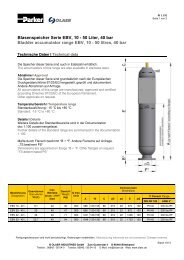
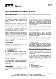
<strong>Assembly</strong>- , <strong>installation</strong>- <strong>and</strong> <strong>maintenance</strong> <strong>instruction</strong> manual for<br />
blad<strong>de</strong>r accumulators IBV / EBV 100 - 575, top reparable<br />
Content<br />
Seite<br />
0 Legend 2<br />
1 Overview 2<br />
2 Accumulator assembly <strong>and</strong> <strong>installation</strong> 3<br />
2.1 Check to be carried out on receipt of the accumulators 3<br />
2.2 Pressurizing, pre-charge pressure <strong>and</strong> checking 3<br />
2.2.1 Pre-charging the blad<strong>de</strong>r 3<br />
2.2.2 Checking the pre-charge pressure 3<br />
2.3 Installation 4<br />
2.3.1 Location 4<br />
2.3.2 Recommendations 4<br />
2.3.3 Putting into service 4<br />
2.4 Operation 4<br />
2.5 Instructions for <strong>maintenance</strong> <strong>and</strong> repair 4<br />
2.5.1 Overview 4<br />
2.5.2 Periodical check of pre-charge pressure 4<br />
2.5.3 Checking the pre-charge pressure 5<br />
2.5.4 Dismantling the accumulator 5<br />
2.5.5 Cleaning, inspection <strong>and</strong> repair 5<br />
2.5.6 Assemby 5/6<br />
2.5.7 Restarting into service 6<br />
3 Tester <strong>and</strong> pressurizer, type VGU 6<br />
3.1 Description 6<br />
3.2 H<strong>and</strong>ling 6<br />
3.2.1 Preparation 6<br />
3.2.2 Checking the pre-charge pressure 6<br />
3.2.3 Reducing the pre-charge pressure 6<br />
3.2.4 Raising / filling the pre-charge pressure 6<br />
3.2.5 Removal of the unit 6<br />
3.3 Spare parts 7/8<br />
Manufacturing tolerances are not consi<strong>de</strong>red. Changes reserved.<br />
© OLAER INDUSTRIES GmbH Zum Gunterstal 4 D-66440 Blieskastel<br />
Telefon.: 06842 / 92 04-0 Telefax: 06842 / 92 04-15 E-Mail: info@olaer.<strong>de</strong> Web: www.olaer.<strong>de</strong><br />
St<strong>and</strong> 11/13
doc 6.145<br />
Page 2 von 8<br />
0 Legend<br />
Danger<br />
This symbol refers to a high injury risk for people.<br />
It must be consi<strong>de</strong>red!<br />
Warning<br />
This symbol refers to an important information. Non-observance can lead to extensive<br />
damages.<br />
Safety informations must be respected!<br />
Note<br />
This symbol refers to an important information concerning the application.<br />
Non-observance can lead to disturbances!<br />
1 Overview<br />
* customer specification<br />
Manufacturing tolerances are not consi<strong>de</strong>red. Changes reserved.<br />
© OLAER INDUSTRIES GmbH Zum Gunterstal 4 D-66440 Blieskastel<br />
Telefon.: 06842 / 92 04-0 Telefax: 06842 / 92 04-15 E-Mail: info@olaer.<strong>de</strong> Web: www.olaer.<strong>de</strong><br />
St<strong>and</strong> 11/13
doc 6.145<br />
Page 3 von 8<br />
2 Accumulator assembly <strong>and</strong> <strong>installation</strong><br />
2.1 Check to be carried out on receipt of the acc.<br />
The hydropneumatic accumulators with blad<strong>de</strong>rs<br />
are carefully checked <strong>and</strong> tested in the factory<br />
before <strong>de</strong>livery. They are <strong>de</strong>livered assembled <strong>and</strong><br />
pre-charged with nitrogen in two possible choices:<br />
Pre-charged to a pressure P<br />
0<br />
as requested by<br />
the user with sealed valve<br />
pre-charged to 3 - 5 bar, in the case where no<br />
special request has been ma<strong>de</strong> by the user<br />
When the accumulators are received by the user, it<br />
is necessary to make sure:<br />
that they have suffered no damage during the<br />
course of transportation<br />
that the indications of the name plate with the<br />
or<strong>de</strong>r <strong>and</strong> <strong>de</strong>livery documents<br />
that the working pressure given on the name<br />
plate is at least equal to the maximum pressure<br />
used in the system<br />
that the protective cap of the air valve is installed<br />
that the plug of the "liquid si<strong>de</strong>" orifice has been<br />
removed before connexion<br />
2.2 Pressurizing, pre-charge press. a. checking<br />
Before use, the hydropneumatic accumulators with<br />
blad<strong>de</strong>rs must un<strong>de</strong>rgo two absolutely necessary<br />
operations:<br />
- Pressurizing of the blad<strong>de</strong>r with nitrogen<br />
- Checking the pre-charge pressure of the<br />
blad<strong>de</strong>r<br />
These operations must necessary be carried out by<br />
the user when the equipment has been <strong>de</strong>livered<br />
not charged or when they have been totally<br />
<strong>de</strong>presssurized in the case of <strong>maintenance</strong> or<br />
checks on constituent parts.<br />
2.2.1 Pre-charging the blad<strong>de</strong>r<br />
The blad<strong>de</strong>r can be pressurized before or after the<br />
<strong>installation</strong> of the accumulator in the system. Its<br />
purpose is to fill into the blad<strong>de</strong>r the quantity of nitrogen<br />
which <strong>de</strong>termines the working characteristics<br />
<strong>and</strong> lifetime of the equipment. The pre-charge pressure<br />
<strong>de</strong>pends on the working pressure, working<br />
temperature <strong>and</strong> application of the accumulator. It is<br />
carried out by means of the tester <strong>and</strong> pressurizer<br />
VGU (see chapter 3).<br />
Manufacturing tolerances are not consi<strong>de</strong>red. Changes reserved.<br />
It is necessary to use dry nitrogen from a<br />
bottle. The use of an air compressor or<br />
oxygen is strictly forbid<strong>de</strong>n!<br />
The pre-charge pressure is <strong>de</strong>termined by<br />
reference to:<br />
1. The characteristics of the system<br />
2. Expansion resulting from working temperatures<br />
3. Limits of working temperatures<br />
4. The function required, that is:<br />
Energy reserve:<br />
Equal to or lower than 9/10 of the minimum working<br />
pressure of the system <strong>and</strong> in no case lower than<br />
1/5 of the maximum pressure in that system.<br />
Anti pulsation:<br />
Equal to 60 % of the average working pressure<br />
Compensation for thermal expansion:<br />
80 % of the static pressure at minimal temperature<br />
Special cases:<br />
Consult the Parker <strong>Olaer</strong> technical service which<br />
will <strong>de</strong>termine the pre-charge pressure<br />
2.2.2 Checking the pre-charge pressure<br />
This check must not be carried out<br />
unless the accumulator is isolated <strong>and</strong><br />
dis-charged from the hydraulic fluid.<br />
Checking the pre-charge pressure is very important<br />
for the highest <strong>de</strong>gree of safety <strong>and</strong> for the proper<br />
operation of the Parker <strong>Olaer</strong> accumulators. It is<br />
carried out by means of the VGU (see chapter 3),<br />
specially <strong>de</strong>signed for that purpose.<br />
Before start-up it must be guaranteed that the<br />
pre-charge pressure is entirely correct for the<br />
tasks that the accumulator must carry out.<br />
1 week after start-up (either after <strong>installation</strong> or<br />
<strong>maintenance</strong>) check the pre-charge pressure. If<br />
there is no nitrogen loss next check has to be<br />
done 6 month later. After that the accumulator<br />
has to be checked annually.<br />
© OLAER INDUSTRIES GmbH Zum Gunterstal 4 D-66440 Blieskastel<br />
Telefon.: 06842 / 92 04-0 Telefax: 06842 / 92 04-15 E-Mail: info@olaer.<strong>de</strong> Web: www.olaer.<strong>de</strong><br />
St<strong>and</strong> 11/13
doc 6.145<br />
Page 4 von 8<br />
2 Accumulator assembly <strong>and</strong> <strong>installation</strong><br />
2.3 Installation<br />
2.3.1 Location<br />
For maximum efficiency the accumulator should be<br />
placed as close as possible to the components in<br />
the system to which it is related.<br />
Allow a free space of 200 mm over the air valve<br />
at the top to fit the tester <strong>and</strong> pressurizer VGU.<br />
Leave the gas valve accessible<br />
Leave the operating <strong>instruction</strong>s visible<br />
The accumulator has to be fixed with supporting<br />
brackets or legs.<br />
Normally accumulators can be used between<br />
temperatures of -15 °C to +80 °C. The permissible<br />
operating temperatures of the accumulator shown<br />
on the name plate are evi<strong>de</strong>nt.<br />
2.5 Instructions for <strong>maintenance</strong> <strong>and</strong> repair<br />
2.5.1 Overview<br />
In no case collars or supports may be<br />
wel<strong>de</strong>d to the body of the accumulator!<br />
The fluid port of the accumulator has to be flanged<br />
to the hydraulic system connection.<br />
2.3.2 Recommendations<br />
For efficient operation, it is advisable to take the<br />
following observations into account:<br />
Interpose a non-return valve between the pump<br />
<strong>and</strong> the accumulator (prevents back flow to the<br />
pump)<br />
Make sure that there is a pressure relief valve in<br />
the system to protect the accumulator<br />
If a pressure switch is used, take the pressure<br />
indication as close as possible to the<br />
accumulator.<br />
2.3.3 Putting into service<br />
Before putting the system un<strong>de</strong>r pressure, vent any<br />
air that the pipework may contain. Then put the<br />
system un<strong>de</strong>r maximum pressure to check whether<br />
the gaskets <strong>and</strong> connectors are leak proof.<br />
2.4 Operation<br />
The accumulator works <strong>maintenance</strong>-free <strong>and</strong><br />
needs no manual action except for periodical<br />
checks. When the machine will be stopped, we<br />
advise the isolation of the charged accumulator<br />
before <strong>de</strong>compressing the whole system, so as to<br />
ensure a rapid restart.<br />
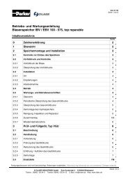
Fig. 2: Pressurizing unit<br />
Pos. Qty. Description<br />
1 1 Blad<strong>de</strong>r<br />
2 1 Gas plug<br />
3 1 Anti-extrusion ring<br />
4 1 Back-up ring<br />
5 1 O-ring<br />
6 1 O-ring<br />
7 1 Plate gas end<br />
8 1 Lock nut gas end<br />
9 1 Gas valve<br />
10 1 Valve guard<br />
11 1 Hexagon head screw<br />
12 1 Spring lock washer<br />
2.5.2 Periodical check of pre-charge pressure<br />
Make sure that the pre-charge pressure is<br />
maintained<br />
Carry out the check at least once during the first<br />
week of use, by means of the tester <strong>and</strong> pressurizer<br />
VGU (see chapter 3)<br />
Repeat this check every six months. Afterwards<br />
check it once a year in ordinary operating cond.<br />
Never forget to retighten the valve guard at the<br />
top<br />
Manufacturing tolerances are not consi<strong>de</strong>red. Changes reserved.<br />
© OLAER INDUSTRIES GmbH Zum Gunterstal 4 D-66440 Blieskastel<br />
Telefon.: 06842 / 92 04-0 Telefax: 06842 / 92 04-15 E-Mail: info@olaer.<strong>de</strong> Web: www.olaer.<strong>de</strong><br />
St<strong>and</strong> 11/13
doc 6.145<br />
Page 5 von 8<br />
2 Accumulator assembly <strong>and</strong> <strong>installation</strong><br />
2.5.3 Checking the pre-charge pressure<br />
(see fig. 3-2 page 7)<br />
Isolate the accumulator from the hydraulic sys.<br />
Discharge the accumulator on the fluid si<strong>de</strong><br />
Remove the valve guard <strong>and</strong> sealing cap of the<br />
gas valve<br />
Attach the tester <strong>and</strong> pressurizer VGU on the<br />
gas valve tighten by h<strong>and</strong> (see chapter 3)<br />
Make sure that the star knob of the bleed valve<br />
(20) is properly closed<br />
Turn star knob (6) clockwise until the pressure<br />
can be read on the pressure gauge<br />
Turn star knob of the bleed valve (20) anti clockwise<br />
<strong>and</strong> reduce the pressure<br />
To increase the pressure connect the charging<br />
hose (38) between the tester <strong>and</strong> pressurizer<br />
VGU <strong>and</strong> a nitrogen bottle. Open the stop valve<br />
of the nitrogen bottle slowly (a pressure-reducing<br />
valve on the nitrogen bottle is recomm<strong>and</strong>ed).<br />
Allow nitrogen to flow slowly into the accumulator<br />
until the <strong>de</strong>sired pre-charge pressure is<br />
reached<br />
Close the stop valve of the nitrogen bottle. Wait<br />
several minutes to stabilize the pressure <strong>and</strong><br />
temperature <strong>and</strong> then adjust the pressure<br />
accurately<br />
Turn star knob (6) anti clockwise to seal gas<br />
valve. Open the bleed valve (20) to exhaust gas<br />
from charging hose. Remove the tester <strong>and</strong><br />
pressurizer VGU<br />
Test the accumulator gas valve for leaks using a<br />
leak <strong>de</strong>tection spray or soapy water solution<br />
Replace the valve guard <strong>and</strong> sealing cap of the<br />
gas valve<br />
Increase slowly the hydraulic pressure on the<br />
fluid si<strong>de</strong> of the accumulator<br />
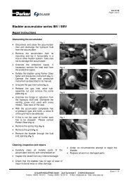
2.5.4 Dismantling the accumulator<br />
(see fig. 2 page 4)<br />
Discharge the accumulator on the fluid si<strong>de</strong>.<br />
Remove the valve guard (10).<br />
Remove the sealing cap of the gas valve (9).<br />
Vent the pre-charge pressure in the blad<strong>de</strong>r<br />
using the tester <strong>and</strong> pressurizer VGU (s.ch 3).<br />
Remove the gas valve (9)<br />
Remove the lock nut gas end (8)<br />
Remove the plate gas end (7) <strong>and</strong> its O-ring (6)<br />
Push the blad<strong>de</strong>r (1) with the gas plug (2) <strong>and</strong><br />
the anti-extrusion ring (3) into the shell<br />
Loose the anti-extrusion ring (3) from the gas<br />
plug (2), fold <strong>and</strong> remove it<br />
Remove the gas plug (2)<br />
Remove the blad<strong>de</strong>r (1)<br />
2.5.5 Cleaning, inspection <strong>and</strong> repair<br />
Clean all the metallic parts of the accumulator<br />
carefully <strong>and</strong> dry with compressed air<br />
Inspect the insi<strong>de</strong> of the shell on its cleanness<br />
<strong>and</strong> no internal damages<br />
Check that the O-rings show no signs of wear or<br />
rubbing<br />
Check that the blad<strong>de</strong>r shows no signs of major<br />
rubbing or other damages<br />
Replace all worn or damaged parts<br />
Don’t try to repair the blad<strong>de</strong>r un<strong>de</strong>r no<br />
circumstances<br />
2.5.6 <strong>Assembly</strong><br />
(see fig. 2 page 4)<br />
Ensure that no foreign parts remain in the shell<br />
of the accumulator<br />
Lubricate the blad<strong>de</strong>r <strong>and</strong> the insi<strong>de</strong> of the shell<br />
with the hydraulic system fluid, so as to facilitate<br />
the replacement of the blad<strong>de</strong>r<br />
Roll up the blad<strong>de</strong>r (1) longitudinally with fitted<br />
anti extrusion ring (3) <strong>and</strong> O-Ring (5) insert<br />
blad<strong>de</strong>r (1) trough hole into shell <strong>and</strong> fit the gas<br />
valve (9)<br />
Check that the blad<strong>de</strong>r (1) is neither fol<strong>de</strong>d nor<br />
twisted<br />
Pressurize the blad<strong>de</strong>r lightly with nitrogen <strong>and</strong><br />
put the gas valve (9) in the center of the shell<br />
opening<br />
Insert the gas plug (2) <strong>and</strong> install it on the<br />
blad<strong>de</strong>r (1)<br />
Fold the anti-extrusion ring (3), insert <strong>and</strong> install<br />
it on the gas plug (2)<br />
Install the plate gas end (7) with fitted O-Ring (6)<br />
Install the lock nut gas end (8) by h<strong>and</strong><br />
Tighten the gas valve (9) with a torque of 1,5 Nm<br />
Prefill the blad<strong>de</strong>r slowly with nitrogen to a<br />
pressure of 1 to 1.5 bar using the tester <strong>and</strong><br />
pressurizer VGU (see chapter 3)<br />
Tighten the lock nut gas end (8)<br />
Prefill the accumulator with the requested precharged<br />
pressure<br />
Tighten the sealing cap of the gas valve (9)<br />
Tighten the valve guard (10)<br />
Manufacturing tolerances are not consi<strong>de</strong>red. Changes reserved.<br />
© OLAER INDUSTRIES GmbH Zum Gunterstal 4 D-66440 Blieskastel<br />
Telefon.: 06842 / 92 04-0 Telefax: 06842 / 92 04-15 E-Mail: info@olaer.<strong>de</strong> Web: www.olaer.<strong>de</strong><br />
St<strong>and</strong> 11/13
doc 6.145<br />
Page 6 von 8<br />
2 Accumulator assembly <strong>and</strong> <strong>installation</strong><br />
2.5.7 Restarting into service<br />
Before putting the system un<strong>de</strong>r pressure, vent any<br />
air that the pipework may contain. Then put the<br />
system un<strong>de</strong>r maximum pressure to check whether<br />
the gaskets <strong>and</strong> connectors are leak proof.<br />
No welding, sol<strong>de</strong>ring or mechanical<br />
operations of any kind must be un<strong>de</strong>rtaken<br />
on the accumulator!<br />
3 Tester <strong>and</strong> pressurizer, type VGU<br />
3.1 Description<br />
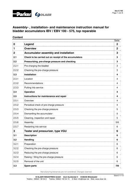
The VGU tester <strong>and</strong> pressurizer is used for the<br />
charging of blad<strong>de</strong>r, piston <strong>and</strong> membrane accumulators<br />
with nitrogen <strong>and</strong> to test or change the<br />
pre-charge pressure. It is screwed onto the gas<br />
valve of the hydropneumatic accumulator <strong>and</strong><br />
connected with a hose to a st<strong>and</strong>ard nitrogen bottle.<br />
If only the pre-charge pressure needs to be<br />
checked, the connection of the charging hose is not<br />
necessary.<br />
Each unit comprises of:<br />
Tester <strong>and</strong> pressurizer with manometer, return<br />
valve on the charging connection release valve,<br />
valve spindle to open the gas inlet valve on the<br />
accumulator<br />
Charging hose, length 2,5 m<br />
Connections for the accumulator 7 / 8 “ - 14 UNF;<br />
5 / 8 “ - 18 UNF; 0,305“ - 32 NFT; M 28 x 1,5<br />
Plastic protective case<br />
3.2 H<strong>and</strong>ling (see fig. 3-2 page 7)<br />
3.2.1 Preparation<br />
Discharge the fluid si<strong>de</strong> of the accumulator<br />
before each test <strong>and</strong> before filling or refilling with<br />
nitrogen<br />
Remove the valve guard <strong>and</strong> sealing cap of the<br />
gas valve<br />
Attach the pressurizer with<br />
adapter (25, 30 or 36) onto<br />
the gas valve<br />
Check that the bleed valve<br />
is closed. Turn the star knob<br />
(20) clockwise<br />
3.2.2 Checking the pre-charge pressure<br />
Turn the star knob (6) clockwise. This opens the<br />
gas valve <strong>and</strong> the pressure can be read on the<br />
manometer.<br />
3.2.3 Reducing the pre-charge pressure<br />
Turn the star knob (20) of the bleed valve slowly<br />
anti clockwise. The nitrogen escapes to the open.<br />
3.2.4 Raising / filling the pre-charge pressure<br />
Never prefill with oxygen: Risk of<br />
explosion! If the pressure of the nitrogen<br />
bottle is higher than the permitted<br />
accumulator working pressure, a<br />
pressure-reducing valve must be<br />
connected ahead.<br />
Connect one end of the charging hose to the<br />
return valve (7) <strong>and</strong> the other to a commercial<br />
nitrogen bottle<br />
Open the stop valve on the nitrogen bottle<br />
carefully. Allow the nitrogen to flow slowly into<br />
the accumulator, until the <strong>de</strong>sired pre-charge<br />
pressure is reached<br />
Close the stop valve of the nitrogen bottle. After<br />
5 to 10 minutes (temperature stabilisation) check<br />
the pre-charge pressure again <strong>and</strong> correct, if<br />
necessary (see 3.2.2 - 3.2.4)<br />
3.2.5 Removal of the unit<br />
Turn the star knob (6) back<br />
Turn the star knob (20) anti clockwise to exhaust<br />
gas from the pressurizer<br />
Remove the pressurizer<br />
Fig. 3-1<br />
Tester <strong>and</strong> pressurizer, type VGU<br />
Manufacturing tolerances are not consi<strong>de</strong>red. Changes reserved.<br />
© OLAER INDUSTRIES GmbH Zum Gunterstal 4 D-66440 Blieskastel<br />
Telefon.: 06842 / 92 04-0 Telefax: 06842 / 92 04-15 E-Mail: info@olaer.<strong>de</strong> Web: www.olaer.<strong>de</strong><br />
St<strong>and</strong> 11/13
doc 6.145<br />
Page 7 von 8<br />
3 Tester <strong>and</strong> pressurizer, type VGU<br />
3.3 Spare parts<br />
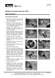
Pos. Qty. Description<br />
1 1 Valve body<br />
2 1 Valve spindle<br />
3 1 Bolts<br />
4 1 Split ring<br />
5 1 Spigot nut<br />
6 1 Star knob<br />
7 1 Return valve<br />
8 1 O-ring<br />
9 1 Flat seal<br />
10 1 Hexagon nut<br />
11 1 Retaining ring<br />
12 1 Compression spring<br />
13 1 O-ring<br />
14 1 O-ring<br />
15 1 Retaining ring<br />
16 1 Centre-grooved dowel pin<br />
17 1 Name plate<br />
18 1 Connect. for manom. G 1 / 4 "<br />
19 1 Copper seal<br />
20 1 Star knob<br />
21 1 Sealing gl<strong>and</strong><br />
22 1 Valve spindle<br />
23 1 Valve ball<br />
24 1 Knurled cap<br />
25 1 Adapter SAE 7 / 8 " - 14UNF compl.<br />
26 1 Retainig ring<br />
27 1 Adapter SAE 7 / 8 " - 14 UNF<br />
28 1 Valve spindle<br />
29 1 O-ring<br />
30 1 Adapter SAE 5 / 8 " - 18 UNF compl.<br />
31 1 Retaining ring<br />
32 1 Adapter SAE 5 / 8 " - 18 UNF<br />
33 1 Valve spindle<br />
34 1 O-ring<br />
35 1 Flat seal<br />
36 1 Connect 0,305"-32 NFT<br />
37 1 Gasket assembly (complete set)<br />
Fig. 3-2: Tester <strong>and</strong> pressurizer , type VGU<br />
Manufacturing tolerances are not consi<strong>de</strong>red. Changes reserved.<br />
© OLAER INDUSTRIES GmbH Zum Gunterstal 4 D-66440 Blieskastel<br />
Telefon.: 06842 / 92 04-0 Telefax: 06842 / 92 04-15 E-Mail: info@olaer.<strong>de</strong> Web: www.olaer.<strong>de</strong><br />
St<strong>and</strong> 11/13
doc 6.145<br />
Page 8 von 8<br />
3 Tester <strong>and</strong> pressurizer, type VGU<br />
Fig. 3-3: Tester <strong>and</strong> pressurizer , type VGU<br />
38 Charging hose<br />
40 Connections for foreign nitrogen flasks<br />
40b GB / AUS R 5 / 8 “ external<br />
40c USA 24,51 x 1 / 14 ” external<br />
40d Italy 21,7 x 1 / 14 “ external<br />
40e Japan 22 x 1 / 14 “ internal<br />
40f Japan W 23 x 1 / 14 “ external<br />
40g Brazil R 1 / 2 “ internal<br />
40h F, B, E 21,7 x 1 / 4 ” internal<br />
40i China M 22 x 1.5 internal<br />
40k China<br />
5 / 8 “ internal<br />
40l Malaysia G 7 / 8 “ external<br />
40m Trinidad<br />
7 / 8 “ - 14 UNF external<br />
40n Bulgaria<br />
3 / 4 “ internal<br />
40o Philippines W 23 x 1 / 14 “ left<br />
Manufacturing tolerances are not consi<strong>de</strong>red. Changes reserved.<br />
© OLAER INDUSTRIES GmbH Zum Gunterstal 4 D-66440 Blieskastel<br />
Telefon.: 06842 / 92 04-0 Telefax: 06842 / 92 04-15 E-Mail: info@olaer.<strong>de</strong> Web: www.olaer.<strong>de</strong><br />
St<strong>and</strong> 11/13