DLP-2232M-G - FTDI
DLP-2232M-G - FTDI
DLP-2232M-G - FTDI

Create successful ePaper yourself
Turn your PDF publications into a flip-book with our unique Google optimized e-Paper software.
<strong>DLP</strong>-<strong>2232M</strong>-G MODULE / EVALUATION KIT<br />
*LEAD-FREE*<br />
1.0 Introduction<br />
The <strong>DLP</strong>-<strong>2232M</strong>-G utilizes <strong>FTDI</strong>'s third-generation USB UART/FIFO I.C., the<br />
FT2232D. This low-cost development tool features two Multi-Purpose UART/FIFO<br />
controllers that can be configured individually in several different modes. In addition to<br />
the UART interface, FIFO interface, and Bit-Bang IO modes of the second-generation<br />
FT232BM and FT245BM devices, the FT2232D offers a variety of additional modes of<br />
operation including a Multi-Protocol Synchronous Serial Engine interface designed<br />
specifically for synchronous serial protocols such as JTAG and SPI bus.<br />
The <strong>DLP</strong>-<strong>2232M</strong>-G features a quality four-layer printed circuit board with a solid ground<br />
plane, an integral 93C56 EEPROM on board for easy OEM customization and a standard<br />
40-pin, 0.6in wide footprint. Integral power control and on-board MOSFET power<br />
switch make the <strong>DLP</strong>-<strong>2232M</strong>-G a perfect choice for USB bus-powered, high-power<br />
designs as well as self- and low-powered products.<br />
Rev 1.6 (May 2009)<br />
1<br />
<strong>DLP</strong>-<strong>2232M</strong>-G <strong>DLP</strong> Design, Inc.
1.1 Features Summary<br />
• Single board, USB Dual Channel Serial / Parallel Ports with a variety of configurations<br />
• Entire USB protocol handled on-board. No USB-specific firmware programming<br />
required<br />
• <strong>DLP</strong>-USB232M-style UART interface option with full Handshaking & Modem<br />
interface signals<br />
• UART Interface supports 7/8 bit data, 1/2 stop bits, and Odd/Even/Mark/Space/No<br />
Parity<br />
• Transfer Data Rate 300 to 1 Mega Baud (RS232)<br />
• Transfer Data Rate 300 to 3 Mega Baud (TTL and RS422 / RS485)<br />
• Auto Transmit Enable control for RS485 serial applications using TXDEN pin<br />
• <strong>DLP</strong>-USB245M-style FIFO interface option with bi-directional data bus and simple 4-<br />
wire handshake interface<br />
• Transfer Data Rate up to 1 MegaByte / Second<br />
• Enhanced Bit-Bang Mode interface option<br />
• New Synchronous Bit-Bang Mode interface option<br />
• New CPU-Style FIFO Interface Mode option<br />
• New Multi-Protocol Synchronous Serial Engine (MPSSE) interface option<br />
• New MCU Host Bus Emulation Mode option<br />
• New Fast Opto-Isolated Serial Interface Mode option<br />
• Interface mode and USB Description strings configurable in on-board EEPROM<br />
• EEPROM Configurable in-circuit via USB<br />
• Support for USB Suspend and Resume conditions via PWREN#, and SI/WUx pins<br />
• Support for bus powered, self powered, and high-power bus powered USB<br />
configurations<br />
• Integrated Power-On-Reset circuit, with optional Reset input and Reset Output pins<br />
• 5V and 3.3V logic IO Interfacing with independent level conversion on each channel<br />
• USB Bulk or Isochronous data transfer modes<br />
• 4.35V to 5.25V single supply operating voltage range<br />
• UHCI / OHCI / EHCI host controller compatible<br />
• USB 2.0 Full Speed (12 Mbits / Second) compatible<br />
• Standard 40-pin, 0.6in wide footprint<br />
VIRTUAL COM PORT (VCP) DRIVERS APPLICATION AREAS<br />
• Windows 98 / 98 SE / 2000 / ME / XP • USB Dual Port RS232 Converters<br />
• Windows CE **<br />
• USB Dual Port RS422 / RS485<br />
• MAC OS-8 and OS-9**<br />
• Upgrading Legacy Peripheral Designs<br />
• MAC OS-X**<br />
• USB Instrumentation<br />
• Linux 2.40 and greater**<br />
• USB JTAG Programming<br />
[ ** = In planning or under development ] • USB to SPI Bus Interfaces<br />
• USB Industrial Control<br />
D2XX (Direct Drivers + DLL S/W<br />
• Field Upgradeable USB Products<br />
• Windows 98 / 98 SE / 2000 / ME / XP • Galvanically Isolated Products<br />
With USB Interface<br />
Rev 1.6 (May 2009)<br />
2<br />
<strong>DLP</strong>-<strong>2232M</strong>-G <strong>DLP</strong> Design, Inc.
1.2 General Description<br />
The <strong>DLP</strong>-<strong>2232M</strong>-G module is a USB interface that incorporates the functionality of two<br />
<strong>DLP</strong>-USB2xxM modules into a single 40-pin module. A single downstream USB port is<br />
converted to two IO channels that can each be individually configured as a <strong>DLP</strong>-<br />
USB232M-style UART interface, or a <strong>DLP</strong>-USB245M-style FIFO interface, without the<br />
need to add a USB hub.<br />
There are also several new modes which can be enabled in the external EEPROM, or by<br />
using DLL driver commands. These include Synchronous Bit-Bang Mode, a CPU-Style<br />
FIFO Interface Mode, a Multi-Protocol Synchronous Serial Engine Interface Mode, MCU<br />
Host Bus Emulation Mode, and Fast Opto-Isolated Serial Interface Mode. Additionally,<br />
a new high output drive level option means that the device UART / FIFO IO pins will<br />
drive out at around three times the normal power level, allowing the data bus to be shared<br />
by several devices.<br />
Classic BM-style Asynchronous Bit-Bang Mode is also supported, but has been enhanced<br />
to give the user access to the device’s internal RD# and WR# strobes.<br />
<strong>FTDI</strong> provides a royalty free Virtual Com Port (VCP) driver that makes the peripheral<br />
ports look like a standard COM port to the PC. Most existing software applications<br />
should be able interface with the Virtual Com Port simply by reconfiguring them to use<br />
the new ports created by the driver. Using the VCP drivers, an application programmer<br />
would communicate with the device in exactly the same way as they would a regular PC<br />
COM port - using the Windows VCOMM API calls or a COM port library.<br />
The FT2232D driver also incorporates the functions defined for <strong>FTDI</strong>’s D2XX drivers,<br />
allowing applications programmers to interface software directly to the device using a<br />
Windows DLL.<br />
Rev 1.6 (May 2009)<br />
3<br />
<strong>DLP</strong>-<strong>2232M</strong>-G <strong>DLP</strong> Design, Inc.
2.0 Features and Enhancements<br />
The <strong>DLP</strong>-<strong>2232M</strong>-G incorporates all of the enhancements introduced for the second<br />
generation <strong>DLP</strong>-USB232M and <strong>DLP</strong>-USB245M modules, summarized here:<br />
• Two Individually Configurable IO Channels<br />
Each of the <strong>DLP</strong>-<strong>2232M</strong>-G’s Channels (A and B) can be individually configured as a<br />
<strong>DLP</strong>-USB232M-style UART interface, or as a DL-USB245M-style FIFO interface.<br />
Additionally, these channels can be configured in a number of special IO modes.<br />
• Integrated Power-On-Reset (POR) circuit<br />
The module incorporates an internal POR function. A RESET# pin is available to allow<br />
external logic to reset the module where required, however for most applications this pin<br />
can simply be left disconnected as the RESET input to the FT2232D is pulled to VCC<br />
through a 47K resistor. A RSTOUT# pin is provided in order to allow the new POR<br />
circuit to provide a stable reset to external MCU and other devices.<br />
• Integrated level converter on UART / FIFO interface and control signals<br />
Each channel of the <strong>DLP</strong>-<strong>2232M</strong>-G has its own independent VCCIO pin that can be<br />
supplied by between 3V to 5V. This allows each channel’s output voltage drive level to<br />
be individually configured. Thus allowing, for example, 3.3V logic to be interfaced to<br />
the device without the need for external level converter I.C.’s.<br />
• Improved power management control for high-power USB Bus Powered devices<br />
The PWREN# pin of the FT2232D directly drives a P-Channel MOSFET for applications<br />
where power switching of external circuitry is required. The BM pull down enable<br />
feature (configured in the external EEPROM) is also retained. This will make the<br />
module gently pull down on the FIFO / UART IO lines when the power is shut off<br />
(PWREN# is high). In this mode, any residual voltage on external circuitry is bled to<br />
GND when power is removed, thus ensuring that external circuitry controlled by<br />
PWREN# resets reliably when power is restored.<br />
• Support for Isochronous USB Transfers<br />
Whilst USB Bulk transfer is usually the best choice for data transfer, the scheduling time<br />
of the data is not guaranteed. For applications where scheduling latency takes priority<br />
over data integrity such as transferring audio and low bandwidth video data, the <strong>DLP</strong>-<br />
<strong>2232M</strong>-G offers the option of USB Isochronous transfer via configuration of bit in the<br />
EEPROM.<br />
• Send Immediate / Wake Up Signal Pin on each channel<br />
There is a Send Immediate / Wake Up (SI/WU) signal pin on each of the two channels.<br />
These combine two functions on one pin. If USB is in suspend mode (and remote<br />
wakeup is enabled in the EEPROM), strobing this pin low will cause the device to<br />
request a resume from suspend (WakeUp) on the USB Bus. Normally, this can be used<br />
to wake up the Host PC. During normal operation, if this pin is strobed low any data in<br />
the device RX buffer will be sent out over USB on the next Bulk-IN request from the<br />
Rev 1.6 (May 2009)<br />
4<br />
<strong>DLP</strong>-<strong>2232M</strong>-G <strong>DLP</strong> Design, Inc.
drivers regardless of the packet size. This can be used to optimize USB transfer speed for<br />
applications that send small packets of data to the host PC.<br />
• Programmable Receive Buffer Timeout<br />
The TX buffer timeout is programmable over USB in 1ms increments from 1ms to<br />
255ms, thus allowing the module to be better optimized for protocols requiring faster<br />
response times from short data packets.<br />
• Baud Rate Pre-Scaler Divisors<br />
The <strong>DLP</strong>-<strong>2232M</strong>-G (UART mode) baud rate pre-scaler supports division by (n+0),<br />
(n+0.125), (n+0.25), (n+0.375), (n+0.5), (n+0.625), (n+0.75) and (n+0.875) where n is an<br />
integer between 2 and 16,384.<br />
• USB 2.0 (full speed option)<br />
An EEPROM based option allows the <strong>DLP</strong>-<strong>2232M</strong>-G to return a USB 2.0 device<br />
descriptor as opposed to USB 1.1. Note: The device would be a USB 2.0 Full Speed<br />
device (12Mb/s) as opposed to a USB 2.0 High Speed device (480Mb/s).<br />
For more details on these features please see the FT232BM and FT245BM datasheets and<br />
application notes.<br />
In addition to the <strong>DLP</strong>-USB2xxM module features, the <strong>DLP</strong>-<strong>2232M</strong>-G incorporates the<br />
following new features and interface modes:<br />
• Enhanced Asynchronous Bit-Bang Interface<br />
The <strong>DLP</strong>-<strong>2232M</strong>-G supports <strong>FTDI</strong>’s BM chip Bit Bang mode. In Bit Bang mode, the<br />
eight FIFO data lines can be switched between FIFO interface mode and an 8-bit Parallel<br />
IO port. Data packets can be sent to the device and they will be sequentially sent to the<br />
interface at a rate controlled by an internal timer (equivalent to the baud rate prescaler).<br />
With the <strong>DLP</strong>-<strong>2232M</strong>-G module, this mode has been enhanced so that the internal RD#<br />
and WR# strobes are now brought out of the device which can be used to allow external<br />
logic to be clocked by accesses to the Bit-Bang IO bus.<br />
• Synchronous Bit-Bang Interface<br />
With Synchronous Bit-Bang Mode, the device is only read when it is written to, as<br />
opposed to asynchronously by the data rate generator. This makes it easier for the<br />
controlling program to measure the response to an output stimulus, as the data returned is<br />
synchronous to the output data.<br />
• High Output Drive Level Capability<br />
The IO interface pins can be made to drive out at 12 mA, instead of the normal 4 mA<br />
allowing multiple devices to be interfaced to the bus.<br />
Rev 1.6 (May 2009)<br />
5<br />
<strong>DLP</strong>-<strong>2232M</strong>-G <strong>DLP</strong> Design, Inc.
• CPU-Style FIFO Interface<br />
The CPU style FIFO interface is essentially the same function as the classic FT245<br />
interface, however the bus signals have been redefined to make them easier to interface to<br />
a CPU bus.<br />
• Multi-Protocol Synchronous Serial Engine Interface (M.P.S.S.E.)<br />
The Multi-Protocol Synchronous Serial Engine (MPSSE) interface is a new option<br />
designed to interface efficiently with synchronous serial protocols such as JTAG and SPI<br />
Bus. It is very flexible in that it can be configured for different industry standards, or<br />
proprietary bus protocols. For instance, it is possible to connect one of the <strong>DLP</strong>-<strong>2232M</strong>-<br />
G’s channels to an SRAM configurable FPGA as supplied by vendors such as Altera and<br />
Xilinx. The FPGA device would normally be un-configured (i.e. have no defined<br />
function) at power-up. Application software on the PC could use the MPSSE to<br />
download configuration data to the FPGA over USB. This data would define the<br />
hardware’s function and then, after the FPGA device is configured, the <strong>DLP</strong>-<strong>2232M</strong>-G<br />
can switch back into FIFO interface mode to allow the programmed FPGA device to<br />
communicate with the PC over USB. The other <strong>DLP</strong>-<strong>2232M</strong>-G channel would also be<br />
available for other devices.<br />
This approach would allow a customer to create a “generic” USB peripheral; who’s<br />
hardware function can be defined under control of the application software. The FPGA<br />
based hardware could be easily upgraded or totally changed simply by changing the<br />
FPGA configuration data file. (See the <strong>FTDI</strong> MORPH-IC or <strong>DLP</strong>-Design <strong>DLP</strong>-2232PB<br />
and <strong>DLP</strong>-2232SY development modules for practical examples)<br />
• MCU Host Bus Emulation<br />
This new mode combines the ‘A’ and ‘B’ bus interface to make the <strong>DLP</strong>-<strong>2232M</strong>-G<br />
interface emulate a standard 8048 / 8051 style MCU bus. This allows peripheral devices<br />
for these MCU families to be directly attached to the <strong>DLP</strong>-<strong>2232M</strong>-G with IO being<br />
performed over USB with the help of MPSSE interface technology.<br />
• Fast Opto-Isolated Serial Interface<br />
A new proprietary <strong>FTDI</strong> protocol is designed to allow galvanically isolated devices to<br />
communicate synchronously with the <strong>DLP</strong>-<strong>2232M</strong>-G using just 4 wires (two dual optoisolators).<br />
The peripheral circuitry controls the data transfer rate in both directions,<br />
whilst maintaining full data integrity. Maximum USB full speed data rates can be<br />
achieved. Both ‘A’ and ‘B’ channels can communicate over the same 4-wire interface if<br />
desired.<br />
Rev 1.6 (May 2009)<br />
6<br />
<strong>DLP</strong>-<strong>2232M</strong>-G <strong>DLP</strong> Design, Inc.
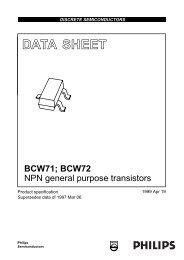
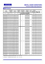
3.0 <strong>DLP</strong>-<strong>2232M</strong>-G Module Simplified Block Diagram<br />
MOSFET<br />
Power<br />
Switch<br />
USB Type 'B'<br />
connector to<br />
Host PC/Mac<br />
DP, DM<br />
PWREN#<br />
3.3 Volt LDO<br />
FT2232C<br />
Channel A<br />
Multi-purpose UART /<br />
FIFO Controller<br />
Channel B<br />
Multi-purpose UART /<br />
FIFO Controller<br />
40 Pin,<br />
.6 inch<br />
Header<br />
6MHz Resonator<br />
93C56<br />
EEPROM<br />
3.1 Functional Block Descriptions<br />
• 6MHz Oscillator<br />
The 6MHz Oscillator cell generates a 6MHz reference clock input to the x8 Clock<br />
multiplier from an external 6MHz ceramic resonator.<br />
• Multi-Purpose UART / FIFO Controllers<br />
The Multi-purpose UART / FIFO controllers handle the transfer of data between the Dual<br />
Port RX and TX buffers and the UART / FIFO transmit and receive registers. When<br />
configured as a UART it performs asynchronous 7/8 bit parallel to serial and serial to<br />
parallel conversion of the data on the RS232 (RS422 and RS485) interface. Control<br />
signals supported by UART mode include RTS, CTS, DSR, DTR, DCD and RI. There<br />
are also transmitter enable control signal pins (TXDEN) provided to assist with<br />
interfacing to RS485 transceivers. RTS/CTS, DSR/DTR and X-On/X-Off handshaking<br />
options are also supported. Handshaking, where required, is handled in hardware to<br />
Rev 1.6 (May 2009)<br />
7<br />
<strong>DLP</strong>-<strong>2232M</strong>-G <strong>DLP</strong> Design, Inc.
ensure fast response times. The UARTs also support the RS232 BREAK setting and<br />
detection conditions.<br />
• EEPROM Interface<br />
The on-board 93C56 EEPROM allows each of the <strong>DLP</strong>-<strong>2232M</strong>-G module’s channels to<br />
be independently configured as a serial UART (232 mode), or a parallel FIFO (245<br />
mode). The EEPROM is used to enable the CPU-style FIFO interface, and Fast Opto-<br />
Isolated Serial interface modes. The driver type selection (VCP or D2XX) is also stored<br />
in the EEPROM.<br />
The EEPROM can also be used to customize the USB VID, PID, Serial Number, Product<br />
Description Strings and Power Descriptor value of the <strong>DLP</strong>-<strong>2232M</strong>-G for OEM<br />
applications. Other parameters controlled by the EEPROM include Remote Wake Up,<br />
Isochronous Transfer Mode, Soft Pull Down on Power-Off and USB 2.0 descriptor<br />
modes.<br />
The EEPROM is programmable in-circuit via USB using the MPROG utility program<br />
available from both www.dlpdesign.com and <strong>FTDI</strong>’s web site (www.ftdichip.com).<br />
Rev 1.6 (May 2009)<br />
8<br />
<strong>DLP</strong>-<strong>2232M</strong>-G <strong>DLP</strong> Design, Inc.
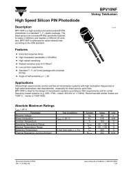
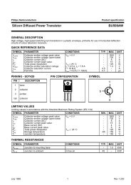
4.0 Module Pin-Out<br />
1<br />
40 Pin,<br />
.6 inch<br />
Header<br />
40<br />
FT2232C<br />
6.000<br />
20<br />
USB 'B'<br />
Type 21<br />
Connector<br />
4.1 Pin Definitions<br />
Figure 2. Pin-Out (40 Pin DIP Header )<br />
This section describes the operation of the <strong>DLP</strong>-<strong>2232M</strong>-G pins. Common pins are<br />
defined in the first section and the I/O pins are defined by chip mode. More detailed<br />
descriptions of the operation of the I/O pins are provided in section x. (was 9)<br />
4.2 Common Pins<br />
The operation of the following <strong>DLP</strong>-<strong>2232M</strong>-G pins stay the same, regardless of the<br />
operating mode.<br />
Pin# Signal Type Description<br />
27 RSTIN# Input Can be used by an external device to reset the FT2232D. If<br />
not required, can be left disconnected.<br />
26 RSTOUT# Output Output of the internal Reset Generator. Stays high<br />
impedance for ~5ms after VCC > 3.5V and the<br />
internal clock starts up, then clamps it’s output to the 3.3V<br />
output of the internal regulator.<br />
Taking RESET# low will also force RSTOUT# to drive<br />
low. RSTOUT# is NOT affected by a USB Bus Reset.<br />
19 EXTVCC PWR +4.35 to +5.25 volt VCC to the device core, LDO and non-<br />
Rev 1.6 (May 2009)<br />
9<br />
<strong>DLP</strong>-<strong>2232M</strong>-G <strong>DLP</strong> Design, Inc.
UART / FIFO controller interface pins.<br />
Device Analog Power Supply for the internal x8 clock<br />
multiplier.<br />
18 VCCIOA PWR +3.0 to +5.25 volt VCC to the UART/FIFO Channel A<br />
interface pins. When interfacing with 3.3V external logic<br />
connect VCCIO to the 3.3V supply of the external logic,<br />
otherwise connect to VCC to drive out at 5V CMOS level.<br />
17 VCCIOB PWR +3.0 volt to +5.25 volt VCC to the UART/FIFO Channel B<br />
interface pins. When interfacing with 3.3V external logic<br />
connect VCCIO to the 3.3V supply of the external logic,<br />
otherwise connect to VCC to drive out at 5V CMOS level.<br />
20 PORTVCC PWR Power from USB port. Connect to EXTVCC if module is to<br />
be powered by the USB port (typical configuration).<br />
500mA maximum current available to USB adapter and<br />
target electronics if USB device is configured for high<br />
power.<br />
16 VCCSW PWR Output of the MOSFET power switch, activated after<br />
enumeration.<br />
21 VCCUSB PWR Filtered +3.0 volt to +5.25 volt EXTVCC from either the<br />
host USB port or user supplied external power supply.<br />
4.3 IO Pin Definitions by Chip Mode<br />
The definition of the following pins vary according to the module’s mode:<br />
Pin#<br />
Generic<br />
Pin<br />
Name<br />
232 UART<br />
Mode<br />
245<br />
FIFO<br />
Mode<br />
Pin Definitions by Chip Mode *Note 2<br />
Enhanced<br />
CPU Asynchronous MPSSE<br />
FIFO and<br />
*Note 4<br />
Interface Synchronous<br />
Mode Bit-Bang<br />
Modes<br />
MCU Host<br />
Bus<br />
Enumeration<br />
Mode<br />
*Note 5<br />
Fast<br />
Opto-<br />
Isolated<br />
Serial<br />
Mode<br />
40 ADBUS0 TXD D0 D0 D0 TCK/SK AD0 *Note 3<br />
39 ADBUS1 RXD D1 D1 D1 TDI/DU AD1<br />
38 ADBUS2 RTS# D2 D2 D2 TDO/D1 AD2<br />
37 ADBUS3 CTS# D3 D3 D3 TMS/CS AD3<br />
36 ADBUS4 DTR# D4 D4 D4 GPIOL0 AD4<br />
35 ADBUS5 DSR# D5 D5 D5 GPIOL1 AD5<br />
34 ADBUS6 DCD# D6 D6 D6 GPIOL2 AD6<br />
33 ADBUS7 RI# D7 D7 D7 GPIOL3 AD7<br />
32 ACBUS0 TXDEN RXF# CS# WR# *Note 6 GPIOH0 I/O0<br />
31 ACBUS1 SLEEP# TXE# A0 RD# *Note 6 GPIOH1 I/O1<br />
30 ACBUS2 RXLED# RD# RD# WR# *Note 7 GPIOH2 IORDY#<br />
29 ACBUS3 TXLED# WR WR# RD# *Note 7 GPIOH3 OSC<br />
28 SI/WUA SI/WUA SI/WUA SI/WUA<br />
Rev 1.6 (May 2009)<br />
10<br />
<strong>DLP</strong>-<strong>2232M</strong>-G <strong>DLP</strong> Design, Inc.
Pin#<br />
Generic<br />
Pin<br />
Name<br />
232 UART<br />
Mode<br />
245<br />
FIFO<br />
Mode<br />
Pin Definitions by Chip Mode *Note 2<br />
Enhanced<br />
CPU Asynchronous MPSSE<br />
FIFO and<br />
*Note 4<br />
Interface Synchronous<br />
Mode Bit-Bang<br />
Modes<br />
MCU Host<br />
Bus<br />
Enumeration<br />
Mode<br />
*Note 5<br />
Fast<br />
Opto-<br />
Isolated<br />
Serial<br />
Mode<br />
13 BDBUS0 TXD D0 D0 D0 AD8 FSDI<br />
12 BDBUS1 RXD D1 D1 D1 AD9 FSCLK<br />
11 BDBUS2 RTS# D2 D2 D2 AD10 FSDO<br />
10 BDBUS3 CTS# D3 D3 D3 AD11 FSCTS<br />
9 BDBUS4 DTR# D4 D4 D4 AD12 *Note 3<br />
8 BDBUS5 DSR# D5 D5 D5 AD13<br />
7 BDBUS6 DCD# D6 D6 D6 AD14<br />
6 BDBUS7 RI# D7 D7 D7 AD15<br />
5 BCBUS0 TXDEN RXF# CS# WR# *Note 8 CS#<br />
4 BCBUS1 SLEEP# TXE# A0 RD# *Note 8 ALE<br />
3 BCBUS2 RXLED# RD# RD# WR# *Note 7 RD#<br />
2 BCBUS3 TXLED# WR WR# RD# *Note 7 WR#<br />
1 SI/WUB SI/WUB SI/WUB<br />
*Note 2 : 232 UART, 245 FIFO, CPU FIFO Interface, and Fast Opto-Isolated modes are<br />
enabled in the external EEPROM. Enhanced Asynchronous and Synchronous Bit-Bang<br />
modes, MPSSE, and MCU Host Bus Emulation modes are enabled using driver<br />
commands.<br />
*Note 3 : Channel A can be configured in another IO mode if channel B is in Fast Opto-<br />
Isolated Serial Mode. If both Channel A and Channel B are in Fast Opto-Isolated Serial<br />
Mode all of the IO will be on Channel B.<br />
*Note 4 : MPSSE is Channel A only.<br />
*Note 5 : MCU Host Bus Emulation requires both Channels.<br />
*Note 6 : The Bit-Bang Mode (synchronous and asynchronous) WR# and RD# strobes<br />
are on these pins when the main Channel mode is 245 FIFO, CPU FIFO interface, or Fast<br />
Opto-Isolated Serial Modes.<br />
*Note 7 : The Bit-Bang Mode (synchronous and asynchronous) WR# and RD# strobes<br />
are on these pins when the main Channel mode is 232 UART Mode.<br />
*Note 8 : The Bit-Bang Mode (synchronous and asynchronous) WR# and RD# strobes<br />
are on these pins when the main Channel mode is 245 FIFO, CPU FIFO interface. Bit-<br />
Bang mode is not available on Channel B when Fast Opto-Isolated Serial Mode is<br />
enabled.<br />
Rev 1.6 (May 2009)<br />
11<br />
<strong>DLP</strong>-<strong>2232M</strong>-G <strong>DLP</strong> Design, Inc.
5.0 Mechanical Dimensions<br />
Inches (mm)<br />
0.05 typ.<br />
( 1.3typ.)<br />
2.2 typ.<br />
(55.9 typ.)<br />
0.25 typ.<br />
(6.4 typ.)<br />
0.1 typ.<br />
(2.54 typ.)<br />
0.65 typ.<br />
(16.5 typ.)<br />
0.48 typ.<br />
(12.2 typ.)<br />
0.25 typ.<br />
(6.4typ.)<br />
0.7 typ.<br />
(17.8 typ.)<br />
0.50 typ.<br />
(12.7 typ.)<br />
**Components on top and<br />
bottom of PCB<br />
**<br />
0.6 typ.<br />
(15.2 typ.)<br />
0.7 typ.<br />
(17.8 typ.)<br />
0.36 typ.<br />
(9.1 typ.)<br />
Rev 1.6 (May 2009)<br />
12<br />
<strong>DLP</strong>-<strong>2232M</strong>-G <strong>DLP</strong> Design, Inc.
6.0 Absolute Maximum Ratings<br />
These are the absolute maximum ratings for the FT2232D device. Exceeding these may<br />
cause permanent damage to the device.<br />
• Storage Temperature …………………………………………..-65oC to + 150oC<br />
• Ambient Temperature (Power Applied)……………………….. 0°C to 70°C<br />
• VCC Supply Voltage …………………………………………..-0.5V to +6.00V<br />
• DC Input Voltage - Inputs ……………………………………..-0.5V to VCC + 0.5V<br />
• DC Input Voltage - High Impedance Bi-directional …………..-0.5V to VCC + 0.5V<br />
• DC Output Current – Outputs…………………………………...24mA<br />
• DC Output Current – Low Impedance Bi-directional ………….24mA<br />
• Power Dissipation (VCC = 5.25V)……………………………..500mW<br />
• Electrostatic Discharge Voltage (Human Body Model) (I < 1uA)…….+/- 3000V<br />
• Latch Up Current (Vi = +/- 10V maximum, for 10 ms)………………+/-200mA<br />
7.0 D.C. Characteristics<br />
D.C. Characteristics (Ambient Temperature = 0 to 70°C)<br />
Operating Voltage and Current<br />
Parameter Description Min Typ Max Units Conditions<br />
Vcc1 VCC Operating Supply Voltage 4.35 5.0 5.25 V<br />
Vcc2 VCCIO Operating Supply Voltage 3.0 - 5.25 V<br />
Icc1 Operating Supply Current - 25 - mA Normal Operation<br />
Icc2 Operating Supply Current - 200 uA USB Suspend *Note 11<br />
*Note 11 – Supply Current excludes the 200uA nominal drawn by the pull-up resistor on USBDP<br />
IO Pin Characteristics (VCCIOx = 5.0V) *Note 12<br />
Parameter Description Min Typ Max Units Conditions<br />
Voh Output Voltage High 3.2 4.1 4.9 V I source = 2mA<br />
Vol Output Voltage Low 0.3 0.4 0.6 V I sink = 2mA<br />
Vin Input Switching Threshold 1.3 1.6 1.9 V *Note 13<br />
Vhys Input Switching Hysteresis 50 55 60 mV<br />
IO Pin Characteristics (VCCIOx = 3.0 – 3.6V) *Note 12<br />
Parameter Description Min Typ Max Units Conditions<br />
Voh Output Voltage High 2.2 2.7 3.2 V I source = 1mA<br />
Vol Output Voltage Low 0.3 0.4 0.5 V I sink = 2mA<br />
Vin Input Switching Threshold 1.0 1.2 1.5 V *Note 13<br />
Vhys Input Switching Hysteresis 20 25 30 mV<br />
*Note 12 – Inputs have a 200K Ohm pull-up resistor to VCCIOx internal to the FT2232D.<br />
*Note 13 – This is the standard output driver<br />
RESET# and RSTOUT# Pin characteristics<br />
Parameter Description Min Typ Max Units Conditions<br />
Vin Input Switching Threshold 1.3 1.6 1.9 V<br />
VHys Input Switching Hysteresis 50 55 60 mV<br />
Rev 1.6 (May 2009)<br />
13<br />
<strong>DLP</strong>-<strong>2232M</strong>-G <strong>DLP</strong> Design, Inc.
Voh Output Voltage High 3.0 - 3.6 V I source = 2mA<br />
Vol Output Voltage Low 0.3 - 0.6 V I sink = 2mA<br />
8.0 Standard Device Configuration Examples<br />
8.1 USB Bus Powered and Self Powered Configuration<br />
1<br />
40<br />
1<br />
40<br />
FT2232C<br />
FT2232C<br />
6.000<br />
17<br />
18<br />
19<br />
20 21<br />
External<br />
5V<br />
Supply<br />
NC<br />
6.000<br />
17<br />
18<br />
19<br />
20 21<br />
Figure 8a - USB Bus Powered<br />
Configuration<br />
Figure 8b – Self Powered<br />
Configuration<br />
Figure 8a illustrates the <strong>DLP</strong>-<strong>2232M</strong>-G in a typical USB bus powered configuration. A<br />
USB Bus Powered device gets its power from the USB bus. Basic rules for USB Bus<br />
power devices are as follows –<br />
a) On plug-in, the device must draw no more than 100mA<br />
b) On USB Suspend the device must draw no more than 500uA.<br />
c) A High Power USB Bus Powered Device (one that draws more than 100mA) should<br />
use the on-board MOSFET to keep the current drawn by external circuitry to below<br />
~70mA on plug-in and ~200uA on USB suspend.<br />
d) A device that consumes more than 100mA cannot be plugged into a USB Bus Powered<br />
Hub<br />
e) No device can draw more that 500mA from the USB Bus. The power descriptor in the<br />
EEPROM should be programmed to match the current draw required by the device.<br />
A Ferrite Bead is connected in series with USB power to prevent noise from the device<br />
and associated circuitry (EMI) being radiated down the USB cable to the host.<br />
Rev 1.6 (May 2009)<br />
14<br />
<strong>DLP</strong>-<strong>2232M</strong>-G <strong>DLP</strong> Design, Inc.
Figure 8b illustrates the <strong>DLP</strong>-<strong>2232M</strong>-G in a typical USB self powered configuration. A<br />
USB Self Powered device gets its power from its own power supply and does not draw<br />
current from the USB bus. The basic rules for USB Self power devices are as follows –<br />
a) A Self-Powered device should not force current down the USB bus when the USB<br />
Host or Hub Controller is powered down.<br />
b) A Self-Powered device can take as much current as it likes during normal operation<br />
and USB suspend as it has its own power source.<br />
c) A Self-Powered device can be used with any USB Host and both Bus and Self<br />
Powered USB Hubs.<br />
The USB power descriptor option in the EEPROM should be programmed to a value of<br />
zero (self powered).<br />
To meet requirement a) the 1.5K pull-up resistor on USBDP is connected to RSTOUT#<br />
as per the bus-power circuit. However, the USB Bus Power is used to control the<br />
RESET# Pin of the FT2232D device. When the USB Host or Hub is powered up<br />
RSTOUT# will pull the 1.5K resistor on USBDP to 3.3V, thus identifying the device as a<br />
full speed device to USB. When the USB Host or Hub power is off, RESET# will go low<br />
and the device will be held in reset. As RESET# is low, RSTOUT# will also be low, so<br />
no current will be forced down USBDP via the 1.5K pull-up resistor when the host or hub<br />
is powered down. Failure to do this may cause some USB host or hub controllers to<br />
power up erratically.<br />
Note: When the <strong>DLP</strong>-<strong>2232M</strong>-G is in reset, the I/O interface pins all go tri-state. These<br />
pins have 200K pull-up resistors to VCCIOx internal to the FT2232D, so they will gently<br />
pull high unless driven by some external logic.<br />
Rev 1.6 (May 2009)<br />
15<br />
<strong>DLP</strong>-<strong>2232M</strong>-G <strong>DLP</strong> Design, Inc.
8.2 Interfacing to Microcontrollers<br />
5V Microcontroller Systems<br />
1<br />
40<br />
VCC<br />
Microcontroller<br />
1<br />
40<br />
External<br />
5V<br />
Supply<br />
VCC<br />
Microcontroller<br />
FT2232C<br />
FT2232C<br />
6.000<br />
6.000<br />
External<br />
5V<br />
Supply<br />
16 16<br />
17<br />
17<br />
18<br />
18<br />
19<br />
19<br />
20 21<br />
NC 20 21<br />
Figure 10a - Bus Powered<br />
Figure 10b - Self Powered<br />
LDO<br />
3.3V<br />
3.3 Volt Microcontroller Systems<br />
1<br />
40<br />
VCC<br />
Microcontroller<br />
1<br />
40<br />
External<br />
3.3V<br />
Supply<br />
Microcontroller<br />
VCC<br />
FT2232C<br />
6.000<br />
External<br />
5V<br />
Supply<br />
FT2232C<br />
6.000<br />
3.3V<br />
External<br />
3.3V<br />
Supply<br />
16 16<br />
17<br />
17<br />
18<br />
18<br />
19<br />
19<br />
20 21<br />
NC 20 21<br />
Figure 10c - Bus Powered<br />
Figure 10d - Self Powered<br />
8.2.1 USB Bus-Powered, 5V Systems<br />
Rev 1.6 (May 2009)<br />
16<br />
<strong>DLP</strong>-<strong>2232M</strong>-G <strong>DLP</strong> Design, Inc.
Figure 10a shows how to configure the <strong>DLP</strong>-<strong>2232M</strong>-G to interface with a 5V<br />
microcontroller. In this example, the USB port is the power source for VCCIOA and<br />
VCCIOB, which in turn will cause the device interface IO pins on both channels to drive<br />
out at the 5V level. In this configuration, the on-board MOSFET power switch controls<br />
power to the microcontroller. Care must be taken to ensure all microcontroller circuitry,<br />
when combined with the <strong>DLP</strong>-<strong>2232M</strong>-G circuitry, does not exceed the maximum<br />
available current from the USB port of 500mA for a high-powered USB device.<br />
8.2.2 USB Self-Powered, 5V Systems<br />
Figure 10b is an example of a <strong>DLP</strong>-<strong>2232M</strong>-G USB self-powered design with 5V<br />
interface. In this case, the VCCIOA and VCCIOB pins are supplied by an external 5V<br />
supply in order to make both of the device’s IO channels drive out at 5V logic level, thus<br />
allowing them to be connected to a 5V microcontroller or other external logic.<br />
A USB self-powered design uses its own power supplies, and does not draw any of its<br />
power from the USB bus. In such cases, no special care need be taken to meet the USB<br />
suspend current (0.5 mA) as the device does not get it’s power from the USB port.<br />
Note that if the SI/WUx pins are not being used they should be pulled up to the same<br />
supply as their respective VCCIOx pin.<br />
8.2.3 USB Bus-Powered, 3.3V Systems<br />
Figure 10c shows how to configure the <strong>DLP</strong>-<strong>2232M</strong>-G to interface with a 3.3V<br />
microcontroller. In this example, a discrete 3.3V regulator is used to supply the 3.3V<br />
logic from the USB supply. VCCIOA and VCCIOB are connected to the output of the<br />
3.3V regulator, which in turn will cause the device interface IO pins on both channels to<br />
drive out at 3.3V level. It is also possible to have one IO interface channel driving out at<br />
5V level, and the other at 3.3V level. In this case one of the VCCIOx pins would be<br />
connected to 5V, and the other connected to 3.3V. For USB bus powered circuits, care<br />
must be taken when selecting the regulator. The regulator must be capable of sustaining<br />
its output voltage with an input voltage of 4.35 volts. A Low Drop Out (LDO) regulator<br />
must be selected. An example of a regulator family that meets these requirements is the<br />
MicroChip (Telcom) TC55 Series. These devices can supply up to 250mA current.<br />
Note: It should be emphasized that the 3.3V supply, for VCCIOx in a bus powered design<br />
with a 3.3V logic interface, should come from an LDO that is supplied by the USB bus,<br />
not from any other source. Please also note that if the SI/WUx pins are not being used<br />
they should be pulled up to the same supply as their respective VCCIOx pin.<br />
8.2.4 USB Self-Powered, 3.3V Systems<br />
Figure 10d is an example of a <strong>DLP</strong>-<strong>2232M</strong>-G USB self-powered design with 3.3V<br />
interface. In this case, the VCCIOA and VCCIOB pins are supplied by an external 3.3V<br />
supply in order to make both of the device’s IO channels drive out at 3.3V logic level,<br />
Rev 1.6 (May 2009)<br />
17<br />
<strong>DLP</strong>-<strong>2232M</strong>-G <strong>DLP</strong> Design, Inc.
thus allowing them to be connected to a 3.3V microcontroller or other external logic. It is<br />
also possible to have one IO interface channel driving out at 5V level, and the other at<br />
3.3V level. In this case one of the VCCIOx pins would be connected to 5V, and the other<br />
connected to 3.3V.<br />
A USB self-powered design uses its own power supplies, and does not draw any of its<br />
power from the USB bus. In such cases, no special care need be taken to meet the USB<br />
suspend current (0.5 mA) as the device does not get it’s power from the USB port.<br />
Note that if the SI/WUx pins are not being used they should be pulled up to the same<br />
supply as their respective VCCIOx pin.<br />
9.0 Signal Descriptions By IO Mode and Interface Channel Configurations<br />
9.1 232 UART Interface Mode Signal Descriptions and Interface<br />
Configurations<br />
When either Channel A or Channel B are in 232 UART mode the IO signal lines are<br />
configured as follows:<br />
Pin# Signal Type Description<br />
Channel A Channel B<br />
40 13 TXD OUTPUT Transmit Asynchronous Data Output<br />
39 12 RXD INPUT Receive Asynchronous Data Input *Note 9<br />
38 11 RTS# OUTPUT Request To Send Control Output / Handshake signal<br />
37 10 CTS# INPUT Clear To Send Control Input / Handshake signal *Note<br />
9<br />
36 9 DTR# OUTPUT Data Terminal Ready Control Output / Handshake<br />
signal<br />
35 8 DSR# INPUT Data Set Ready Control Input / Handshake signal *Note<br />
9<br />
34 7 DCD# INPUT Data Carrier Detect Control Input *Note 9<br />
33 6 RI# INPUT Ring Indicator Control Input. When the Remote Wake<br />
up option is enabled in the EEPROM, taking RI# low<br />
can be used to resume the PC USB Host controller<br />
from suspend. *Note 9<br />
*Note 9 : These pins are pulled to up VCCIO via 200K resistors in the FT2232D during<br />
Reset and USB Suspend mode. These can be programmed to gently pull low during USB<br />
suspend (PWREN# = “1”) by setting this option in the EEPROM.<br />
Rev 1.6 (May 2009)<br />
18<br />
<strong>DLP</strong>-<strong>2232M</strong>-G <strong>DLP</strong> Design, Inc.
9.2 245 FIFO Interface Mode Signal Descriptions and Configuration<br />
When either Channel A or Channel B are in 245 FIFO mode, the IO signal lines are<br />
configured as follows.<br />
FIFO DATA BUS GROUP *Note 10<br />
Pin# Signal Type Description<br />
Channel A Channel B<br />
40 13 D0 I/O FIFO Data Bus Bit 0<br />
39 12 D1 I/O FIFO Data Bus Bit 1<br />
38 11 D2 I/O FIFO Data Bus Bit 2<br />
38 10 D3 I/O FIFO Data Bus Bit 3<br />
36 9 D4 I/O FIFO Data Bus Bit 4<br />
35 8 D5 I/O FIFO Data Bus Bit 5<br />
34 7 D6 I/O FIFO Data Bus Bit 6<br />
33 6 D7 I/O FIFO Data Bus Bit 7<br />
FIFO CONTROL INTERFACE GROUP<br />
Pin# Signal Type Description<br />
Channel A Channel B<br />
32 5 RXF# OUTPUT When high, do not read data from the FIFO. When<br />
low, there is data available in the FIFO which can be<br />
read by strobing RD# low then high again * Note 11<br />
31 4 TXE# OUTPUT When high, do not write data into the FIFO. When<br />
low, data can be written into the FIFO by transitioning<br />
WR from high to low. * Note 11<br />
30 3 RD# INPUT Enables Current FIFO Data Byte on D0..D7 when low.<br />
Fetches the next FIFO Data Byte (if available) from<br />
the Receive FIFO Buffer when RD# goes from low to<br />
high. * Note 10<br />
29 2 WR INPUT Writes the Data Byte on the D0..D7 into the Transmit<br />
FIFO Buffer on the falling edge of WR. * Note 10<br />
28 1 SI/WUx INPUT The Send Immediate / WakeUp signal combines two<br />
functions on a single pin. If USB is in suspend mode<br />
(PWREN# = 1) and remote wakeup is enabled in the<br />
EEPROM, strobing this pin low will cause the device<br />
to request a resume on the USB Bus. Normally, this<br />
can be used to wake up the Host PC.<br />
During normal operation (PWREN# = 0), if this pin is<br />
strobed low any data in the device TX buffer will be<br />
sent out over USB on the next Bulk-IN request from<br />
the drivers regardless of the pending packet size. This<br />
can be used to optimize USB transfer speed for some<br />
applications. Tie this pin to VCCIOx if not used.<br />
*Note 10: In Input Mode, these pins are pulled to VCCIOx via 200K resistors in the<br />
FT2232D. These can be programmed to gently pull low during USB suspend<br />
(PWREN# = “1”) by setting this option in the EEPROM.<br />
Rev 1.6 (May 2009)<br />
19<br />
<strong>DLP</strong>-<strong>2232M</strong>-G <strong>DLP</strong> Design, Inc.
*Note 11: During device reset, these pins are tri-state but pulled up to VCCIOx via 200K<br />
resistors in the FT2232D.<br />
9.3 245 FIFO Mode Timing Diagrams<br />
9.3.1 FIFO Read Cycle Timing<br />
RXF#<br />
T5<br />
T6<br />
RD#<br />
T1<br />
T2<br />
D[7...0]<br />
T3<br />
Valid Data<br />
T4<br />
Time Description Min Max Unit<br />
T1 RD# Active Pulse Width 50 nS<br />
T2 RD# to RD Pre-Charge Time 50 + T6 nS<br />
T3 RD# Active to Valid Data ** Note 12 20 50 nS<br />
T4 Valid Data Hold Time from RD# Inactive ** Note 12 0 nS<br />
T5 RD# Inactive to RXF# 0 25 nS<br />
T6 RXF# inactive after RD# cycle 80 nS<br />
** Note 12: Load 30 pF<br />
9.3.2 FIFO Write Cycle Timing<br />
T11<br />
T12<br />
TXE#<br />
T7<br />
T8<br />
WR<br />
T9<br />
T10<br />
D[7...0]<br />
Valid Data<br />
Time Description Min Max Unit<br />
T7 WR# Active Pulse Width 50 nS<br />
T8 WR to WR Pre-Charge Time 50 + T12 nS<br />
T9 Data Setup Time before WR inactive 20 nS<br />
Rev 1.6 (May 2009)<br />
20<br />
<strong>DLP</strong>-<strong>2232M</strong>-G <strong>DLP</strong> Design, Inc.
T10 Data Hold Time from WR Inactive 0 nS<br />
T11 WR Inactive to TXE# 5 25 nS<br />
T12 TXE# inactive after a read cycle 80 nS<br />
9.4 Enhanced Asynchronous and Synchronous Bit-Bang Modes - Signal<br />
Description and Interface Configuration<br />
Bit-bang mode is a special <strong>DLP</strong>-<strong>2232M</strong>-G mode that changes the 8 IO lines on either or<br />
both channels (A/B) into an 8 bit bi-directional bus. There are now two types of bit bang<br />
modes - Enhanced Asynchronous, which is virtually the same as BM-style Bit-Bang<br />
mode; and synchronous Bit-Bang mode, where data will only be read when the device is<br />
written to. Bit-Bang mode is enabled by driver commands. When either Channel A or<br />
Channel B are enabled in Enhanced Asynchronous Bit-Bang Mode, or Synchronous Bit-<br />
Bang Mode the IO signal lines are configured as follows:<br />
BIT-BANG DATA BUS GROUP *Note 10<br />
Pin# Signal Type Description<br />
Channel A Channel B<br />
40 13 D0 I/O Bit-Bang Data Bus Bit 0<br />
39 12 D1 I/O Bit-Bang Data Bus Bit 1<br />
38 11 D2 I/O Bit-Bang Data Bus Bit 2<br />
38 10 D3 I/O Bit-Bang Data Bus Bit 3<br />
36 9 D4 I/O Bit-Bang Data Bus Bit 4<br />
35 8 D5 I/O Bit-Bang Data Bus Bit 5<br />
34 7 D6 I/O Bit-Bang Data Bus Bit 6<br />
33 6 D7 I/O Bit-Bang Data Bus Bit 7<br />
BIT-BANG CONTROL INTERFACE GROUP<br />
Pin# Signal Type Description<br />
Channel A Channel B<br />
32 5 WR# OUTPUT *Note 13<br />
31 4 RD# OUTPUT *Note 13<br />
30 3 WR# OUTPUT *Note 13<br />
29 2 RD# OUTPUT *Note 13<br />
*Note 10: In Input Mode, these pins are pulled to VCCIOx via 200K resistors in the<br />
FT2232D. These can be programmed to gently pull low during USB suspend (PWREN#<br />
= “1”) by setting this option in the EEPROM.<br />
*Note 13: The Bit-Bang Mode (synchronous and asynchronous) WR# and RD# strobes<br />
are on these pins when the main Channel mode is 245 FIFO, CPU FIFO interface, or Fast<br />
Opto-Isolated Serial Mode. Bit-Bang mode is not available on Channel B when Fast<br />
Opto-Isolated Serial Mode is enabled.<br />
*Note 14: The Bit-Bang Mode (synchronous and asynchronous) WR# and RD# strobes<br />
are on these pins when the main Channel mode is set to 323 UART Mode.<br />
Rev 1.6 (May 2009)<br />
21<br />
<strong>DLP</strong>-<strong>2232M</strong>-G <strong>DLP</strong> Design, Inc.
9.5 Enhanced Asynchronous Bit-Bang Mode<br />
Enhanced Asynchronous Bit-Bang mode is the same as BM-style Bit-Bang mode, except<br />
that the internal RD# and WR# strobes are now brought out of the <strong>DLP</strong>-<strong>2232M</strong>-G to<br />
allow external logic to be clocked by accesses to the bit-bang IO bus.<br />
On either or both channels, any data written to the device in the normal manner will be<br />
self clocked onto the data pins (those which have been configured as outputs). Each pin<br />
can be independently set as an input or an output. The baud rate generator controls the<br />
rate at which the data is clocked out.<br />
For the data to change there has to be new data written, and the baud rate clock has to<br />
tick. If no new data is written to the channel, the pins will hold the last value written.<br />
To allow time for the data to be setup and held around the WR# strobe, the baud rate<br />
should be less than 1 MegaBaud.<br />
Enabling<br />
Asynchronous Bit-Bang mode is enabled by the Set Bit Bang Mode command:<br />
Set_USB_Device_BitMode($00,$01) ; to enable it<br />
Set_USB_Device_BitMode($00,$00) ; to reset it<br />
9.6 Synchronous Bit-Bang Mode<br />
With Synchronous Bit-Bang enabled, data will only be sent out by the FT2232D if there<br />
is space in the device for data to come in. This Synchronous Bit-Bang mode will read the<br />
data bus pins first, before it sends out the byte that has just been transmitted. It is<br />
therefore 1 byte behind the output, and so to read the inputs for the byte that you have<br />
just sent, another byte must be sent.<br />
For example:<br />
(1)<br />
Pins start at 0xFF<br />
Send 0x55,0xAA<br />
Pins go to 0x55 and then to 0xAA<br />
DS2232C Version 1.0 © Future Technology Devices Intl. Ltd. 2004 Page 40 of 52FT2232D Dual<br />
USB UART / FIFO I.C.<br />
Data read = 0xFF,0x55<br />
Rev 1.6 (May 2009)<br />
22<br />
<strong>DLP</strong>-<strong>2232M</strong>-G <strong>DLP</strong> Design, Inc.
(2)<br />
Pins start at 0xFF<br />
Send 0x55,0xAA,0xAA<br />
(repeat the last byte sent)<br />
Pins go to 0x55 and then to 0xAA<br />
Data read = 0xFF,0x55,0xAA<br />
Figure 25 - Synchronous Bit Bang Mode Signal Timing<br />
Clk Time<br />
t1 t2 t3 t4 t5 t6<br />
D7..0<br />
WR#<br />
RD#<br />
Current Data<br />
New Data<br />
Time Description<br />
t1 Current pin state is read<br />
t2 RD# is set inactive<br />
t3 RD# is set active again, and any pins that are output will change to the new data.<br />
t4 Clock state for data setup<br />
t5 WR# goes active<br />
t6 WR# goes inactive<br />
The internal RD# and WR# strobes are brought off-board to allow external logic to be<br />
clocked by accesses to the bit-bang IO bus.<br />
Enabling<br />
Synchronous Bit-Bang mode is enabled by the Set Bit Bang Mode command:<br />
Set_USB_Device_BitMode($00,$04) ; to enable it<br />
Set_USB_Device_BitMode($00,$00) ; to reset it<br />
Rev 1.6 (May 2009)<br />
23<br />
<strong>DLP</strong>-<strong>2232M</strong>-G <strong>DLP</strong> Design, Inc.
9.7 Multi-Protocol Synchronous Serial Engine (MPSSE) Mode Signal<br />
Descriptions and Interface Configurations<br />
MPSSE Mode is designed to allow the <strong>DLP</strong>-<strong>2232M</strong>-G to interface efficiently with<br />
synchronous serial protocols such as JTAG and SPI Bus. It can also be used to program<br />
SRAM based FPGA’s over USB. The MPSSE interface is designed to be flexible so that<br />
it can be configured to allow any synchronous serial protocol (industry standard or<br />
proprietary) to be interfaced to the <strong>DLP</strong>-<strong>2232M</strong>-G. MPSSE is available on channel A<br />
only.<br />
MPSSE is fully configurable, and is programmed by sending commands down the data<br />
pipe. These can be sent individually, or more efficiently in packets. MPSSE is capable<br />
of a maximum sustained data rate of 5.6 Mega bits / s.<br />
When Channel A is configured in MPSSE mode the IO signal lines are configured as<br />
follows:<br />
Pin# Signal Type Description<br />
(Channel A Only)<br />
40 TCK/SK<br />
39 TDI/D0<br />
38 TDO/D1<br />
37 TMS/CS<br />
36 GPIOL0<br />
35 GPIOL1<br />
34 GPIOL2<br />
33 GPIOL3<br />
32 GPIOH0<br />
31 GPIOH1<br />
30 GPIOH2<br />
29 GPIOH3<br />
28 SI/WU<br />
Enabling<br />
MPSSE mode is enabled using the Set Bit-Bang Mode command.<br />
Set_USB_Device_BitMode($00,$02) ; to enable.<br />
Set_USB_Device_BitMode($00,$00) ; to reset.<br />
MPSSE is fully described in a separate <strong>FTDI</strong> application note.<br />
Rev 1.6 (May 2009)<br />
24<br />
<strong>DLP</strong>-<strong>2232M</strong>-G <strong>DLP</strong> Design, Inc.
9.8 MCU Host Bus Emulation Mode Signal Descriptions and Interface<br />
Configuration<br />
MCU host bus emulation mode uses both of the <strong>DLP</strong><strong>2232M</strong>’s A and B channel interfaces<br />
to make the chip emulate a standard 8048 / 8051 MCU host bus. This allows peripheral<br />
devices for these MCU families to be directly connected to USB via the <strong>DLP</strong><strong>2232M</strong>.<br />
The lower 8 bits (AD7 to AD0) is a multiplexed Address / Data bus. A8 to A15 provide<br />
upper (extended) addresses.<br />
There are 4 basic operations:<br />
1) Read (does not change A15 to A8)<br />
2) Read Extended (changes A15 to A8)<br />
3) Write (does not change A15 to A8)<br />
4) Write Extended (changes A15 to A8)<br />
Enabling<br />
MCU Host Bus Emulation Mode enabled using the Set Bit-Bang Mode command.<br />
Set_USB_Device_BitMode($00,$08) ; to enable it<br />
Set_USB_Device_BitMode($00,$00) ; to reset it<br />
Rev 1.6 (May 2009)<br />
25<br />
<strong>DLP</strong>-<strong>2232M</strong>-G <strong>DLP</strong> Design, Inc.
When MCU Host Bus Emulation mode is enabled the IO signal lines on both channels<br />
work together and the pins are configured as follows:<br />
Pin# Signal Type Description<br />
40 AD0 I/O Address / Data Bus Bit 0<br />
39 AD1 I/O Address / Data Bus Bit 1<br />
38 AD2 I/O Address / Data Bus Bit 2<br />
37 AD3 I/O Address / Data Bus Bit 3<br />
36 AD4 I/O Address / Data Bus Bit 4<br />
35 AD5 I/O Address / Data Bus Bit 5<br />
34 AD6 I/O Address / Data Bus Bit 6<br />
33 AD7 I/O Address / Data Bus Bit 7<br />
32 I/O0 MPSSE mode instructions to set / clear or read the high<br />
byte of data can be used with this pin. *Note<br />
31 I/O1 MPSSE mode instructions to set, clear or read the high<br />
byte of data can be used with this pin. Additionally, this<br />
pin has instructions that will make the controller wait until<br />
it is high, or wait until it is low. This can be used to<br />
connect to an IRQ pin of a peripheral chip. The<br />
<strong>DLP</strong><strong>2232M</strong> will wait for the interrupt, and then read the<br />
device, and pass the answer back to the host PC. I/O1 must<br />
be held in input mode if this option is used. *Note<br />
30 IORDY# INPUT Extends the time taken to perform a Read or Write<br />
operation if pulled low. Pull up to Vcc if not being used.<br />
29 OSC OUTPUT Shows the clock signal that the circuit is using.<br />
13 A8 OUTPUT Extended Address Bus Bit 8<br />
12 A9 OUTPUT Extended Address Bus Bit 9<br />
11 A10 OUTPUT Extended Address Bus Bit 10<br />
10 A11 OUTPUT Extended Address Bus Bit 11<br />
9 A12 OUTPUT Extended Address Bus Bit 12<br />
8 A13 OUTPUT Extended Address Bus Bit 13<br />
7 A14 OUTPUT Extended Address Bus Bit 14<br />
6 A15 OUTPUT Extended Address Bus Bit 15<br />
5 CS# OUTPUT Negative pulse to select device during Read or Write.<br />
4 ALE OUTPUT Positive pulse to latch the address.<br />
3 RD# OUTPUT Negative Read Output.<br />
2 WR# OUTPUT Negative Write Output. (Data is setup before WR# goes<br />
low, and is held after WR# goes high)<br />
1 NC No Connect<br />
*Note: These instructions are fully described in a separate <strong>FTDI</strong>, MPSSE mode<br />
application note.<br />
Rev 1.6 (May 2009)<br />
26<br />
<strong>DLP</strong>-<strong>2232M</strong>-G <strong>DLP</strong> Design, Inc.
Figure 29 - MCU Host Bus Emulation Mode Signal Timing - Write Cycle<br />
OSC<br />
t1 t2 t3 t4 t5 t6 t7 t8 t9 t10 t11<br />
A15..A8<br />
AD7..0<br />
ALE<br />
CS#<br />
WR#<br />
IORDY<br />
High Address<br />
Low Address<br />
Data<br />
Time<br />
t1<br />
t2<br />
t3<br />
t4<br />
t5<br />
t6<br />
t7<br />
t8<br />
t9<br />
t10<br />
t11<br />
Description<br />
High address byte is placed on the bus if the extended write is used.<br />
Low address byte is put out.<br />
1 clock period for address is set up.<br />
ALE goes high to enable latch. This will extend to 2 clocks wide if IORDY# is low.<br />
ALE goes low to latch address and CS# is set active low.<br />
Data driven onto the bus.<br />
1 clock period for data setup.<br />
WR# is driven active low. This will extend to 6 clocks wide if IORDY# is low.<br />
WR# is driven inactive high.<br />
CS# is driven inactive, 1/2 a clock period after WR# goes inactive<br />
Data is held until here and may now change<br />
Rev 1.6 (May 2009)<br />
27<br />
<strong>DLP</strong>-<strong>2232M</strong>-G <strong>DLP</strong> Design, Inc.
Figure 30 - MCU Host Bus Emulation Mode Signal Timing - Read Cycle<br />
OSC<br />
t1 t2 t3 t4 t5 t6 t7 t8 t9<br />
A15..A8<br />
AD7..0<br />
ALE<br />
CS#<br />
RD#<br />
IORDY<br />
High Address<br />
Low Address<br />
Hi-Z<br />
Time<br />
t1<br />
t2<br />
t3<br />
t4<br />
Description<br />
High address byte is placed on the bus if the extended read is used - otherwise<br />
t1 will not occur.<br />
Low address byte is put out.<br />
1 clock period for address set up.<br />
ALE goes high to enable address latch. This will extend to 2 clocks wide if<br />
IORDY# is low.<br />
t5 ALE goes low to latch address, and CS# is set active low. This will extend to 3<br />
clocks if IORDY# is sam-pled low. CS# will always drop 1 clock after ALE has<br />
gone high no matter the state of IORDY#.<br />
t6<br />
t7<br />
t8<br />
t9<br />
Data is set as input (Hi-Z), and RD# is driven active low.<br />
1 clock period for data setup. This will extend to 5 clocks wide if IORDY# is<br />
sampled low.<br />
RD# is driven inactive high.<br />
CS# is driven inactive 1/2 a clock period after RD# goes inactive, and the data<br />
bus is set back to output.<br />
Figure 31 - MCU Host Bus Emulation Mode Signal Timing - Clock (OSC) Signal<br />
thigh<br />
OSC<br />
tlow<br />
tperiod<br />
Time Description Typical Unit<br />
Value<br />
tperiod Clock Period ns<br />
Rev 1.6 (May 2009)<br />
28<br />
<strong>DLP</strong>-<strong>2232M</strong>-G <strong>DLP</strong> Design, Inc.
thigh Clock signal high time ns<br />
tlow Clock signal low time ns<br />
9.9 Fast Opto-Isolated Serial Interface Mode Signal Description and<br />
Configuration<br />
Fast Opto-Isolated Serial Interface Mode provides a method of communicating with an<br />
external device over USB using 4 wires that can have opto-isolators in their path, thus<br />
providing galvanic isolation between systems. If either channel A or channel B are<br />
enabled in fast opto-isolated serial mode then the pins on channel B are switched to the<br />
fast serial interface configuration. The I/O interface for fast serial mode is always on<br />
channel B, even if both channels are being used in this mode. An address bit is used to<br />
determine the source or destination channel of the data. It therefore makes sense to<br />
always use at least channel B or both for fast serial mode, but not A own its own.<br />
When either Channel B or Both Channel A and B are configured in Fast Opto-Isolated<br />
Serial Interface mode following IO signal lines are configured as follows:<br />
Pin# Signal Type Description<br />
13 FSDI INPUT Fast serial data input<br />
12 FSCLK INPUT Clock input into the chip to clock data in or out. The<br />
external device has to provide a clock signal or nothing<br />
will change on the interface pins. This gives the<br />
external device full control over the interface. It is<br />
designed to be half duplex so that data is only<br />
transferred in one direction at a time.<br />
11 FSDO OUTPUT Fast serial data output. Driven low to indicate that the<br />
chip is ready to send data.<br />
10 FSCTS OUTPUT Clear To Send control signal output<br />
Fast Opto-Isolated serial interface mode is enabled in the external EEPROM.<br />
Rev 1.6 (May 2009)<br />
29<br />
<strong>DLP</strong>-<strong>2232M</strong>-G <strong>DLP</strong> Design, Inc.
Figure 33 - Fast Opto-Isolated Serial Signal Timing Diagram<br />
FSCLK<br />
t1<br />
FSDO / FSCTS<br />
t2<br />
t5<br />
t7<br />
t6<br />
FSDI<br />
t3<br />
t4<br />
Time Description Min Max Unit<br />
t1 FSDO / FSCTS hold time ns<br />
t2 FSDO / FSCTS setup time ns<br />
t3 FSDI hold time 5 ns<br />
t4 FSDI setup time 10 ns<br />
t5 FSCLK low 10 ns<br />
t6 FSCLK high 10 ns<br />
t7 FSCLK Period 20 ns<br />
Outgoing Fast Serial Data<br />
To send fast serial data out of the chip, the external device must clock. If the chip has<br />
data ready to send, it will drive FSDO low to indicate the start bit. It will not do this if it<br />
is currently receiving data from the external device.<br />
Figure 34 - Fast Opto-Isolated Serial Data Format - Data output from the FT2232D<br />
FSCLK<br />
FSDO 0 D0 D1 D2 D3 D4 D5 D6 D7 SRCE<br />
Start<br />
Source<br />
Bit<br />
Data Bits - LSB first<br />
Bit<br />
Notes:<br />
(i) Start Bit is always 0.<br />
(ii) Data is sent LSB first.<br />
(iii) The source bit (SRCE) indicates which channel the data has come from. A ‘0’ means<br />
that it has come from Channel A, a ‘1’ means that it has come from Channel B.<br />
Rev 1.6 (May 2009)<br />
30<br />
<strong>DLP</strong>-<strong>2232M</strong>-G <strong>DLP</strong> Design, Inc.
(iv) If the target device is unable to accept the data when it detects the start bit, it should<br />
stop the FSCLK until it can accept the data.<br />
Incoming Fast Serial Data<br />
The external device is allowed to send data into the chip if FSCTS is high. On receipt of<br />
a Zero start bit on FSDI, the module will drop FSCTS on the next positive clock edge.<br />
The data from bits 0 to 7 is then clocked in (LSB first). The next bit determines where<br />
the data will be written. It can go to either channel A or to channel B. A ‘0’ will send it<br />
to channel A, providing channel A is enabled for fast serial mode, otherwise it will go to<br />
channel B. A ‘1’ will send it to channel B, providing channel B is enabled for fast serial<br />
mode, otherwise it will go to channel A. Either channel A, or channel B, or both must be<br />
enabled as fast serial mode or the circuit is disabled.<br />
Figure 35 - Fast Opto-Isolated Serial Data Format - Data input to the <strong>DLP</strong>-<strong>2232M</strong>-G<br />
FSCTS<br />
FSCLK<br />
FSDI 0 D0 D1 D2 D3 D4 D5 D6 D7 DEST<br />
Start<br />
Destination<br />
Bit<br />
Data Bits - LSB first<br />
Bit<br />
Notes:<br />
(i) Start Bit is always 0.<br />
(ii) Data is sent LSB first.<br />
(iii) The destination bit (DEST) indicates which channel the data should go to. A ‘0’<br />
means that it should go to channel A, a ‘1’ means that it should go to channel B.<br />
(iv) The target device should check CTS is high before it sends data. CTS goes low after<br />
data bit 0 (D0) and stays low until the chip can accept more data.<br />
Contention<br />
There is a possibility that contention may occur, where the interface goes from being<br />
completely idle to both sending and receiving at the same clock instance. In this case the<br />
chip backs off, and allow the data from the external device to be received.<br />
Data Format<br />
The data format for either direction is:<br />
1) Zero Start Bit<br />
2) Data bit 0<br />
3) Data bit 1<br />
4) Data bit 2<br />
5) Data bit 3<br />
6) Data bit 4<br />
7) Data bit 5<br />
Rev 1.6 (May 2009)<br />
31<br />
<strong>DLP</strong>-<strong>2232M</strong>-G <strong>DLP</strong> Design, Inc.
8) Data bit 6<br />
9) Data bit 7<br />
10) Source/Destination (‘0’ indicates channel A; ‘1’ indicates channel B)<br />
Enabling<br />
Fast serial mode is enabled via EEPROM option bits. The device can be reset by setting<br />
an enable value of $10 to the Set Bit Bang Mode command. While this bit is set, the<br />
device is held reset.<br />
Set_USB_Device_BitMode($00,$10) ; to reset it<br />
Set_USB_Device_BitMode($00,$00) ; to enable it<br />
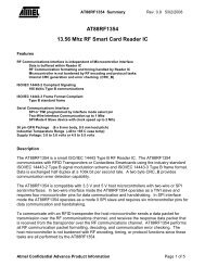
Figure 36 - Fast Opto-Isolated Serial Interface Example<br />
10.0 Disclaimer<br />
© <strong>DLP</strong> Design, Inc., 2002 / 2009<br />
Neither the whole nor any part of the information contained in, or the product described<br />
in this manual, may be adapted or reproduced in any material or electronic form without<br />
the prior written consent of the copyright holder.<br />
This product and its documentation are supplied on an as-is basis and no warranty as to<br />
their suitability for any particular purpose is either made or implied. <strong>DLP</strong> Design, Inc.<br />
will not accept any claim for damages howsoever arising as a result of use or failure of<br />
this product. Your statutory rights are not affected. This product or any variant of it is not<br />
intended for use in any medical appliance, device or system in which the failure of the<br />
product might reasonably be expected to result in personal injury.<br />
This document provides information that may be subject to change without notice.<br />
11.0 Contact Information<br />
<strong>DLP</strong> Design, Inc.<br />
1605 Roma Lane<br />
Allen, TX 75013<br />
Phone: 469-964-8027<br />
Fax: 415-901-4859<br />
E-Mail ( Sales ) : sales@dlpdesign.com<br />
E-Mail ( Support ) : support@dlpdesign.com<br />
Web Site URL : http://www.dlpdesign.com<br />
Rev 1.6 (May 2009)<br />
32<br />
<strong>DLP</strong>-<strong>2232M</strong>-G <strong>DLP</strong> Design, Inc.
<strong>DLP</strong>-<strong>2232M</strong>-G<br />
MODULE<br />
GND<br />
BD3<br />
SI/WUA<br />
AD4<br />
BD0<br />
VCCIOB<br />
AC1<br />
EXTVCC<br />
PORTVCC<br />
GND<br />
AC2<br />
BC1<br />
AD5<br />
AD7<br />
AC3<br />
VCCUSB<br />
AD0<br />
BD7<br />
AD3<br />
GND<br />
BC2<br />
BD2<br />
GND<br />
AD6<br />
GND<br />
BC3<br />
GND<br />
AC0<br />
BD6<br />
RSTOUT#<br />
BC0<br />
AD1<br />
BD4<br />
BD1<br />
VCCIOA<br />
RSTIN#<br />
BD5<br />
SI/WUB<br />
AD2<br />
VCCSW<br />
EXTVCC<br />
BC2<br />
SI/WUB<br />
BC1<br />
BD6<br />
BC0<br />
BC3<br />
BD0<br />
PORTVCC<br />
VCCIOB<br />
BD7<br />
BD3<br />
VCCSW<br />
BD1<br />
BD5<br />
BD4<br />
BD2<br />
VCCIOA<br />
AC2<br />
SI/WUA<br />
GND<br />
AD4<br />
AD3<br />
AD0<br />
AD5<br />
AD6<br />
AD1<br />
AD7<br />
RSTOUT#<br />
AC0<br />
AC1<br />
AD2<br />
AC3<br />
VCCUSB<br />
VCCUSB<br />
VCCUSB<br />
RSTIN#<br />
CN1<br />
CN-USB<br />
1<br />
2<br />
3<br />
4<br />
5<br />
FB1<br />
Ferrite Bead<br />
1 2<br />
C14<br />
.1uF<br />
C3<br />
10uF<br />
R1<br />
470<br />
C16 47pF<br />
R2<br />
27<br />
R3<br />
27<br />
C1<br />
.01uF<br />
R4 1.5K<br />
Y1<br />
6MHz<br />
C12 .033uF<br />
U1<br />
93C56<br />
1<br />
2<br />
3<br />
4<br />
8<br />
7<br />
6<br />
5<br />
CS<br />
SK<br />
DIN<br />
DOUT<br />
VCC<br />
NC<br />
NC<br />
GND<br />
R5 10K R6 2.2K<br />
R7<br />
2.2K<br />
FB2<br />
Ferrite Bead<br />
1 2<br />
Q1<br />
IRLML6402<br />
R8<br />
47K<br />
U2<br />
FT2232D<br />
5<br />
44<br />
4<br />
48<br />
1<br />
2<br />
45<br />
9<br />
18<br />
47<br />
6<br />
46<br />
42<br />
3<br />
8<br />
7<br />
43<br />
24<br />
23<br />
22<br />
21<br />
20<br />
19<br />
17<br />
16<br />
15<br />
13<br />
12<br />
11<br />
10<br />
40<br />
39<br />
38<br />
37<br />
36<br />
35<br />
33<br />
32<br />
30<br />
29<br />
28<br />
27<br />
26<br />
41<br />
25<br />
34 14<br />
31<br />
RSTOUT#<br />
XTOUT<br />
RESET#<br />
EECS<br />
EESK<br />
EEDATA<br />
AGND<br />
GND<br />
GND<br />
TEST<br />
3V3OUT<br />
AVCC<br />
VCC<br />
VCC<br />
USBDM<br />
USBDP<br />
XTIN<br />
AD0<br />
AD1<br />
AD2<br />
AD3<br />
AD4<br />
AD5<br />
AD6<br />
AD7<br />
AC0<br />
AC1<br />
AC2<br />
AC3<br />
SI/WUA<br />
BD0<br />
BD1<br />
BD2<br />
BD3<br />
BD4<br />
BD5<br />
BD6<br />
BD7<br />
BC0<br />
BC1<br />
BC2<br />
BC3<br />
SI/WUB<br />
PWREN<br />
GND<br />
GND VCCIOA<br />
VCCIOB<br />
C17 47pF<br />
C6<br />
47pF<br />
C13 .01uF<br />
C9<br />
.1uF<br />
C18<br />
.1uF<br />
C10<br />
10uF<br />
C7<br />
47pF<br />
JP5<br />
CONN PCB 20x2<br />
8<br />
7<br />
6<br />
1<br />
2<br />
3<br />
4<br />
5<br />
10<br />
9<br />
12<br />
11<br />
13<br />
15<br />
14<br />
17<br />
16<br />
18<br />
20<br />
19<br />
36<br />
35<br />
34<br />
33<br />
32<br />
31<br />
30<br />
29<br />
28<br />
27<br />
26<br />
25<br />
24<br />
23<br />
22<br />
21<br />
37<br />
38<br />
39<br />
40<br />
C4<br />
.1uF<br />
C8<br />
.1uF<br />
C15<br />
.1uF<br />
C5<br />
.033uF<br />
C2<br />
.1uF C11 .1uF