PRO COMP SUSPENSION Part # 51099 Chevrolet ... - Pro Comp Tires
PRO COMP SUSPENSION Part # 51099 Chevrolet ... - Pro Comp Tires
PRO COMP SUSPENSION Part # 51099 Chevrolet ... - Pro Comp Tires

You also want an ePaper? Increase the reach of your titles
YUMPU automatically turns print PDFs into web optimized ePapers that Google loves.
2360 Boswell Road<br />
Chula Vista, CA 91914<br />
Phone 619.216.1444<br />
Fax 619.216.1474<br />
E-Mail tech@explorerprocomp.com<br />
<strong>PRO</strong> <strong>COMP</strong> <strong>SUSPENSION</strong><br />
Suspension Systems that Work!<br />
<strong>Part</strong> # <strong>51099</strong><br />
<strong>Chevrolet</strong> / GMC 1/2 Ton 4X4<br />
1999 - 2006 Silverado / Sierra<br />
This document contains very important information that includes warranty information and instructions<br />
for resolving problems you may encounter. Please keep it in the vehicle as a permanent record.
INSTALLATION<br />
INSTRUCTIONS<br />
Important Note:<br />
<strong>51099</strong><br />
Revised<br />
1.5.06<br />
♦<br />
Vehicles equipped with a 246 transfer case (Auto-trac) will require a replacement CV style front<br />
drive shaft. <strong>Pro</strong> <strong>Comp</strong> offers two CV style front drive shafts.<br />
<strong>Part</strong> Number 52246, Extreme duty shaft with a permanently installed front transfer case output<br />
shaft.<br />
OR<br />
<strong>Part</strong> Number 51246, Standard duty shaft with the slip shaft installed on the drive shaft.<br />
Both drive shafts replace the 29.625” (cap centerline to cap centerline) OEM drive shafts.<br />
NOTE: 2004 models with traction control and Borg Warner transfer case 4482 may<br />
require pro comp driveshaft 51246 to be shortened by 1”. Driveshaft modifications<br />
should only be performed by a certified driveline shop.<br />
Please note that while every effort is made to ensure that the installation of your <strong>Pro</strong> <strong>Comp</strong> lift kit is a positive<br />
experience, variations in construction and assembly in the vehicle manufacturing process will virtually ensure<br />
that some parts may seem difficult to install. Additionally, the current trend in manufacturing of vehicles results<br />
in a frame that is highly flexible and may shift slightly on disassembly prior to installation. The use of pry bars<br />
and tapered punches for alignment is considered normal and usually does not indicate a faulty product. However,<br />
if you are uncertain about some aspect of the installation process, please feel free to call our tech support department<br />
at the number listed on the cover page. We do not recommend that you modify the <strong>Pro</strong> <strong>Comp</strong> parts in any<br />
way as this will void any warranty expressed or implied by the <strong>Pro</strong> <strong>Comp</strong> Suspension company.<br />
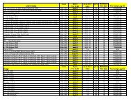
<strong>Part</strong> List:<br />
Box 1 of 5-PN <strong>51099</strong>-1<br />
<strong>Part</strong> # Description Qty. Illus. Page<br />
13-90087 9/16” U-BOLT 4 15 18<br />
20-65302 HARDWARE PACK<br />
13-30330 9/16” FLAT WASHER 8 15 18<br />
13-10423 9/16” HIGHNUT 8 15 18<br />
90-1450 FRONT CROSS MEMBER 1 7, 8, 9 13, 14, 15<br />
90-1496 SWAY BAR SPACER 2 10 15<br />
90-2144 BUMP STOP SPACER 2 14 18<br />
90-2202 DIFFERENTIAL TORQUE TUBE 1 5 10<br />
90-6158 HARDWARE PACK<br />
90-2055 1/2” ID X 1 1/2” OD X 3/8” SPACER 2 7 13<br />
90-2014 SPACER, 3/4” OD X 1/2” ID X 1/4” 2 9 15<br />
90-4053 5/8” COUPLER 2 7, 9 13, 15<br />
96-4036 STEERING CONE REDUCER 4 7 13<br />
90-6173 HARDWARE PACK<br />
70-0372251543 3/8” X 2 1/4” NC SOCKET HEAD CAP SCREW 4 10 15<br />
73-03700034 3/8” SAE GR 8 FLAT WASHER 8 10 15<br />
72-03700100816 3/8” NC SELF LOCKING NUT 4 10 15<br />
70-0503751800 1/2” X 3 3/4” NC GR 8 HEX BOLT 2 7, 10 13, 15<br />
73-05000038 1/2” GR 8 AN FLAT WASHER 10 7 13<br />
2
<strong>Part</strong> # Description Qty. Illus. Page<br />
70-0624501800 5/8” X 4 1/2” NC GR 8 HEX BOLT 2 8 14<br />
73-06200034 5/8” SAE GR 8 FLAT WASHER 4 8 14<br />
72-06200100816 5/8” NC SELF LOCKING NUT 2 8 14<br />
70-0502751800 1/2” X 2 3/4” NC GR 8 HEX BOLT 2 7 13<br />
73-05000034 1/2” GR 8 FLAT WASHER 4 7 13<br />
72-05000100816 1/2” NC SELF LOCKING NUT 4 7 13<br />
95-400 CAST IRON LIFT BLOCK 2 15 18<br />
96-1505 WELD PLATE 1 1 8<br />
90-6303 HARDSWARE PACK: FRONT BRAKE LINE 1<br />
90-1868 FRONT BRAKE LINE DROP 2<br />
90-6299 HARDWARE PACK 1<br />
90-6189 HARDWARE PACK: DIFF VENT 1<br />
Box 2 of 5-PN <strong>51099</strong>-2<br />
90-1435 <strong>COMP</strong>RESSION STRUT MOUNT 2 11,12 17<br />
90-1446 DIFFERENTIAL DROP, DRIVER SIDE 1 5 10<br />
90-1447 DIFFERENTIAL DROP, PASSENGER SIDE 1 6 11<br />
90-6223 HARDWARE PACK, TORSION DROP ADAPTERS 1<br />
70-0371251800 3/8” X 1 1/4” NM GR 8 HEX BOLT 4 15 18<br />
72-03700100816 3/8” NC SELF LOCKING NUT 4 15 18<br />
73-03700034 3/8” SAE GR 8 FLAT WASHER 8 15 18<br />
90-1635 TORSION BAR DROP, UNIVERSAL BASE 2 14 18<br />
90-1636 TORSION DROP ADAPTER, CHEVY/GMC 02 2 14 18<br />
90-1638 TORSION DROP ADAPTER, CHEVY/GMC 99-01 2 14 18<br />
90-1455 UPPER A-ARM DROP, DRIVER SIDE 1 10 15<br />
90-1466 UPPER A-ARM DROP, PASSENGER SIDE 1 10 15<br />
90-2196 CENTER STEERING LINK 1 7 13<br />
90-6172 HARDWARE PACK<br />
70-0431251800 7/16” X 1 1/4” NC GR 8 HEX BOLT 4 10 15<br />
73-04300034 7/16” SAE GR 8 FLAT WASHER 8 10 15<br />
72-04300100816 7/16” NC SELF LOCKING NUT 4 10 15<br />
70-0561501800 9/16” X 1 1/2” NC GR 8 HEX BOLT 4 10 15<br />
70-0563751800 9/16” X 3 3/4” NC GR 8 HEX BOLT 1 5 10<br />
73-05600034 9/16” SAE GR 8 FLAT WASHER 10 5, 10 10, 15<br />
72-05600100816 9/16” NC SELF LOCKING NUT 5 5, 10 10, 15<br />
70-0501251800 1/2” X 1 1/4” NC GR 8 HEX BOLT 1 5 10<br />
73-05000034 1/2” GR 8 FLAT WASHER 2 5 10<br />
90-6177 HARDWARE PACK<br />
90-2011 1.0” X .5” X 1.5” SPACER 2 13 18<br />
15-11149 TORSION BAR DROP BUSHING 4 13 18<br />
90-6181 HARDWARE PACK, SHOCK ADAPTER<br />
90-1079 SHOCK ADAPTER 2 16 18<br />
70-0502751500 1/2” X 2 3/4” NC GR 8 HEX BOLT 2 16 18<br />
72-05000100512 1/2” NC GR 5 NY-LOCK NUT 2 16 18<br />
72-06200100512 5/8” NC GR 5 NY-LOCK NUT 2 16 18<br />
73-06200032 5/8” USS FLAT WASHER 2 16 18<br />
54314 SHOCK SLEEVE-1/2” X 5/8” X 1.480 “ 2 16 18<br />
Box 3 of 5-PN <strong>51099</strong>-3<br />
90-1459 REAR CROSS MEMBER 1 3, 4, 11 9, 10, 17<br />
90-2126 <strong>COMP</strong>RESSION STRUT 2 11, 12 17<br />
90-6170 HARDWARE PACK<br />
42-778T CAM-BOLT KITS 4 8, 10 14, 15<br />
3<br />
<strong>51099</strong><br />
Revised<br />
1.5.06
<strong>Part</strong> # Description Qty. Illus. Page<br />
90-6174 HARDWARE PACK<br />
70-0371251800 3/8” X 1 1/4” NC GR 8 HEX BOLT 2 14 18<br />
73-03700034 3/8” SAE GR 8 FLAT WASHER 4 14 18<br />
72-03700100816 3/8” NC SELF LOCKING NUT 2 14 18<br />
70-0501251800 1/2” X 1 1/4” NC GR 8 HEX BOLT 2 12 17<br />
70-0504001800 1/2” X 4” NC GR 8 HEX BOLT 4 11, 12 17<br />
73-05000034 1/2” GR 8 FLAT WASHER 10 11, 12 17<br />
72-05000100816 1/2” NC SELF LOCKING NUT 4 11, 12 17<br />
70-0431251800 7/16” X 1 1/4” NC GR 8 HEX BOLT 8 13 18<br />
73-04300034 7/16” SAE GR 8 FLAT WASHER 16 13 18<br />
72-04300100816 7/16” NC SELF LOCKING NUT 8 13 18<br />
90-6175 HARDWARE PACK<br />
70-0625501800 5/8” X 5 1/2” NC GR 8 HEX BOLT 2 8 14<br />
73-06200034 5/8” SAE GR 8 FLAT WASHER 4 8 14<br />
72-06200100816 5/8” NC SELF LOCKING NUT 2 8 14<br />
70-0371251800 3/8” X 1 1/4” NC GR 8 HEX BOLT 6 3 9<br />
73-03700034 3/8” SAE GR 8 FLAT WASHER 14 3 9<br />
72-03700100816 3/8” NC SELF LOCKING NUT 6 3,4 9, 10<br />
70-0561751800 9/16” X 1 1/2” NC GR 8 HEX BOLT 2 6 11<br />
73-05600042 9/16” USS GR 8 FLAT WASHER 2 6 11<br />
73-05600034 9/16” SAE GR 8 FLAT WASHER 2 6 11<br />
72-05600100816 9/16” NC SELF LOCKING NUT 2 6 11<br />
72-03700100512 3/8” NC GR 5 NY-LOCK NUT 2 4 10<br />
90-6179 HARDWARE PACK<br />
15-11148 DIFFERENTIAL MOUNT BUSHING 8 11, 12 17<br />
90-2109 <strong>COMP</strong>RESSION STRUT SLEEVE 4 11, 12 17<br />
90-1476 NUT PLATE-1/2” 3 5, 12 10<br />
15-11018 LOW <strong>PRO</strong>FILE BUMP STOP 2 4 10<br />
90-6275 HARDWARE PACK 1<br />
90-1784 WASHER– 1.650 X .620 X .042 8<br />
Box 4 of 5-PN <strong>51099</strong>-4<br />
929505 ES9000 SHOCKS, REAR 2 16 18<br />
920590 ES9000 SHOCKS, FRONT 2<br />
Box 5 of 5-PN <strong>51099</strong>-5<br />
13125-1 ADD-A-LEAF 2 15 18<br />
97-380 3/8” X 4 1/2” CENTER BOLT 2 15 18<br />
8337-1 3/8” CENTER BOLT LOCK NUT 2 15 18<br />
98-00250-1 2 1/2” SPRING CLAMP 4 15 18<br />
98-00250-2 2 1/2” SPRING PLATE 4 15 18<br />
<strong>51099</strong><br />
Revised<br />
1.5.06<br />
Equipment Available from your <strong>Pro</strong> <strong>Comp</strong> Distributor!<br />
Rear MX-6 Reservoir Shocks:<br />
Also, Check out our outstanding selection of<br />
new installation!<br />
MX6141R<br />
tires to compliment your<br />
4
<strong>51099</strong><br />
Revised<br />
1.5.06<br />
<strong>Pro</strong> <strong>Comp</strong> now offers a full line of All-Terrain and Mud Terrain tires. <strong>Pro</strong> <strong>Comp</strong> also<br />
offers a skid plate, traction bars, light bars and a multiple shock kit for this vehicle.<br />
All product is sold separately. Contact your dealer for details.<br />
Introduction:<br />
♦ This installation requires a professional mechanic!<br />
♦<br />
♦<br />
♦<br />
♦<br />
♦<br />
♦<br />
♦<br />
♦<br />
♦<br />
We recommend that you have access to a GM service manual for your vehicle to assist in the<br />
disassembly and reassembly of your vehicle. It contains a wealth of detailed information.<br />
Prior to installation, carefully inspect the vehicle’s steering and driveline systems paying close<br />
attention to the tie rod ends, ball joints, wheel bearing preload, pitman and idler arm. Additionally,<br />
check steering-to-frame and suspension-to-frame attaching points for stress cracks. The overall<br />
vehicle must be in excellent working condition. Repair or replace all worn or damaged parts!<br />
Read the instructions carefully and study the illustrations before attempting installation! You may<br />
save yourself a lot of extra work.<br />
Check the parts and hardware against the parts list to assure that your kit is complete. Separating<br />
parts according to the areas where they will be used and placing the hardware with the brackets before<br />
you begin will save installation time.<br />
Check the special equipment list and ensure the availability of these tools.<br />
Secure and properly block vehicle prior to beginning installation.<br />
ALWAYS wear safety glasses when using power tools or working under the vehicle!<br />
Use caution when cutting is required under the vehicle. The factory undercoating is flammable.<br />
Take appropriate precautions. Have a fire extinguisher close at hand.<br />
Foot pound torque readings are listed on the Torque Specifications chart at the end of the<br />
instructions. These are to be used unless specifically directed otherwise. Apply Loctite retaining<br />
compound where specified.<br />
Please Note:<br />
♦ Front end realignment is necessary.<br />
♦<br />
♦<br />
Speedometer and ABS recalibration is necessary if larger tires (10% more than stock diameter) are<br />
installed<br />
This system utilizes the stock torsion bars which normally afford the best ride quality. If, after kit is<br />
installed, ride or handling seems too “soft”, heavier Gross Vehicle Weight Rating (GVWR) bars can be<br />
installed. GM offers various bars for up to 10,000 lbs. GVWR.<br />
5
♦<br />
♦<br />
♦<br />
<strong>51099</strong><br />
Revised<br />
1.5.06<br />
Due to differences in manufacturing, dimensions and inflated measurements, tire and wheel combinations<br />
should be test fit prior to installation. Tire and wheel choice is crucial in assuring proper fit, performance,<br />
and the safety of your <strong>Pro</strong> <strong>Comp</strong> equipped vehicle. For this application, a wheel not to exceed<br />
8” in width with a minimum backspacing of 4” must be used. Additionally, a quality tire of radial<br />
design, not exceeding 35” tall X 12.5” wide is recommended. Please note that the use of a 35” X 12.5”<br />
tire may require fender modification. Violation of these recommendations will not be endorsed as acceptable<br />
by <strong>Pro</strong> <strong>Comp</strong> Suspension and will void any and all warranties either written or implied.<br />
2005 trucks require a 17” wheels to clear the calipers.<br />
If your truck has a tire pressure sensors on the factory wheels please contact the wheel manufactures<br />
for proper installation and removal.<br />
Front disassembly:<br />
Ensure that your work space is of adequate size and the work surface is level. Place the vehicle in<br />
neutral. Place your floor jack under the front cross member and raise vehicle. Place jack stands under<br />
the frame rails behind the front wheel wells and lower the frame onto the stands. Remove the jack and<br />
place the vehicle back in gear, set the emergency brake, and place blocks both in front and behind the<br />
rear wheels.<br />
Note: A special puller tool is required for safe removal and installation of the torsion adjuster arms. This<br />
special puller can be purchased from you local GM dealer (Tool #J36202) or from Kent Moore Tool<br />
Group in Roseville, MI. (800) 345-2233 or (313) 774-9500 (<strong>Part</strong> #J22517-C). You may be able to rent<br />
one of these tools at your local parts store. Refer to the GM service manual for more information.<br />
WARNING:<br />
Be extremely careful when loading or unloading the torsion bars! There is a tremendous amount<br />
of stored energy in the bars. Keep your hands and body clear of the adjuster arm assembly and<br />
puller tool in case anything slips or breaks! Remember your safety glasses!<br />
1. If there are factory skid plates installed, remove them.<br />
2. Measure torsion bar adjusting screw depth and record this dimension for later use when replacing the<br />
torsion adjuster arm on reassembly. Remove the torsion bar adjusting screw. Apply a small amount of<br />
lubrication grease to the puller threads and the puller shaft-to-adjuster arm contact point. Load puller<br />
and torsion adjuster arm until the adjuster nut can be removed from the cross member. Release the<br />
puller to unload the torsion bar. With the bar unloaded, slide it forward into the lower control arm until<br />
the adjuster arm falls free. If the bar seems stuck, use a hammer and punch through the hole in the<br />
rear of the cross member to dislodge it. Repeat this procedure on the other side of the vehicle.<br />
3. Remove the torsion bar cross member by removing the through bolts on each side of the vehicle. With<br />
the cross member out of the way, the torsion bars can be pulled from the lower control arms and<br />
removed. Mark the torsion bars as to their orientation (left side, right side, and front). They must be<br />
reinstalled exactly as removed! Save these nuts and bolts for reuse on reassembly.<br />
4. Disconnect the ABS sensor wire and position it out of the way to prevent damage to the wiring or<br />
connector ends. Remove brake caliper assembly and securely fasten it away from the work area.<br />
Steps 5 through 12 are performed one side at a time:<br />
5. Remove the 6 bolts that attach the CV axle to the differential. Save these for reuse.<br />
6
6. Detach the outer end of the tie rod from the spindle assembly. Special tools are available to safely<br />
remove these without damage to the joint or the protective boot. Your GM service manual has details<br />
on this procedure<br />
7. Remove the anti-sway bar links that connect the sway bar to the lower A-arm. Save this hardware for<br />
reuse on reassembly.<br />
8. Remove the shock absorber mounting bolts from the lower A-arm. Save this hardware for reuse.<br />
9. Remove the upper and lower A-arm pivot nuts. Save this hardware for reuse on reassembly.<br />
7<br />
<strong>51099</strong><br />
Revised<br />
1.5.06<br />
10. Support the A-arm assembly and carefully remove the pivot bolts. Lower the assembly to the floor and<br />
set aside. This assembly is relatively heavy and not a rigid assembly. Be very careful when removing.<br />
Save the pivot bolts for reuse.<br />
11. Remove the upper shock nuts and remove the stock shock absorbers. Discard these parts.<br />
12. Detach the front drive shaft from the differential yolk and secure it out of the way. Disconnect the<br />
electronic sensor and vent line from the differential and secure them out of the way.<br />
13. Remove the factory bump stops by using a large channel lock type of pliers and discard the stops.<br />
14. Remove drag link from the pitman arm and idler arm. It may be easier to remove the Idler arm from the<br />
frame with the drag link. Set this assembly aside. Save the nuts for reuse.<br />
15. Remove the front differential lower mounting bolt. Save this nut and bolt for reuse.<br />
16. Remove the passenger side differential mounting bolts. Save this hardware for reuse.<br />
17. Remove the differential cross member and discard this hardware.<br />
18. While supporting the differential, remove the upper mount bolt and carefully lower the differential to the<br />
ground. Retain this nut and bolt for reuse on reassembly.<br />
19. Using a 2” hole saw without the pilot drill, remove the bump stop mount from the frame on each side of<br />
the vehicle. It is important that you do NOT remove any more material than you have to. Do NOT drill<br />
through this pad with the hole saw!<br />
20. Using an angle grinder or equivalent, remove any remaining weld from this area to achieve a smooth<br />
surface.<br />
21. Using a reciprocating saw or other suitable saw, on the driver side A-arm pocket / differential mount,<br />
cut the rear section out as shown in Illustration A and to the dimensions shown in Illustration 1.<br />
22. On the passenger side mount, cut a 45º section from the pocket as per Illustration 2.<br />
23. On the OEM bump stop flanges on both sides of the truck, cut the front corners to allow for shock<br />
clearance. See Illustration 3.<br />
24. On the front upper A-arm mount pockets, knock the existing alignment cam pins off with a hammer and<br />
grind the surface smooth.<br />
25. Install the provided replacement bump stops (PN 15-11018) to the main cross member as indicated in<br />
Illustration 4. It is important that this is done now as it is not possible to install these stops after<br />
installation of the cross member.
<strong>51099</strong><br />
Revised<br />
1.5.06<br />
Illustration A<br />
A1+A2<br />
Drivers Side<br />
OEM<br />
A1<br />
Front of vehicle<br />
A2<br />
Front of vehicle<br />
Illustration 1<br />
Drivers side.<br />
Illustration 2<br />
Passenger side.<br />
Front of vehicle<br />
PN 96-1505<br />
Remove to<br />
clear<br />
8
9<br />
<strong>51099</strong><br />
Revised<br />
1.5.06<br />
26. With the differential out of the vehicle, temporarily mount the main cross member (PN 90-1459) to the<br />
frame using the existing lower A-arm pockets and OEM bolts. Make sure that the cross member is<br />
located with the inside face of the rear flange even with the rear edge of the OEM bump stop flange as<br />
indicated in Illustration 3 (the driver side should look the same as the passenger side when properly<br />
located). When the location is set, clamp the cross member to the flanges to prevent movement and<br />
drill the 2 upper mount holes through the OEM flange on both sides of the truck. The bottom hole is not<br />
accessible with a drill at this time, it must be marked for later drilling. Install provided 3/8” X 1 1/4” NC<br />
bolts, washers and Stover nuts and tighten to prevent movement. Repeat this step on the passenger<br />
side of the truck. On the driver side, tighten up the bottom OEM through bolts until there is about 1/16”<br />
clearance between the cross member and factory pocket sides. Place the supplied 1/8” X 3 1/2” X 4”<br />
plate (PN 96-1505) across the cutout at the rear of the pocket, trim if needed and tack weld this piece<br />
in place. These welds must be sufficiently strong to withstand the removal of the cross member for the<br />
next steps.<br />
27. Remove the rear cross member. Finish welding the replacement plate to the back of the pocket. Drill<br />
the remaining 3/8” holes through the OEM flanges on both sides of the vehicle. It is important that<br />
these bolts are used. Do not skip this step.<br />
28. Install the differential lowering shackle (PN 90-1446) into the OEM location with the original nut and<br />
bolt. See Illustration 5.<br />
29. Install the<br />
passenger side<br />
spacer bracket<br />
(PN 90-1447) to<br />
the OEM mount<br />
using the original<br />
hardware. The<br />
bracket is slightly<br />
tapered. The<br />
narrow end of the<br />
taper is oriented<br />
to the rear of the<br />
truck. Tighten<br />
OEM fasteners to<br />
specifications.<br />
Illustration 6.<br />
30. Hang the<br />
differential from<br />
the shackle using<br />
the supplied 9/16”<br />
X 3 3/4” bolt,<br />
washers, and nut.<br />
Insert the bolt<br />
from the center of<br />
the truck to the<br />
outside and install<br />
Front of vehicle<br />
Important!<br />
See note 27.<br />
PN 90-1459<br />
3/8” X 1 1/4”<br />
3 places per side<br />
Illustration 3<br />
Passenger side.<br />
See note 24.<br />
This hole must be<br />
drilled with the cross<br />
member removed.<br />
See note 28
<strong>51099</strong><br />
Revised<br />
1.5.06<br />
the supplied torque strut as shown in<br />
Illustration 5. Install the supplied washer and<br />
lock nut and tighten the assembly enough so<br />
that the strut can be moved without much effort<br />
to complete step 33.<br />
31. Attach the differential to the passenger side<br />
spacer bracket as shown in Illustration 6. Use<br />
the supplied 9/16” X 1 3/4” bolts, 2 SAE<br />
washers, 2 USS washers, and nuts. The USS<br />
washers go onto the slotted aluminum flange of<br />
the differential. At this point leave the fasteners<br />
slightly loose until the main cross member is<br />
back in place and the torque strut is positioned.<br />
Front of vehicle<br />
PN 15-11018<br />
Illustration 4<br />
Passenger side.<br />
32. Rotate the differential torque strut up and to the rear until it is at its closest point to the truck frame as<br />
shown in Illustration 5. Mark the location of the hole. After marking this location, rotate the strut out of<br />
the way and drill this hole to clear a 1/2” bolt. Rotate the strut back into place and install the supplied<br />
1/2” X 1 1/4” bolt through the strut and through the frame member. A 1/2” nut plate (PN 90-1476) is<br />
supplied to facilitate this installation, position this nut plate over the bolt on the inside of the A-arm<br />
pocket and start the bolt by hand. Leave all hardware loose until the completion of the cross member<br />
installation.<br />
33. Reinstall the rear cross member into the truck using the OEM bolts to hold it in place. Install these<br />
bolts with the threads pointing away from the CV joints. Make sure to carefully guide the differential<br />
mounting bushing into it’s mounting flange on the new cross member. Install the OEM bolt through the<br />
cross member and differential bushing with the threads to the outside of the truck and install the OEM<br />
nut. Finish installing the 3/8” nuts, bolts, and washers to the upper flange mounts on both sides of the<br />
vehicle and torque all cross member hardware to specifications on page 21. Also tighten the<br />
differential mounting hardware to specifications at this time.<br />
34. Using the differential drop<br />
extension pack (PN 90-<br />
6189) fit the new hose to<br />
the differential. Place the<br />
supplied plug in the end of<br />
the tube and connect the<br />
factory tube to it.<br />
35. Install the <strong>Pro</strong> <strong>Comp</strong>.<br />
center link drop (PN 90-<br />
2196) to the pitman arm<br />
and idler arm using the<br />
factory nuts. See<br />
Illustration 7. When<br />
properly installed, the drop<br />
is perpendicular to the<br />
ground.<br />
OEM bolt and nut<br />
9/16” X 3 3/4”<br />
PN 90-1446<br />
PN 90-2202<br />
Illustration 5<br />
Driver side.<br />
Front of vehicle.<br />
1/2” X 1 1/4”<br />
PN 90-1476<br />
10
36. Mount the front cross member to the existing front, lower A-arm pockets with the OEM bolts and nuts.<br />
Tighten to specs. Using the cross member as a guide, drill through the factory frame material at this<br />
time. See hi-lighted note in Illustration 7 for the location.<br />
<strong>51099</strong><br />
Revised<br />
1.5.06<br />
37. Loosely install the OEM center link to the center link drop, with the bends to the rear, using the supplied<br />
1/2” X 3 3/4” Bolts and other hardware supplied as indicated in Illustration 7. Leave the lock nuts loose<br />
for the moment. Follow this illustration<br />
exactly!<br />
38. Install the rod end guide (PN 90-4053)<br />
assemblies to the front cross member as<br />
shown in Illustrations 7 & 9. Use the<br />
supplied 1/2” X 2 3/4” bolts, spacers,<br />
washers, and nuts. Place the ends of the<br />
rod ends onto the ends of the drop link<br />
bolts. Snug up the bolt assemblies and<br />
rotate the steering assembly back and<br />
forth several times to check for clearance.<br />
Additional washers are supplied to<br />
facilitate the correction of any<br />
misalignment issues you may encounter.<br />
It is very important to ensure no binding<br />
occurs throughout the entire range of<br />
motion of the steering assembly. Once<br />
correct clearances are established.<br />
Torque all fasteners to specifications.<br />
39. At this point, if you have purchased the<br />
optional dual shocks, install the kit per<br />
the enclosed instructions before<br />
proceeding to the next step. Leave all<br />
hardware loose, and leave the front<br />
mount through bolt out until the next<br />
step is complete.<br />
PN 90-1447<br />
Front of vehicle.<br />
OEM hardware<br />
Illustration 6<br />
Passenger side.<br />
USS washers<br />
9/16” X 1 3/4”<br />
40. Drill out the sway bar mounting threads to clear 3/8” bolts (13/32”). At the front of the OEM A-arm stop,<br />
it will be necessary to grind the existing droop stop tab back enough to clear the new PN 90-1466<br />
hardware. See Illustration 8. Install the front, upper A-arm drops to the existing upper pockets using<br />
the supplied 9/16” X 1 1/2” bolts (if installing with the above mentioned shock kit, install using the 9/16”<br />
through bolt supplied with the shock kit) and the 7/16” X 1 1/4” bolts, washers, and nuts from the<br />
bottom of the adapter through the existing holes in the OEM frame. The back holes in the adapter<br />
must be drilled as indicated on Illustration 9. Leave slightly loose until the sway bar is installed to<br />
assure easy insertion of the sway bar mounting hardware.<br />
40. The factory sway bar is remounted upside down using the OEM bushings and mounts. The mounts<br />
are to the original location with spacer (PN 90-1496), supplied 3/8” X 2 1/4” socket head cap screws,<br />
washers, and lock nuts. See Illustration 9. Tighten the bushing bolts enough to keep the sway bar<br />
from swinging but loose enough to facilitate the installation of the end links.<br />
11
12<br />
<strong>51099</strong><br />
Revised<br />
1.5.06<br />
41. Assemble the compression strut bushings and sleeves into the struts as shown in Illustrations 11 & 12<br />
using the components in part pack # 90-6179.<br />
42. Position the compression struts (PN 90-2126) into the tabs on the front cross member using the<br />
supplied 1/2” X 4” bolts, washers, and nuts. See Illustration 11. The strut end with the eyes welded at<br />
an angle go to the front, the struts are angled to the outside of the vehicle. Loosely place the<br />
compression strut mounts (PN 90-1435) onto the transmission cross member using the supplied 1/2” X<br />
1 1/4” bolts, washers, and tab nuts. See Illustration 12. The location of the rear saddle is dependant<br />
on the transmission option in your vehicle. Swing one compression strut up to its previously installed<br />
mount and position the mount to ensure easy insertion of the mounting cross bolts. You may have to<br />
rotate the saddle or use the other hole (or slot) to achieve a satisfactory fit. Swing the strut back out of<br />
the way and torque the rear strut mount bolt to specifications being careful to maintain its position.<br />
Repeat this procedure for the other side. Reinstall the struts with the remaining 1/2” X 4” bolts,<br />
washers, and nuts and torque all to specifications.<br />
43. At this point, check all mounting hardware and adapters for correct fit and check all fasteners to make<br />
sure they are in place and correctly tightened.<br />
44. Install the A-arm assemblies on each side of the vehicle by reversing the disassembly order. Attach<br />
the lower A-arm using the supplied 5/8” X 5 1/2” to the rear, 5/8” X 4 1/2” bolts to the front, washers<br />
and nuts. The upper A-arms are installed using the supplied new alignment cam (PN 42-778T)<br />
assemblies. They are installed with the threads away from the center of the A-arm. Be careful not to<br />
damage the ABS sensor wire. DO NOT tighten the pivot bolts at this time. For correct positioning of<br />
the rubber bushings, the vehicle should be fully on the ground before these bolts are torqued to<br />
specifications.<br />
Note: If there is excessive space between the upper a arm and the new cross member, shim the space out<br />
with the contents of an 90-6275.<br />
45. Install the factory half shafts to the differential with the OEM bolts. Torque to specifications.<br />
46. Install the sway bar link to the sway bar and lower A-arm with the OEM links. Tighten until the<br />
bushings just start to bulge out. Do not over tighten!<br />
47. Install the front <strong>Pro</strong> <strong>Comp</strong> shock absorber (PN 920590) to the original position using PN 90-1079 for<br />
the upper mount and the OEM bolts and nuts for the bottom mount.<br />
48. Install the front drive shaft to the differential.<br />
49. Install the tie rod ends to the steering knuckle and torque to factory specifications.<br />
50. Carefully install the front caliper assemblies to each side of the truck.<br />
51. Remove the factory brake line brackets from the frame. Using the supplied brackets (PN 90-1868) and<br />
the previously removed factory bolt attach the new bracket in place of the stock bracket with the bends<br />
facing down. Attach the stock brake line bracket to the new bracket using the new hardware (PN 90-<br />
6299).<br />
52. Install the ABS sensor wiring and secure them to the brake lines with “zip-ties”. Again, the harness<br />
must be routed to prevent breakage or chaffing. Move the A-arm assembly up and down to its limits<br />
several times to check for binding and to ensure that there are no interference or pinching problems<br />
with the brake lines and ABS wiring.
Illustration 7<br />
<strong>51099</strong><br />
Revised<br />
1.5.06<br />
Pitman arm<br />
Front of vehicle.<br />
Idler arm<br />
PN 90-2196<br />
See note 35. This<br />
hole must be drilled.<br />
1/2” X 3 3/4”<br />
PN 90-4036<br />
PN 90-1450<br />
PN 90-2055<br />
OEM hardware<br />
Rod End Guides<br />
1/2” AN washer<br />
1/2” X 2 3/4”<br />
See detail illustration 9<br />
13
<strong>51099</strong><br />
Revised<br />
1.5.06<br />
Illustration 8<br />
Passenger Side View<br />
Cam bolt kits<br />
PN 42-778T<br />
2 per side<br />
OEM Bolt<br />
5/8” X 5 1/2”<br />
See note 39<br />
9/16” X 1 1/2”<br />
2 per side<br />
5/8” X 4 1/2”<br />
PN 90-1466 passenger side<br />
PN 90-1455 driver side<br />
14
Front of vehicle<br />
Coupler assembly<br />
PN 90-4053<br />
<strong>51099</strong><br />
Revised<br />
1.5.06<br />
Illustration 9<br />
Passenger side.<br />
PN 90-2014<br />
See note 39. This<br />
hole must be drilled.<br />
Use 7/16” X 1 1/4”<br />
bolts.<br />
Illustration 10<br />
Passenger side shown.<br />
Front of vehicle<br />
9/16” X 1 1/2”<br />
2 places.<br />
PN 90-1496<br />
PN 90-1455 Driver<br />
PN 90-1466 Passenger<br />
3/8” X 2 1/4”<br />
2 places.<br />
15
<strong>51099</strong><br />
Revised<br />
1.5.06<br />
53. Install the torsion bar cross member drops by locating the new parts (PN 90-1435) in place as shown in<br />
Illustrations 13, 14, 15, & 16, and clamping them in place to the bottom and face of the frame rail.<br />
The location is determined by centering the new adapter holes around the OEM mounting rivets as<br />
shown in the detail views. Drill the four mounting holes per side for clearance of 7/16” bolts. Using the<br />
supplied 7/16” X 1 1/4” bolts, fasten the drops to the frame rails and torque to specifications.<br />
54. From the factory, there are at least two different configurations for the torsion drop brackets. Included in<br />
the kit are adapters made specifically for these differences. The primary difference between the cross<br />
members is the width. Models with a torsion cross member width of 40 1/2” (bolt center to bolt center)<br />
will use torsion drop adapters PN 90-1638. cross members with a width of 39” will use PN 90-1636.<br />
they are mounted to the universal adapters previously installed using four 3/8” X 1 1/4” bolts from parts<br />
pack PN 90-6223.<br />
55. Install the Torsion bars by reversing the order in which they were removed. Again, be very careful to<br />
install them with the same orientation that they were removed (I.E. left front to left front, right front to<br />
right front)! Reset the preload bolts to the same measurements previously taken.<br />
56. With the truck still on jack stands and the suspension hanging at full extension, cycle the steering from<br />
lock to lock to check that all components have clearance and operate freely. Pay very close attention<br />
to the ABS wiring and brake lines.<br />
57. Lower the truck to the ground to preload the suspension and unload the upper A– arms. Tighten the<br />
lower A-arm pivot bolts to specifications. It is necessary to rotate the upper A-arm alignment cam bolts<br />
to a neutral position (in the center of the alignment slot) and then tighten the cam bolts to<br />
specifications. This step is necessary to allow you to get to a professional alignment shop only! Do not<br />
assume that this setting is “close enough” and skip the alignment.<br />
FRONT BRAKE LINE<br />
BRACKET<br />
16
<strong>51099</strong><br />
Revised<br />
1.5.06<br />
Illustration 11<br />
Rear cross member<br />
Rear Cross member<br />
PN 90-1459<br />
Urethane bushings<br />
PN 15-11148<br />
4 per strut<br />
Steel sleeve<br />
PN 90-2109<br />
1/2” X 4” bolts<br />
2 per strut<br />
1/2” X 4” bolts<br />
2 per strut<br />
<strong>Comp</strong>ression<br />
strut rear mount<br />
PN 90-1435<br />
<strong>Comp</strong>ression<br />
struts<br />
PN 90-2126<br />
Nut plate<br />
PN 90-1476<br />
17<br />
Illustration 12<br />
Transmission mount
<strong>51099</strong><br />
Revised<br />
1.5.06<br />
Illustration 13<br />
Illustration 14<br />
7/16” X 1 1/4”<br />
PN 90-1635<br />
PN 90-1635<br />
PN 90-1636<br />
3/8” X 1 1/4”<br />
PN 90-1638<br />
PN 90-2012<br />
PN 15-11149<br />
OE Bolt<br />
Illustration 15<br />
Drivers Side.<br />
Illustration 16<br />
<strong>Comp</strong>lete, Drivers Side.<br />
18
Rear kit installation<br />
<strong>51099</strong><br />
Revised<br />
1.5.06<br />
1. Raise the rear of the truck enough for the tires to clear the ground and use jack stands on the frame to support<br />
the truck. Remove the rear tires and wheels.<br />
2. Carefully remove the OEM shock absorbers. It may be necessary to raise the differential housing slightly to<br />
facilitate their removal.<br />
3. One side at a time, support the differential housing on the side being modified. Remove the “U” bolts from that<br />
axle end and discard. Carefully lower the differential away from the OEM springs. Remove and discard the<br />
OEM riser block from its mount pad. Take careful note of the position of the factory spring packs.<br />
4. ADD-A-LEAF (13125-1) INSTALLATION NOTE: In order to properly install the add-a-leaf spring, it will be<br />
necessary to contain the elasticity in the leaf spring with “C” clamps when the center bolt is removed.<br />
Some springs have a factory helper spring consisting of one or more flat leaves installed at the bottom<br />
of the leaf pack. DO NOT install the add-a-leaf spring in or below the helper spring.<br />
5. Hold the spring assembly securely together with “C” clamp. If necessary remove any spring leaf alignment<br />
clamps. Remove the spring center bolt. A hammer and drift punch may be used to drive it out if necessary.<br />
6. Carefully remove “C” clamps and lay unassembled leaves aside.<br />
NOTE: Add-a-leaf will be placed in the spring assembly progressively according to length. For<br />
example, if the existing leaves are 32” long and 25” long and the add-a-leaf is 28” long, place the add-aleaf<br />
between the existing leaves.<br />
7. Apply a small amount of grease to the end of the add-a-leaf, place it in the spring assembly as described in the<br />
note above, and reassemble the leaf springs using the “C” clamps also insert the new center bolt 97-380 and<br />
torque the center bolt nut to 20 ft./lbs. With a hacksaw, cut the center bolt even with the top of the nut.<br />
8. Loosely assemble the complete spring assemblies into their respective axle mounts. As shown in<br />
ILLUSTRATION 19, place the 95-400 blocks in position. Make sure the pin in the block is in the hole of the axle<br />
housing spring pad. The short end of the block goes toward the front of the vehicle. Install the block so the<br />
pinion moves up.<br />
9. If you are installing an optional traction bar kit, install the riser block as is. If you are not using the traction bars, it<br />
will be necessary to grind off approximately 1/4” of the locating dowel. Make sure after grinding that you test fit<br />
the riser block to ensure it fits the axle housing without interfering with the axle tube. Install the new 4” riser<br />
block, short end to the front, to the mount pad on the axle housing and raise the axle housing until the riser block<br />
hole fits around the new leaf spring center bolt.<br />
10. Install the new “U” bolts over the leaf spring assembly and using the new washers and nuts supplied along with<br />
the existing spring plates, torque the U-bolt nuts to 105 ft./lbs. See Illustration 19.<br />
11. Repeat these steps on the other side of the vehicle.<br />
12. Remove the factory bump stops and install the bump stop extensions provided (PN 90-2144). See Illustration<br />
17.<br />
13. Before installing your new <strong>Pro</strong> <strong>Comp</strong> shock absorbers, it is necessary that you check for adequate clearance.<br />
Temporarily install your <strong>Pro</strong> <strong>Comp</strong> shocks into the shock mounts. Carefully check for clearance issues. If there<br />
are areas that come in contact with or are very close to your new shocks, carefully remove sufficient material to<br />
ensure trouble free operation. Pay particular attention to the area around the lower shock mount. When all<br />
clearance issues have been resolved, install your new <strong>Pro</strong> <strong>Comp</strong> shock absorbers and recheck all fasteners for<br />
proper installation and torque. See Illustration 18. You can install only the MX6 shocks either shaft up or shaft<br />
down.<br />
14. Install your wheels and tires and lower the vehicle to the ground.<br />
15. After installation is complete, double check that all nuts and bolts are tight. Refer to the chart at the end of this<br />
document for torque specifications. (Do not retighten nuts and bolts where thread locking compound was used).<br />
19
Illustration 17<br />
<strong>51099</strong><br />
Revised<br />
1.5.06<br />
3/8” X 1 1/4”<br />
PN 90-2144<br />
Illustration 18<br />
1/2” X 2 3/4”<br />
OEM bolt<br />
Shock #<br />
Shock Sleeve<br />
PN 13-90087<br />
PN 97-380<br />
PN 95-400<br />
Add-A-Leaf<br />
Illustration 19<br />
20
<strong>51099</strong><br />
Revised<br />
1.5.06<br />
Final notes:<br />
1. If new tires are installed that are more than 10% taller than original tires, the speedometer must be<br />
recalibrated for the rear wheel anti-lock brake system to function properly. Contact an authorized<br />
GM dealer for details on recalibration.<br />
2. With vehicle on the floor, cycle steering from lock to lock and inspect steering, suspension and<br />
driveline systems for proper operation, tightness and adequate clearance. Recheck brake hose/<br />
fittings for leaks. Be sure all hoses are long enough for safe operation.<br />
3. Have headlights readjusted to the proper settings.<br />
4. Realign front end to factory specifications. Be sure vehicle is at desired ride height prior to<br />
realignment.<br />
21
<strong>51099</strong><br />
Revised<br />
1.5.06<br />
Notice to Owner operator, Dealer and Installer:<br />
Vehicles that have been enhanced for off-road performance often have unique handling characteristics due to<br />
the higher center of gravity and larger tires. This vehicle may handle, react and stop differently than many passenger<br />
cars or unmodified vehicles, both on and off–road. You must drive your vehicle safely! Extreme care should<br />
always be taken to prevent vehicle rollover or loss of control, which can result in serious injury or even death. Always<br />
avoid sudden sharp turns or abrupt maneuvers and allow more time and distance for braking! <strong>Pro</strong> <strong>Comp</strong> reminds<br />
you to fasten your seat belts at all times and reduce speed! We will gladly answer any questions concerning<br />
the design, function, maintenance and correct use of our products.<br />
Please make sure your Dealer/Installer explains and delivers all warning notices, warranty<br />
forms and instruction sheets included with <strong>Pro</strong> <strong>Comp</strong> product.<br />
Application listings in this catalog have been carefully fit checked for each model and year denoted. However,<br />
<strong>Pro</strong> <strong>Comp</strong> reserves the right to update as necessary, without notice, and will not be held responsible for misprints,<br />
changes or variations made by vehicle manufacturers. Please call when in question regarding new model<br />
year, vehicles not listed by specific body or chassis styles or vehicles not originally distributed in the USA.<br />
Please note that certain mechanical aspects of any suspension lift product may accelerate ordinary<br />
wear of original equipment components. Further, installation of certain <strong>Pro</strong> <strong>Comp</strong> products may<br />
void the vehicle’s factory warranty as it pertains to certain covered parts; it is the consumer’s responsibility to<br />
check with their local dealer for warranty coverage before installation of the lift.<br />
Warranty and Return policy:<br />
<strong>Pro</strong> <strong>Comp</strong> warranties its full line of products to be free from defects in workmanship and materials. <strong>Pro</strong><br />
<strong>Comp</strong>’s obligation under this warranty is limited to repair or replacement, at <strong>Pro</strong> <strong>Comp</strong>’s option, of the defective<br />
product. Any and all costs of removal, installation, freight or incidental or consequential damages are expressly<br />
excluded from this warranty. <strong>Pro</strong> <strong>Comp</strong> is not responsible for damages and / or warranty of other vehicle parts related<br />
or non-related to the installation of <strong>Pro</strong> <strong>Comp</strong> product. A consumer who makes the decision to modify his<br />
vehicle with aftermarket components of any kind will assume all risk and responsibility for potential damages incurred<br />
as a result of their chosen modifications. Warranty coverage does not include consumer opinions regarding<br />
ride comfort, fitment and design. Warranty claims can be made directly with <strong>Pro</strong> <strong>Comp</strong> or at any factory authorized<br />
<strong>Pro</strong> <strong>Comp</strong> dealer.<br />
IMPORTANT! To validate the warranty on this purchase please be sure to mail in the warranty card.<br />
Claims not covered under warranty-<br />
• <strong>Part</strong>s subject to normal wear, this includes bushings, bump stops, ball joints, tie rod ends and heim joints<br />
• Discontinued products at <strong>Pro</strong> <strong>Comp</strong>’s discretion<br />
• Bent or dented product<br />
• Finish after 90 days<br />
• Leaf or coil springs used without proper bump stops<br />
• Light bulbs<br />
• <strong>Pro</strong>ducts with evident damage caused by abrasion or contact with other items<br />
• Damage caused as a result of not following recommendations or requirements called out in the<br />
installation manuals<br />
• <strong>Pro</strong>ducts used in applications other than listed in <strong>Pro</strong> <strong>Comp</strong>’s catalog<br />
• <strong>Comp</strong>onents or accessories used in conjunction with other manufacturer’s systems<br />
• Tire & Wheel Warranty as per <strong>Pro</strong> <strong>Comp</strong>etition Tire <strong>Comp</strong>any policy<br />
• Warranty claims without “<strong>Pro</strong>of of Purchase”<br />
• <strong>Pro</strong> <strong>Comp</strong> <strong>Pro</strong> Runner coil over shocks are considered a serviceable shock with a one-year<br />
warranty against leakage only. Rebuild service and replacement parts will be available and sold<br />
separately by <strong>Pro</strong> <strong>Comp</strong>. Contact <strong>Pro</strong> <strong>Comp</strong> for specific service charges.<br />
• <strong>Pro</strong> <strong>Comp</strong> accepts no responsibility for any altered product, improper installation, lack of or<br />
improper maintenance, or improper use of our products.<br />
E-Mail: tech@explorerprocomp.com<br />
Website: www.explorerprocomp.com<br />
Fax: (619) 216-1474<br />
Ph: (619) 216-1444<br />
22<br />
PLACE<br />
WARRANTY REGISTRATION<br />
NUMBER<br />
HERE: __________________