FabryâPérot lasers promise low-cost 10 Gb/s Ethernet - Modulight
FabryâPérot lasers promise low-cost 10 Gb/s Ethernet - Modulight
FabryâPérot lasers promise low-cost 10 Gb/s Ethernet - Modulight

Create successful ePaper yourself
Turn your PDF publications into a flip-book with our unique Google optimized e-Paper software.
COVER STORY<br />
ECONOMIC SOLUTIONS<br />
compoundsemiconductor.net<br />
Fabry–Pérot <strong>lasers</strong> <strong>promise</strong><br />
<strong>low</strong>-<strong>cost</strong> <strong>10</strong> <strong>Gb</strong>/s <strong>Ethernet</strong><br />
The two hot topics driving today’s shortreach<br />
<strong>10</strong> <strong>Gb</strong>/s optical networks are <strong>cost</strong><br />
and standardization. Expansion of this<br />
sector has been inhibited through high-price<br />
modules containing expensive components<br />
such as distributed feedback (DFB) <strong>lasers</strong> and<br />
electro-absorption modulated <strong>lasers</strong> (EMLs).<br />
One solution is to use relatively <strong>low</strong>-priced<br />
Fabry–Pérot (FP) <strong>lasers</strong> that are manufactured<br />
by a higher yield process not requiring equipment-intensive<br />
gratings and overgrowth steps.<br />
Further savings arise through the omission<br />
of ancillary components. For example, expensive<br />
optical isolators – which are required to<br />
eliminate the influence of back reflections<br />
in reflection-sensitive DFB <strong>lasers</strong> – are not<br />
necessary for reflection-tolerant FP <strong>lasers</strong>.<br />
Although DFB <strong>lasers</strong> offer better spectral<br />
purity and single longitudinal-mode operation,<br />
they do so at an unbearably high price for<br />
enterprise applications. With the vast majority<br />
of transmission distances being less than<br />
300 m, high-quality transmission can be<br />
obtained using multiple longitudinal-mode<br />
FP <strong>lasers</strong>, provided that a narrow spectral<br />
width is maintained during their manufacture.<br />
Arrested development<br />
Alack of suitable standards has hampered the<br />
development of FP<strong>lasers</strong> for short-range networks.<br />
In 1999, serial <strong>10</strong> <strong>Gb</strong>/s <strong>Ethernet</strong> interfaces<br />
using uncooled, unisolated FP <strong>lasers</strong><br />
were promoted by many manufacturers.<br />
However, the physical media-dependent<br />
(PMD) sublayer was omitted from the IEEE<br />
802.3ae standard, partly because the number<br />
of PMD options was simply getting too large.<br />
In the intervening years, a greater up-take<br />
of <strong>10</strong> <strong>Gb</strong>/s <strong>Ethernet</strong> has increased pressure to<br />
set an IEEE standard for <strong>low</strong>-<strong>cost</strong> sources.<br />
Today the recently formed IEEE 802.3aq study<br />
group is considering the multimode fiber<br />
solution <strong>10</strong>GBASE-LRM, which utilizes<br />
Electronic Dispersion Compensation. In this<br />
application, FP <strong>lasers</strong> can deliver significant<br />
component <strong>cost</strong> reduction. Investigating this<br />
benchmark, engineers from Infineon Technologies<br />
noted that connector offset introduced<br />
loss and, consequently, a relatively large power<br />
With <strong>10</strong> <strong>Gb</strong>/s <strong>Ethernet</strong> port shipments rising fast fol<strong>low</strong>ing two<br />
quiet years, the opportunity now exists for increasingly reliable,<br />
affordable Fabry–Pérot <strong>lasers</strong> to replace more complex designs.<br />
<strong>Modulight</strong>’s Pekko Sipilä reports.<br />
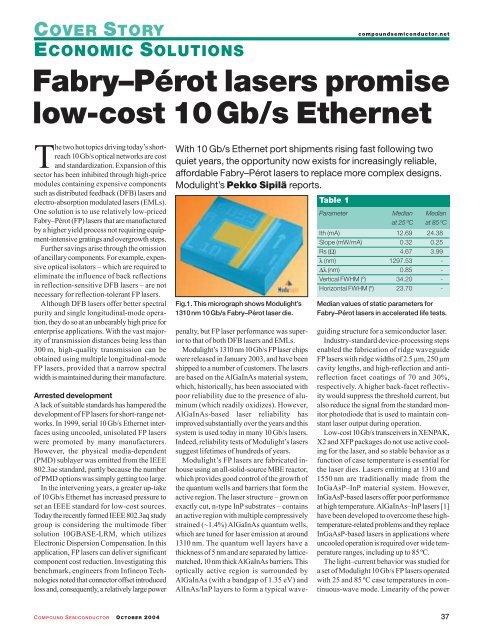
Fig.1. This micrograph shows <strong>Modulight</strong>’s<br />
13<strong>10</strong> nm <strong>10</strong> <strong>Gb</strong>/s Fabry–Pérot laser die.<br />
Table 1<br />
Parameter Median Median<br />
at 25 ºC at 85 ºC<br />
Ith (mA) 12.69 24.38<br />
Slope (mW/mA) 0.32 0.25<br />
Rs (Ω) 4.67 3.99<br />
λ (nm) 1297.53 -<br />
∆λ (nm) 0.85 -<br />
Vertical FWHM (º) 34.20 -<br />
Horizontal FWHM (º) 23.70 -<br />
Median values of static parameters for<br />
Fabry–Pérot <strong>lasers</strong> in accelerated life tests.<br />
penalty, but FP laser performance was superior<br />
to that of both DFB <strong>lasers</strong> and EMLs.<br />
<strong>Modulight</strong>’s 13<strong>10</strong> nm <strong>10</strong> <strong>Gb</strong>/s FPlaser chips<br />
were released in January 2003, and have been<br />
shipped to a number of customers. The <strong>lasers</strong><br />
are based on the AlGaInAs material system,<br />
which, historically, has been associated with<br />
poor reliability due to the presence of aluminum<br />
(which readily oxidizes). However,<br />
AlGaInAs-based laser reliability has<br />
improved substantially over the years and this<br />
system is used today in many <strong>10</strong> <strong>Gb</strong>/s <strong>lasers</strong>.<br />
Indeed, reliability tests of <strong>Modulight</strong>’s <strong>lasers</strong><br />
suggest lifetimes of hundreds of years.<br />
<strong>Modulight</strong>’s FP <strong>lasers</strong> are fabricated inhouse<br />
using an all-solid-source MBE reactor,<br />
which provides good control of the growth of<br />
the quantum wells and barriers that form the<br />
active region. The laser structure – grown on<br />
exactly cut, n-type InP substrates – contains<br />
an active region with multiple compressively<br />
strained (~1.4%) AlGaInAs quantum wells,<br />
which are tuned for laser emission at around<br />
13<strong>10</strong> nm. The quantum well layers have a<br />
thickness of 5 nm and are separated by latticematched,<br />
<strong>10</strong> nm thick AlGaInAs barriers. This<br />
optically active region is surrounded by<br />
AlGaInAs (with a bandgap of 1.35 eV) and<br />
AlInAs/InP layers to form a typical waveguiding<br />
structure for a semiconductor laser.<br />
Industry-standard device-processing steps<br />
enabled the fabrication of ridge waveguide<br />
FP<strong>lasers</strong> with ridge widths of 2.5 µm, 250 µm<br />
cavity lengths, and high-reflection and antireflection<br />
facet coatings of 70 and 30%,<br />
respectively. A higher back-facet reflectivity<br />
would suppress the threshold current, but<br />
also reduce the signal from the standard monitor<br />
photodiode that is used to maintain constant<br />
laser output during operation.<br />
Low-<strong>cost</strong> <strong>10</strong><strong>Gb</strong>/s transceivers in XENPAK,<br />
X2 and XFP packages do not use active cooling<br />
for the laser, and so stable behavior as a<br />
function of case temperature is essential for<br />
the laser dies. Lasers emitting at 13<strong>10</strong> and<br />
1550 nm are traditionally made from the<br />
InGaAsP–InP material system. However,<br />
InGaAsP-based <strong>lasers</strong> offer poor performance<br />
at high temperature. AlGaInAs–InP<strong>lasers</strong> [1]<br />
have been developed to overcome these hightemperature-related<br />
problems and they replace<br />
InGaAsP-based <strong>lasers</strong> in applications where<br />
uncooled operation is required over wide temperature<br />
ranges, including up to 85 ºC.<br />
The light–current behavior was studied for<br />
a set of <strong>Modulight</strong> <strong>10</strong> <strong>Gb</strong>/s FP <strong>lasers</strong> operated<br />
with 25 and 85 ºC case temperatures in continuous-wave<br />
mode. Linearity of the power<br />
COMPOUND SEMICONDUCTOR OCTOBER 2004 37
compoundsemiconductor.net<br />
output is very good even at 85 ºC – at this temperature<br />
InGaAsP-based <strong>lasers</strong> already show<br />
a significant power drop due to saturation of<br />
the slope efficiency. For our <strong>lasers</strong>, slope efficiency<br />
as a function of temperature is fairly<br />
constant. The median threshold current for the<br />
device is 12.97 and 25.41 mAat case temperatures<br />
of 25 and 85 ºC, respectively.<br />
Control is key<br />
An important factor that limits transmission<br />
distance is chromatic dispersion. Early suggestions<br />
for FPlaser-based <strong>10</strong> <strong>Gb</strong>/s PMDs for<br />
2 km transmission assumed a maximum rootmean-square<br />
(RMS) spectral width of<br />
2–2.5 nm. This requires a high degree of control<br />
throughout the entire manufacturing<br />
process, from wafer growth to test and measurement.<br />
The spectral properties of <strong>Modulight</strong>’s<br />
<strong>lasers</strong> are measured with an optical<br />
spectrum analyzer, and spectral RMS values<br />
are calculated assuming a noise level of<br />
–20 dB. Figure 2 shows the distribution of the<br />
RMS spectral width for a population of<br />
<strong>Modulight</strong>’s <strong>10</strong> <strong>Gb</strong>/s FP <strong>lasers</strong> operating at<br />
5mWat two case temperatures. Atypical value<br />
for the spectral width is 0.9 nm for a 25 ºC case<br />
temperature; the spectral width remains well<br />
be<strong>low</strong> 2 nm even at a 85 ºC case temperature.<br />
The frequency response of the laser chips<br />
was measured using a microwave probe and<br />
a network analyzer. The resonance frequency,<br />
which determines the maximum modulation<br />
speed of the device, was 13 GHz at 25 ºC and<br />
11.6 GHz at 85 ºC with a bias level of<br />
Ith + 66 mA. The change in resonance frequency<br />
over 60 ºC is only 11%, which is small<br />
compared with traditional InGaAsP<strong>lasers</strong> and<br />
AlGaInAs <strong>lasers</strong> [2].<br />
The long-term reliability of <strong>Modulight</strong>’s<br />
<strong>10</strong> <strong>Gb</strong>/s, 13<strong>10</strong> nm FP <strong>lasers</strong> has been studied<br />
by extended accelerated ageing tests in accordance<br />
with Telcordia guidelines. The study<br />
involves characterizing bare die laser chips at<br />
25 and 85 ºC prior to bonding on submounts.<br />
Before starting the time-consuming ageing<br />
test, devices were screened from standard production<br />
lots using a 24 hour burn-in test, conducted<br />
at 80 mAconstant current and <strong>10</strong>0 ºC.<br />
A burn-in induced change of more than –5<br />
or 1% in threshold current, or –2 or 5% change<br />
in slope efficiency in output power versus current<br />
measurements at 25 ºC led to rejection.<br />
Eleven devices meeting these criteria<br />
underwent an accelerated lifetime test, with<br />
conditions of <strong>10</strong> mW constant output power<br />
at 85 ºC. Chip-level static parameters for<br />
these <strong>lasers</strong> are summarized in table 1. These<br />
number of devices, N<br />
1200<br />
N (25°C) = 5929<br />
<strong>10</strong>0<br />
N (85°C) = <strong>10</strong>93<br />
90<br />
<strong>10</strong>00<br />
800<br />
80<br />
70<br />
60<br />
600<br />
50<br />
40<br />
frequency (25ºC)<br />
400<br />
frequency (85ºC)<br />
30<br />
cumulative (25ºC)<br />
cumulative (85ºC)<br />
20<br />
200<br />
<strong>10</strong><br />
0 0<br />
0 0.4 0.8 1.2 1.6 2.0<br />
RMS spectral width (nm)<br />
Fig. 2. More than 90% of <strong>Modulight</strong>’s <strong>lasers</strong><br />
have an RMS spectral width of less than<br />
1.3 nm at 85 ºC, which is well inside the<br />
2–2.5 nm required for 2 km transmission.<br />
<strong>10</strong> 8<br />
<strong>10</strong> 7<br />
<strong>10</strong> 6<br />
<strong>10</strong> 5 2 5 <strong>10</strong> 20 30 40 50 60 70 80 90 95 98<br />
cumulative failures (%)<br />
2<br />
time (h)<br />
Fig. 3. The median lifetime of a <strong>Modulight</strong><br />
laser is calculated to be 9 × <strong>10</strong> 5 hours.<br />
log <strong>10</strong><br />
FITs<br />
1<br />
0<br />
1<br />
11<br />
4<br />
8<br />
29<br />
12 16 20 24<br />
time (years)<br />
cumulative (%)<br />
28 32 36 40<br />
Fig. 4. These FIT values show that the <strong>lasers</strong><br />
are reliable enough for telecom applications.<br />
figures are typical of the several thousands of<br />
<strong>lasers</strong> fabricated by <strong>Modulight</strong> using the same<br />
process. More than 130,000 device hours<br />
have been collected and analyzed to evaluate<br />
laser reliability.<br />
For the laser analysis we defined end-oflife<br />
(EOL) as the time taken for the threshold<br />
current to increase by 50% from its initial<br />
value. The time to failure for each device can<br />
then be calculated by assuming that the EOL<br />
can be extrapolated linearly as a function of<br />
time. Calculations were performed on <strong>10</strong><br />
60<br />
COVER STORY<br />
ECONOMIC SOLUTIONS<br />
<strong>lasers</strong> – the remaining laser showed no clear<br />
degradation trend during the lifetime test, indicating<br />
an infinite lifetime.<br />
The analysis also assumed that only one<br />
wear-out failure mode exists and that laser lifetime<br />
fol<strong>low</strong>s a lognormal distribution. The<br />
lifetime data of the <strong>lasers</strong> at 85 ºC, alongside<br />
the line of best fit, is presented in figure 3. The<br />
median lifetime – the point where the fitted<br />
line intercepts the 50% point – is equal to<br />
9.38 × <strong>10</strong> 5 hours (<strong>10</strong>7 years). The median lifetime<br />
at other temperatures can be calculated<br />
if the activation energy – the energy associated<br />
with a particular failure mode – is known.<br />
Using Telcordia default activation energies<br />
of 0.4 eV for wear-out failure and 0.35 eV for<br />
random failures, at 25 and 40 ºC median lifetimes<br />
are 1.27 × <strong>10</strong> 7 hours (1450 years) and<br />
6.04 × <strong>10</strong> 6 hours (689 years), respectively.<br />
Lasers with longevity<br />
To the best of our knowledge, only a few<br />
reports exist regarding the reliability of<br />
AlGaInAs-based transmitter <strong>lasers</strong> operating<br />
at 13<strong>10</strong> nm [1, 3]. In reference 1, mean-timeto-failure,<br />
or median life, is estimated at<br />
82000 hours (9.4 years) at 85 ºC, which is significantly<br />
less than that predicted for our<br />
<strong>lasers</strong>. Work carried out by Takaguchi et al.<br />
[3] only indicates that no failures have been<br />
observed after 3400 hours of operation.<br />
Wear-out failure rates at 40ºC after 5, <strong>10</strong> and<br />
20 years of service can be calculated using the<br />
same lognormal model. A FIT value of 11 –<br />
that is 11 failures per billion device hours – is<br />
calculated for <strong>lasers</strong> with 5 years of service<br />
(see figure 4). Corresponding FIT values after<br />
<strong>10</strong> and 20 years are 29 and 60, respectively.<br />
These FIT numbers show that the <strong>lasers</strong> have<br />
sufficient long-term reliability for use in telecom<br />
equipment, where the industry-standard<br />
requirement is a FIT value of less than 200 for<br />
20years’design life. The reliability, allied with<br />
the attractive price of FP <strong>lasers</strong>, makes these<br />
devices competitive in short-haul <strong>10</strong><strong>Gb</strong>/s communications,<br />
particularly if standardization<br />
work proceeds successfully.<br />
●<br />
Further reading<br />
[1] C-E Zah et al. 1994 IEEE J. Quantum<br />
Electron. 30 511–523.<br />
[2] T Ishikawa et al. 1998 IEEE Photonics<br />
Technology Letters <strong>10</strong> 1703–1705.<br />
[3] T Takaguchi et al. 2000 ECOC Proceedings<br />
26 1.<br />
Pekko Sipilä is product line manager for<br />
transmitter laser products at <strong>Modulight</strong>.<br />
COMPOUND SEMICONDUCTOR OCTOBER 2004<br />
39