P.7 - Reactors for filtering - Circutor
P.7 - Reactors for filtering - Circutor
P.7 - Reactors for filtering - Circutor

Create successful ePaper yourself
Turn your PDF publications into a flip-book with our unique Google optimized e-Paper software.
<strong>Reactors</strong> <strong>for</strong> <strong>filtering</strong><br />
Switching micro-drop <strong>filtering</strong><br />
in the network and motor<br />
Point PCC<br />
Inverter<br />
Other loads<br />
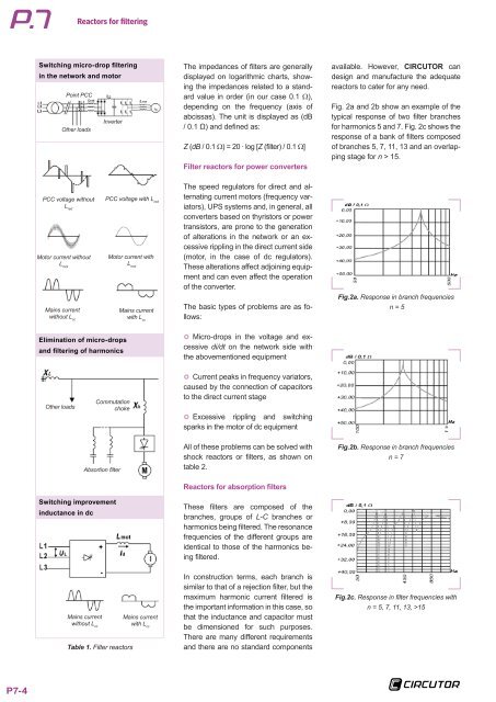
The impedances of filters are generally<br />
displayed on logarithmic charts, showing<br />
the impedances related to a standard<br />
value in order (in our case 0.1 Ω),<br />
depending on the frequency (axis of<br />
abcissas). The unit is displayed as (dB<br />
/ 0.1 Ω) and defined as:<br />
Z (dB / 0.1 Ω) = 20 · log [Z (filter) / 0.1 Ω]<br />
Filter reactors <strong>for</strong> power converters<br />
available. However, CIRCUTOR can<br />
design and manufacture the adequate<br />
reactors to cater <strong>for</strong> any need.<br />
Fig. 2a and 2b show an example of the<br />
typical response of two filter branches<br />
<strong>for</strong> harmonics 5 and 7. Fig. 2c shows the<br />
response of a bank of filters composed<br />
of branches 5, 7, 11, 13 and an overlapping<br />
stage <strong>for</strong> n > 15.<br />
PCC voltage without<br />
L red<br />
Motor current without<br />
L mot<br />
PCC voltage with L red<br />
Motor current with<br />
L mot<br />
The speed regulators <strong>for</strong> direct and alternating<br />
current motors (frequency variators),<br />
UPS systems and, in general, all<br />
converters based on thyristors or power<br />
transistors, are prone to the generation<br />
of alterations in the network or an excessive<br />
rippling in the direct current side<br />
(motor, in the case of dc regulators).<br />
These alterations affect adjoining equipment<br />
and can even affect the operation<br />
of the converter.<br />
Mains current<br />
without L cc<br />
Mains current<br />
with L cc<br />
The basic types of problems are as follows:<br />
Fig.2a. Response in branch frequencies<br />
n = 5<br />
Elimination of micro-drops<br />
and <strong>filtering</strong> of harmonics<br />
}}<br />
Micro-drops in the voltage and excessive<br />
di/dt on the network side with<br />
the abovementioned equipment<br />
Other loads<br />
Commutation<br />
choke<br />
}}<br />
Current peaks in frequency variators,<br />
caused by the connection of capacitors<br />
to the direct current stage<br />
}}<br />
Excessive rippling and switching<br />
sparks in the motor of dc equipment<br />
Absortion filter<br />
Switching improvement<br />
inductance in dc<br />
All of these problems can be solved with<br />
shock reactors or filters, as shown on<br />
table 2.<br />
<strong>Reactors</strong> <strong>for</strong> absorption filters<br />
These filters are composed of the<br />
branches, groups of L-C branches or<br />
harmonics being filtered. The resonance<br />
frequencies of the different groups are<br />
identical to those of the harmonics being<br />
filtered.<br />
Fig.2b. Response in branch frequencies<br />
n = 7<br />
Mains current<br />
without L cc<br />
Table 1. Filter reactors<br />
Mains current<br />
with L cc<br />
In construction terms, each branch is<br />
similar to that of a rejection filter, but the<br />
maximum harmonic current filtered is<br />
the important in<strong>for</strong>mation in this case, so<br />
that the inductance and capacitor must<br />
be dimensioned <strong>for</strong> such purposes.<br />
There are many different requirements<br />
and there are no standard components<br />
Fig.2c. Response in filter frequencies with<br />
n = 5, 7, 11, 13, >15<br />
P7-4