INTRODUCTION TO HELMET-MOUNTED DISPLAYS
INTRODUCTION TO HELMET-MOUNTED DISPLAYS
INTRODUCTION TO HELMET-MOUNTED DISPLAYS

You also want an ePaper? Increase the reach of your titles
YUMPU automatically turns print PDFs into web optimized ePapers that Google loves.
3<br />
<strong>INTRODUCTION</strong> <strong>TO</strong> <strong>HELMET</strong>-<strong>MOUNTED</strong> <strong>DISPLAYS</strong><br />
Michael M. Bayer<br />
Clarence E. Rash<br />
James H. Brindle<br />
In order to fully understand the sensory, perceptual, and cognitive issues associated with helmet-/head-mounted<br />
displays (HMDs), it is essential to possess an understanding of exactly what constitutes an HMD, the various<br />
design types, their advantages and limitations, and their applications. It also is useful to explore the developmental<br />
history of these systems. Such an exploration can reveal the major engineering, human factors, and ergonomic<br />
issues encountered in the development cycle. These identified issues usually are indicators of where the most<br />
attention needs to be placed when evaluating the usefulness of such systems.<br />
New HMD systems are implemented because they are intended to provide some specific capability or<br />
performance enhancement. However, these improvements always come at a cost. In reality, the introduction of<br />
technology is a tradeoff endeavor. It is necessary to identify and assess the tradeoffs that impact overall system<br />
and user sensory systems performance. HMD developers have often and incorrectly assumed that the human<br />
visual and auditory systems are fully capable of accepting the added sensory and cognitive demands of an HMD<br />
system without incurring performance degradation or introducing perceptual illusions. Situation awareness (SA),<br />
essential in preventing actions or inactions that lead to catastrophic outcomes, may be degraded if the HMD<br />
interferes with normal perceptual processes, resulting in misinterpretations or misperceptions (illusions).<br />
As HMD applications increase, it is important to maintain an awareness of both current and future programs.<br />
Unfortunately, in these developmental programs, one factor still is often minimized. This factor is how the user<br />
accepts and eventually uses the HMD. In the demanding rigors of warfare, the user rapidly decides whether using<br />
a new HMD, intended to provide tactical and other information, outweighs the impact the HMD has on survival<br />
and immediate mission success. If the system requires an unacceptable compromise in any aspect of mission<br />
completion deemed critical to the Warfighter, the HMD will not be used. Technology in which the Warfighter<br />
does have confidence or determines to be a liability will go unused.<br />
Defining the Helmet-Mounted Display<br />
Melzer and Moffitt (1997) describe an HMD as minimally consisting of "an image source and collimating optics<br />
in a head mount." From the perspective of U.S. Army rotary-wing aviation, Rash (2000) extended this description<br />
to include a coupling system that uses head and/or eye position and motion to slave one or more aircraft systems,<br />
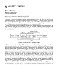
typically a head-directed sensor. Using this description, Figure 3-1 presents a basic block diagram in which there<br />
are four major elements: image source (and associated drive electronics), display optics, helmet, and head/eye<br />
tracker. The image source is a display device upon which sensor imagery is reproduced. Early on, these sources<br />
were miniature cathode-ray-tubes (CRTs) or image intensification (I 2 ) tubes. More recently, miniature flat panel<br />
display technologies have provided alternate choices. The display optics is used to couple the display imagery to<br />
the eye. The optics unit generally magnifies and focuses the display image. The helmet, while providing the<br />
protection for which it was designed originally, also now serves as a platform for mounting the image source and<br />
display optics. The tracking system couples the head orientation or line-of-sight with that of the pilotage sensor(s)<br />
and weapons.
48<br />
Figure 3-1. Block diagram of a basic U.S. Army rotary-wing aviation HMD.<br />
Chapter 3<br />
However, this extended description of HMDs is still limited by its close association with use in military rotarywing<br />
aircraft as well as being focused only on the visual system. Manning and Rash (2007) provide a more<br />
generalized description of visual HMDs that is applicable to both military and commercial applications, where the<br />
name “head-worn displays” (HWDs) has been gaining acceptance. The same basic four building blocks are<br />
employed but are expanded in scope:<br />
• A mounting platform, which can be as simple as a headband or as sophisticated as a full flight<br />
helmet. In addition to serving as an attachment point, it must provide the stability to maintain the<br />
critical alignment between the user’s eyes and the HWD viewing optics;<br />
• An image source for generating the information imagery that is optically presented to the user’s<br />
eyes. Advances in miniature displays have produced a wide selection of small, lightweight and lowpower<br />
choices at moderate cost, while meeting the demands of perceptual intensity and resolution<br />
(See Chapter 4, Visual Helmet-Mounted Displays.);<br />
• Relay optics, which transfer to the eye(s) the information at the image source. Relay optics typically<br />
consists of a sequence of optical elements (mostly lenses) that terminates with a beam-splitter<br />
(combiner). Initial designs for visual applications were monocular with a single beam-splitter in front<br />
of one eye, but as miniature display technologies develop, binocular designs are becoming<br />
dominant; 1 and,<br />
• A head-tracker, which is optional if the HWD is used only to present status information using nonspatially-referenced<br />
symbols. However, it often is required if external (outside) imagery is supplied<br />
by a sensor or a synthetic database. If such imagery is to be presented, the user’s directional line-ofsight<br />
must be recalculated continuously (updated) and used to point the sensor or to select the<br />
synthetic imagery data correlated with the user’s line-of-sight. Presentation of head-referenced<br />
information (imagery and/or symbology) via a head tracker requires a preflight calibration procedure<br />
called boresighting, which aligns the sensor’s and user’s lines-of-sight.<br />
Each of these fundamental HMD building blocks has engineering, sensory, perceptual, cognitive, and<br />
ergonomic considerations that will be explored in future chapters. All of these engineering and human factor<br />
1 For the audio realm, three-dimensional (virtual) audio technologies are being developed. Tactilely, small vibrators are<br />
being explored for 360 degree enhanced awareness.
Introduction to Helmet-Mounted Displays<br />
considerations are interrelated; therefore, tradeoffs are required in order to achieve a design that will be<br />
functionally acceptable for a specific operational application. As the tradeoffs are implemented, it is essential that<br />
the developer and the user be aware of the performance implications of these tradeoffs. The following sections<br />
will use the visually based HMD as an example of these considerations.<br />
Classifying Visual Helmet-Mounted Display Designs<br />
Since visual HMDs are complicated systems, there are several classification schemes that can be employed. These<br />
include those based on image source, image display technology, imagery presentation mode, and optical design<br />
approach. The image formed by an optic system, e.g., an HMD, can be real or virtual. At a practical level, the<br />
image is real if the light rays to be focused by the eye or a camera are spreading farther apart, i.e., diverging. This<br />
is the case when we view a real object directly or in a flat mirror, a photograph, the screen at a movie theater, or<br />
view an image focused by a convex lens from beyond its focal plane. The image formed is outside the optical<br />
system; the light rays (or wave front) from the image points that reach the eye are diverging. An image is virtual if<br />
the light rays to be focused by the eye are moving closer together, i.e., converging. Examples of virtual images<br />
include those from telescopes or microscopes focused by the user, a real scene viewed through a concave lens, or<br />
looking into a convex lens from a point inside its focal plane.<br />
Real-image HMD designs are rare. A direct-view image source like a miniature liquid crystal display (LCD)<br />
would have to be located no closer than reading distance, which is not practical. Putting the appropriate optics in<br />
front of the miniature display to move it closer to the eye would likely make the image virtual. All currently<br />
fielded HMDs are set to produce virtual images (although a slightly diverging system than produces some<br />
accommodation in the eye for presented symbology while viewing a real scene through the display may have<br />
some attentional advantages).<br />
Virtual image displays offer several advantages (Seeman et al., 1992). At near optical infinity, virtual images<br />
theoretically allow the eye to relax (reducing visual fatigue) and provide easier accommodation for older users.<br />
By providing a virtual image, a greater number of individuals (but not all) can use the system without the use of<br />
corrective optics. A collimated image also reduces effects of vibration that produces retinal blur.<br />
Shontz and Trumm (1969) categorize HMDs based on the mode by which the imagery is presented to the eyes.<br />
They define three categories: One-eye, occluded; one-eye, see-through; and two-eye, see-through. In the one- eye,<br />
occluded type, imagery is presented to only one eye, to which the real world is blocked, with the remaining eye<br />
viewing only the real world. The one-eye, see-through type, while still providing imagery to one eye, allows both<br />
eyes to view the real world. (Note: The optics in front of the imagery eye will filter the real world to a lesser or<br />
greater degree.) The Integrated Helmet and Display Sighting System (IHADSS) 2 employed on the AH-64 Apache<br />
helicopter is an example of this type. In the two-eye, see-through type, imagery is presented to both eyes, while<br />
the real world also is viewed by both eyes. 3 The Thales TopOwl TM is an example of this type.<br />
Another classification scheme, which parallels the three types described above, uses the terms monocular,<br />
biocular, and binocular. These terms refer to the presentation mode of the symbology and/or sensor imagery by<br />
the HMD. For our usage, monocular means the HMD sensor imagery is viewed by a single eye; biocular means<br />
the HMD provides two visual images from a single sensor or multiple sensors, but each eye sees exactly the same<br />
image from the same perspective; binocular means the HMD provides two visual images, one for each eye, from<br />
two sensors displaced in space, thus providing perspective. (Note: A binocular HMD can use a single sensor, if<br />
the sensor is manipulated to provide two different perspectives of the object scene.) Both biocular and binocular<br />
HMDs will have two optical channels (one for each eye). Note that a two-eyed HMD presenting biocular imagery<br />
2 The IHADSS system now is owned and manufactured by Elbit EFW, Fort Worth, TX.<br />
3 Not included in this classification scheme is a “two-eye, occluded” category such as Night vision Goggles (NVGs)<br />
49
50<br />
Chapter 3<br />
from one sensor/database is still capable of presenting binocular symbology overlays as long as it has two<br />
independently controllable image sources<br />
Typically, binocular HMDs use optical designs that fully overlap the images in each eye. In such HMDs, the<br />
field-of-view (FOV) is limited to the FOV of the display optics. However, in order to achieve larger FOVs, recent<br />
HMD designs partially overlap the images from two optical channels. This results in a partially-overlapped FOV<br />
consisting of a central binocular or binocular region (simultaneously seen by both eyes) and two monocular<br />
flanking regions (each seen by one eye only) (Figure 3-2). Such overlapping schemes can be implemented by<br />
either divergent or convergent overlap designs. In a divergent design, the right eye sees the central overlap region<br />
and the right monocular region, and the left eye sees the central overlap region and the left monocular region<br />
(Figure 3-3a). In a convergent design, the right eye sees the central overlap region and the left monocular region,<br />
and the left eye sees the central overlap region and the right monocular region (Figure 3-3b).<br />
Figure 3-2. Partially overlapped FOV with a central binocular region and two monocular regions<br />
The IHADSS is an example of a monocular HMD; the Aviator’s Night Vision Imaging System (ANVIS) is an<br />
example of a 100% overlapped binocular HMD; and the Kaiser Electronics’ CRT-based Helmet Integrated<br />
Display Sight System (HIDSS) design is divergent and has an overlap of approximately 30% (based on a 17º<br />
overlap region within the 52º horizontal FOV).<br />
Classifying HMDs by optical design is even more complicated. The simpler and more predominant types use<br />
optical designs based on reflective and refractive lens elements that relay the HMD image source to the eye. A<br />
standard characteristic of these designs is the presence of a final partially-reflective element(s) positioned in front<br />
of the user’s eye(s) called “combiners” (Wood, 1992). These elements combine the see-through image of the real<br />
world with the reflected image of the HMD image source. Reflective/refractive optical designs will be discussed<br />
in detail in Chapter 4, Visual Helmet-Mounted Displays.<br />
Another HMD type is based on a visor projection design (e.g., Cameron and Steward, 1994). A simple diagram<br />
of this design approach is presented in Figure 3-4. The image source(s) is usually mounted around (top/side) the<br />
helmet, and the image is relayed optically so as to be projected onto the visor where it is reflected back into the<br />
user’s eye(s). The advantages of visor projection HMDs include lower weight, improved center-of-mass (CM),<br />
increased eye relief, and maximum unobstructed visual field. A possible deficiency is image degradation that can<br />
result in a high vibration environment. An optical problem that can show up with this design is the production of<br />
ghost images. Also, this design requires that the visor be able to be placed consistently at the same position.<br />
Recently, visor projection designs have been revisited (Chapter 4, Visual Helmet-Mounted Displays).
Introduction to Helmet-Mounted Displays<br />
Figure 3-3a. Visual interpretation of the divergent display mode.<br />
Figure 3-3b. Visual interpretation of the convergent display mode.<br />
51
52<br />
Figure 3-4. Visor projection HMD design approach.<br />
Chapter 3<br />
Another approach, which again allows for low weight and provides a compact design, is one using holographic<br />
optical elements (Vos and Brandt, 1990). A holographic combiner is used to merge the standard combiner<br />
function with the collimation function usually performed by an additional refractive optical element. This merging<br />
implies that the holographic combiner acquires optical power, hence the term power combiner (Wood, 1992). In<br />
some designs, the visor serves as the combiner, with a holographic coating on the visor substrate. Disadvantages<br />
of this approach include the problem of preventing humidity and temperature effects from degrading the<br />
holograms. Considerable progress has been made in mitigating these problems in the last few years.<br />
One of the most recent entries into HMD design approaches is the use of lasers that scan an image directly onto<br />
the retina of the user’s eye (Johnston and Willey, 1995). Figure 3-5 provides a diagram of the basic retinal<br />
scanning approach. This approach eliminates the need for a CRT or flat panel (FP) image source, offering the<br />
potential of improving both weight and CM. Other cited advantages of this system include diffraction (and<br />
aberration) limited resolution, small volume (for monochromatic), full color capability, and high brightness<br />
potential. Disadvantages, at least potentially, include scanning complexity, susceptibility to high vibration<br />
environments (as with helmet slippage in military environments), limited exit pupil size, and safety concerns.<br />
Figure 3-5. Basic diagram of retinal scanning display (adapted from Proctor, 1996).
Introduction to Helmet-Mounted Displays<br />
A recent optical design for HMDs developed by BAE Systems uses wave-guide technology. This system uses<br />
holographic optics embedded between two transparent plates to direct the image to the eye. The potential<br />
advantages to this system are simplicity, large eye relief, ability to use in conjunction with existing night vision<br />
goggles (NVGs), lower cost, reduced weight and ability to adapt to existing military helmets. Although most of<br />
the disadvantages are unknown at this time, safety related to the plate placed in front of the eye and the eventual<br />
FOV have not been fully addressed. This approach is used in BAE System’s Q-Sight TM HMD discussed in the<br />
Current and Future HMD Programs section of this chapter.<br />
Regardless of the actual optical approach used, a visual aviation HMD also must include an image source, a<br />
head/eye tracker (if sensor is remotely located), and a helmet platform. At one time, the traditional approach was<br />
to integrate the optics and image source into a subsystem which was then mounted onto an existing helmet<br />
(Melzer and Larkin, 1987). This after the fact add-on approach was used with ANVIS. As one might expect,<br />
attaching one subsystem to another subsystem may not produce the optimal design. Instead, an integrated<br />
approach in which all elements and components of the HMD are designed in concert generally will result in the<br />
best and most functional overall design. The IHADSS was the first HMD product of the integrated approach, i.e.,<br />
the helmet and the HMD optics were developed as a system, even though the optics is a removable component.<br />
Even when using an integrated approach, the desired application of an HMD will impact design, leading to a<br />
variety of configurations. There is no one-design-fits-all scenario. In fact, the various missions, and the conditions<br />
under which they must be performed, are so different, that a single HMD design, while optimal for one set of<br />
conditions, may be significantly deficient for other mission scenarios. A solution to this problem may be a<br />
modular approach (Bull, 1990), where the HMD system consists of a base mounting unit (e.g., helmet platform),<br />
and interchangeable modules that can be attached, each for a specific set of mission requirements. This modular<br />
approach can be effective as long as an integrated approach is used that does not compromise the basic<br />
requirements of any subsystem. For example, the helmet, while now being used as a platform to attach optics, still<br />
must serve its primary functions of providing impact, visual, and acoustical protection. The HIDSS HMD design<br />
for the now cancelled U.S. Army Comanche program was an example of the modular approach.<br />
The visually-coupled system (VCS) concept<br />
Head-position sensing or head tracker technologies provide the pilot’s/operator’s “caged eyeball” line-of-sight as<br />
a control input to the aircraft/vehicle and its on-board sensors and weapons. This class of head-mounted system<br />
has sometimes been called a helmet-mounted sight. HMD technologies provide virtual image display capability<br />
integral to the user’s helmet. When combined, they form a class of systems many times referred to across the<br />
military community as VCS, as illustrated in Figure 3-6. With closed loop VCS, the head tracker technology<br />
serves as the control path input to sensors, weapons, avionics, or the vehicle itself, while the HMD technology<br />
provides the display symbology/imagery feedback. It should be noted that even the most basic head tracker<br />
requires at least a simple display reference a “crosshair” or “reticle” so the user knows what line-of-sight is being<br />
sensed. It is also worth noting that the image intensification technology (commonly referred to as NVGs) that has<br />
evolved over this same timeframe represents a “self-contained” VCS, in that NVGs present spatially-referenced<br />
image intensification information to the wearer.<br />
VCS take advantage of the psycho-motor skills of the operator to provide an intuitive visual interface to the<br />
vehicle, its on-board systems, and the surrounding environment. VCS provide a “look-and-shoot” vs. a “point-thevehicle-and-shoot”<br />
capability for effective targeting of airborne and ground, and stationary and moving ground<br />
targets. This class of systems provides an expanded off-axis visual capability for the entire range of mission<br />
requirements. As time has gone on, there has been an increase in situations where the individual Warfighter is the<br />
“weapon platform” of choice with rapid adaptability and real-time decision-making before the enemy can react.<br />
Human systems, and in particular, visually-coupled display systems, optimize and sustain the human role in<br />
combat operations.<br />
53
54<br />
The History of Helmet-Mounted Displays<br />
Figure 3-6. Visually-coupled system concept block diagram.<br />
Chapter 3<br />
The official history of HMDs starts almost a century ago, with Albert Bacon Pratt, of Lyndon, Vermont. During<br />
the height of World War I, between 1915 and 1917, Pratt was awarded a series of U.S. and U.K. patents<br />
(Marshall, 1989), for an “Integrated Helmet Mounted Aiming and Weapon Delivery System” for a marksman<br />
(Figure 3-7).<br />
Figure 3-7. Albert Pratt’s helmet-mounted display (Marshall, 1989).<br />
Pratt, a chemical engineer, claimed a few features in his patent that have survived through the years and are as<br />
valid today as they were 100 years ago. A couple of comparisons between Pratt’s patent claims and features of<br />
today’s HMD designs will help establish his design as the precursor of current HMDs.
Introduction to Helmet-Mounted Displays<br />
• Size and Fit<br />
“The helmet preferably will be made in two sizes, a large size and a small size. To adapt the helmets to fit<br />
different size heads the lower section is provided with flexible linen.”<br />
Today’s flying helmets are designed in small, medium, large and extra large sizes; the liner is<br />
customized to individual pilots.<br />
• Target Acquisition<br />
“The gun is automatically aimed unconsciously to the turning of the head of the marksman in the<br />
direction of the target. In self-protection one instinctively turns the head in the direction of attack to see<br />
the enemy. Thus, the gun is automatically directed toward the target.”<br />
Today’s HMDs embody the same “look-and-shoot” philosophy; sophisticated technology with Kalman<br />
filtering tracks the instantaneous pilot’s line-of-sight to guide missiles to the target.<br />
• Dual Use<br />
On a lighter note, the crown of Pratt’s helmet (Item #7) doubled as a cooking pan, with the gun barrel<br />
safeguard (Item #213) serving as the handle. Whereas some might think the top spike (Item #8) is<br />
intended for hand-to-hand combat, it is simply stuck into the ground to support the pan while dining in<br />
the field.<br />
Also, despite conducting an in-depth literature research, the authors of this chapter were not able to<br />
identify a like-functionality for modern helmets. 4 Advantage, Pratt!<br />
The concept and the potential applications of HMDs in aircraft cockpits have fascinated military aviation<br />
strategists for decades. The idea of placing a virtual image focused at infinity in the visual path of the pilot and<br />
overlaying computer-generated images so that mission critical information is always available with “eyes-out,”<br />
has mobilized incredible technical and financial resources over the last decades. It is generally acknowledged that<br />
an HMD, when part of a Visually Coupled System (VCS), is among the most valuable visual aids in the arsenal of<br />
a military pilot. Experience has shown that nothing can be added to a tactical aircraft that give more “bang for the<br />
buck” or operational payoff-per-pound-added than a VCS.<br />
Military HMD development: historical overview<br />
The various militaries across the world have actively pursued the research, development, application, and fleet<br />
introduction of a variety of helmet-mounted technologies for over forty years. A complete overview of the HMD<br />
technology development over the last forty years would be difficult as there have been hundreds of head tracker<br />
and HMD development efforts. Additionally, in recent years the concept of virtual reality has spurred interest in<br />
HMDs within industry and the general population. One artifact of the vast interest in HMDs has been the failure<br />
of the military (and more recently the commercial) communities to develop and accept an overall plan that would<br />
establish unambiguous guidelines for HMD development, not that such efforts have not been attempted.<br />
Within the U.S., in 1995 (Brindle, Marano-Goyco, and Tihansky, 1995) under the auspices of a Tri-Service<br />
Working Group reporting to the Office of the Undersecretary of Defense for Research and Engineering, a<br />
technology-development taxonomy was established to help the HMD community properly categorize and<br />
4<br />
The modern plastics-composite helmet has lost considerable functionality, as the early steel-pot was used to cook, wash,<br />
dig, etc.<br />
55
56<br />
Chapter 3<br />
articulate the diverse spectrum of research and development (R&D) programs underway at any point in time. The<br />
taxonomy’s main categories included:<br />
• Human System Integration, dealing mostly with efforts on safety, anthropometry, vision, situation<br />
awareness, spatial disorientation, symbology, and audio performance/hearing protection.<br />
• Component Development, focusing on optics, image intensification, head trackers, image sources,<br />
three-dimensional (3-D) audio, and voice recognition; interconnect technology/ systems, and symbol<br />
generation/graphics.<br />
• System Development for air and ground vehicles, the individual warrior, and simulation.<br />
• System Integration and Analysis, coordinating all R&D efforts dealing with a) helmet system<br />
integration – both the integration of the various VCS components with each other and with existing<br />
personal life support equipment; and b) vehicle/laboratory system integration for properly integrating<br />
the helmet-mounted system with the vehicle and the vehicle sensors/weapons/subsystems.<br />
• Application Demonstration/Measurement and Evaluation, oriented toward laboratory measurements,<br />
simulation evaluations, flight-worthiness testing, flight evaluations, concept demonstrations and field<br />
trials.<br />
In order to highlight and summarize the wide range of HMD developments over the past decades, it may be<br />
useful to briefly describe those efforts that have progressed all the way from initial R&D, through prototyping and<br />
production, and into fielding (even if limited). Some of these programs will be summarized in greater detail in the<br />
Current and Future HMD Programs section of this chapter.<br />
One of the earliest (1970s) sighting HMD systems to be fielded was the electro-mechanical linkage headtracked<br />
sight used to direct the fire of the gimbaled gun in the U.S. Army’s AH-1G Huey Cobra attack helicopter<br />
(Braybrook,1998). The pilot aimed the gun by superimposing a helmet-mounted reticle over the target.<br />
Not too long after the Cobra head tracker system (1973-1979), the Navy introduced an electro-optical headtracking<br />
system into its later Phantom models F-4J and F-4N fixed-wing jet aircraft, coupled with the radar and<br />
AIM-9H Sidewinder missiles (Klass, 1972). The Visual Target Acquisition System (VTAS), shown in Figure 3-8,<br />
consisted of photo diodes on either side of a “halo assembly” that mounted on the standard fixed-wing flight<br />
helmet. Sensor surveying units on either side of the cockpit scanned the helmet in the “head motion box.” The<br />
pilot used a visor-projected reticle and cueing discretes to interface with the fire-control radar and missiles for<br />
daytime, off-boresight, air-to-air targeting.<br />
As was the case with the Cobra application, these head trackers yielded a significant reduction in the time<br />
required to bring weapons to bear on target. VTAS was discontinued in the 1970’s (Dornheim, 1995) due to its<br />
technological limitations.<br />
The first complete VCS system to see operational use was the introduction in the early 1980s of the IHADSS<br />
by the U.S. Army in the AH-64 Apache attack helicopter (Figure 3-9). The head tracking technology in the<br />
IHADSS was the electro-optical technology similar to the Navy VTAS. However, the HMD technology was<br />
much more capable and provided higher resolution dynamic video imagery by using a miniature 1-inch CRT with<br />
relay optics.<br />
The monocular IHADSS serves as the crew interface for both the pilot and copilot/gunner. The pilot’s IHADSS<br />
is interfaced with a 30° x 40°-FOV thermal sensor (mounted on the nose of the aircraft) to form a head coupled,<br />
one-to-one magnification pilotage system. The copilot’s IHADSS is interfaced with a switchable-FOV thermal<br />
targeting sensor to form an effective off-boresight interface with the head-slaved gun and missiles. In both cases,<br />
the appropriate flight-control or fire-control symbology is mixed electronically with the thermal imagery. The<br />
systems have been used effectively for both day and night missions for almost three decades (Rash, 2008).<br />
Recently, in the fixed-wing community, the U.S. Air Force and U.S. Navy have introduced the Joint Helmet-<br />
Mounted Cueing System (JHMCS) into the F-15, F-16 and F-18 aircraft. The JHMCS utilizes magnetic head
Introduction to Helmet-Mounted Displays<br />
tracker technology and provides a monocular, visor-projected display of stroke-written dynamic symbology from<br />
a ½-inch miniature CRT and relay optics (Figure 3-10). The JHMCS provides a daytime air-to-air and air-toground<br />
off-boresight targeting capability, especially valuable when used with high off-boresight missile seeker<br />
technology.<br />
Figure 3-8. Visual Target Acquisition<br />
system (VTAS) HMD.<br />
Figure 3-9. Integrated Helmet and<br />
Display Sight System (IHADSS).<br />
Figure 3-10. Joint Helmet-<br />
Mounted Cueing System<br />
(Vision Systems International).<br />
The U.S. military Services began working on a class of VCS called multi-mode HMDs in the mid 1980’s. A<br />
multi-mode HMD, in a single integrated system, functionally provides an image-intensified view of the wearer’s<br />
environment (similar to NVGs), as well as a day/night display of spatially-referenced imagery (e.g., low-light<br />
level TV, forward-looking infrared [FLIR]) and symbology like a traditional VCS. This is illustrated in the<br />
example shown in Figure 3-11. The U.S. Navy first implemented a developmental model based on IHADSS, and<br />
numerous R&D efforts including U.S. Army Comanche HIDSS program and U.S. Navy Advanced Helmet Vision<br />
System program, which pursued both discrete optics and visor-projected versions of this class of system. These<br />
types of head-coupled systems not only functionally perform the night NVG and day/night HMD mission, but<br />
they also provide “sensor fusion” capability by simultaneously presenting correlated, spatially-referenced<br />
information to the user in the visible and near/far infrared regions of the electromagnetic spectrum. Recent<br />
developmental multi-mode HMDs, e.g., the Comanche HMD and Advanced Helmet Vision System programs,<br />
current HMD efforts for the Joint Strike Fighter (JSF) for the U.S. Navy and U.S. Air Force, and the AH-1<br />
upgrades for the U.S. Marine Corps, are binocular/biocular, helmet-mounted vision systems.<br />
Outside the United States, the first “modern” helmet-mounted sight (HMS) was the optically-sensed Russian<br />
design, developed to support the Vympel R-73/AA-11 Archer high off-boresight seeker, air-to-air missile, carried<br />
by the MiG-29 Fulcrum and the Su-27 Flanker, and built to attach to the ZSh-5 series Russian helmet (Beal and<br />
Sweetman, 1997). Even though this HMS (Arsenal’s Zh-3YM-1) was relatively rudimentary, lacking missilecueing<br />
symbols and using only a flip-down monocle with a light-emitting-diode (LED) reticle for aiming, the<br />
combination of the HMS and R-73 missile provided the Soviets with a greatly improved close combat capability<br />
(Merryman, 1994). The Arsenal Design Bureau (Kiev, Ukraine) subsequently improved on this first HMS with<br />
newer versions, like the Sura and Taurus. The combination MiG-29/ AA-11 were sold to the air forces in India,<br />
Iraq, North Korea, Libya, Syria, Iran, Yugoslavia and potentially Cuba (Lucas, 1994).<br />
During the Cold War the Russians developed and deployed force-multiplier HMD and HMS systems that gave<br />
them an edge on air superiority and then sold these systems to (then) unfriendly nations. The combination of an<br />
57
58<br />
Chapter 3<br />
HMD-guided, 4 th generation (GEN-4) missile and even inferior aircraft reduced to zero the technology advantage<br />
enjoyed by U.S. fighter aircraft. This caused a surge in HMD development programs in the Western countries.<br />
The Israeli Display and Sight Helmet (DASH) 3/ Python 4 combination (1990s) had an equally important<br />
impact on HMD development. The Python-4 was a missile system that had limited "fire-and-forget" capability, as<br />
well as helmet-sight guidance. The DASH HMS system by Elbit Systems was developed for Israeli F-15s and F-<br />
16s and will be discussed in more detail in the Current and Future HMD Programs section later in this chapter, as<br />
it is considered to have played an important role in the development history of today’s HMD.<br />
Advantages of Helmet-Mounted Displays<br />
There is little argument that displays and their ability to provide information are a distinct advantage in any<br />
operational setting. It would be unthinkable to offer an automobile design that failed to provide the driver with<br />
displays that provide real-time presentations of such operational parameters as speed and fuel status. While such<br />
information is not critical to the second-to-second operation of the automobile, drivers depend on being able to<br />
“look down” at the display console and obtain this information as needed.<br />
However, there are operational settings where certain displayed information is critical on a second-to-second<br />
basis. For example, in fast-moving aircraft flying close to the ground, the operational environment changes so<br />
rapidly that even the brief time it takes a pilot to glance down at one or more displays to obtain aircraft flight<br />
status information may severely degrade his/her situation awareness. This short-coming of “head-down” displays<br />
gave rise to the development of head-up displays (HUDs) (Figure 3-12). HUDs employ fixed, transparent pieces<br />
of glass or plastic mounted inside the aircraft windscreen (e.g., combiners or beamsplitters). HUDs allow critical<br />
flight data to be accessed in a head-up, eyes-out scenario. This offers a tremendous advantage in applications<br />
where the time taken to view head-down displays can negatively impact safety and performance. The use of<br />
HUDs is not limited to aircraft. They have been employed in racecars, another application where outside<br />
operational conditions change so rapidly that a constant eyes-out requirement exists (Qt Auto News, 2006).<br />
HUDs also are finding applications in less demanding vehicles. In an attempt to reduce accidents by preventing<br />
extended attention to head-down radio and CD-player knobs and buttons, a number of car manufacturers offer a<br />
windshield HUD. General Motors offers a HUD option on its Cadillac XLR/SRS models. The HUD presents a<br />
speedometer, turn signal indicators, audio system data, gear indication and cruise control settings (Dupont Corp,<br />
2004).<br />
But, as advantageous as HUDs are, they are fixed forward and are not as useful when the user is required to<br />
exercise constant head movement, e.g., constantly searching for enemy aircraft in a 360° environment. This factor<br />
played an important role in the motivation to mount the display on the head (or other head-mounted platform such<br />
as a helmet).<br />
The potential benefits of HMDs have captivated the aircraft community for 40 years. The HMD concept can be<br />
extended and transferred to other areas where a wide field-of-regard is beneficial. While early HMD development<br />
was aviation driven, their utility beyond aviation has not been overlooked. Tank commanders can benefit by<br />
staying in touch with the “outside world” while remaining protected. Dismounted soldiers (classic infantry) can<br />
maintain constant situation awareness of the digital battlefield as well as expanded and enhanced sensory inputs<br />
via HMDs.<br />
Nevertheless, the basic virtue of HMDs is to provide the ability to “look and shoot” at a target as fast as<br />
possible after target identification is completed. A dog fight usually lasts 30 to 60 seconds – the few seconds<br />
saved by eliminating aircraft pointing gives the pilot a vital advantage. Using the HMD, the pilot can quickly<br />
“tag” the enemy aircraft, launch a missile, and then turn to the next target and repeat the procedure. Sequential<br />
targeting enables a pilot to deal with multiple threats simultaneously, by eliminating the limitation posed by<br />
aircraft maneuverability.
Introduction to Helmet-Mounted Displays<br />
Figure 3-11. Example of multi-mode imagery with dynamic symbology.<br />
Figure 3-12. Example of head-up display (HUD) in F/A-18C (National Aeronautics and Space<br />
Administration).<br />
The dramatic threat coverage improvement provided by the wide field-of-regard of HMDs is shown in Figure<br />
3-13. Comparisons are shown for a HUD, typical forward-looking radar, and off-boresight missile system.<br />
The process of actively “tagging” targets is not limited to the individual platform: the pilot can identify a target<br />
and pass the information to an air surveillance and control platform (e.g., the Airborne Warning and Control<br />
System [AWACS] and Joint Surveillance Target Attack Radar System [JSTARS]), to other own sensors, or to<br />
another aircraft. Similarly, the opposite is useful as well - a detected threat by another platform or aircraft can be<br />
used to add cueing information to the HMD (Chapman and Clarkson, 1992).<br />
59
60<br />
Figure 3-13. Depiction of expanded HMD/ HMS threat coverage.<br />
Chapter 3<br />
For this reason, HMDs have increasingly been replacing and augmenting standard console-mounted head-down<br />
and traditional HUDs in advanced crew station designs. HMDs offer potentially greater direct access to critical<br />
visual information, while offering greater flexibility of head movement, less total system (but not user headborne)<br />
weight, and greater flexibility in use of vehicular interior space, although at the cost of greater system<br />
complexity and possible expertise degradation in the case of system malfunctions.<br />
More importantly, it is argued that HMDs provide users with increased situation awareness. Situation<br />
awareness encompasses the total information available, used to create an accurate picture of a battle theater,<br />
including spatial position and orientation of the aircraft, the surrounding areas, and any aircraft-relevant<br />
information. The pilot has to be aware of many different forms of information which is used to make judgments<br />
on how to respond to a given situation; any subtle level of perceptual cognizance to one's immediate environment<br />
can be vital for success in most situations (McCann and Foyle, 1995). The following operational definition of<br />
situation awareness has been proposed by a U.S. Air Force Staff Group: “A pilot’s (or aircrew’s) continuous<br />
perception of self and aircraft in relation to the dynamic of flights, threats, and mission, and the capability to<br />
forecast, then execute tasks based on the perception” (Geiselman, 1994).<br />
In general situation awareness can be classified into Global (the "far domain") and Tactical (the "near<br />
domain"), covering close combat and navigational areas (Lucas, 1994). Global situation awareness refers to the<br />
range between 50 and 200 miles from the aircraft and related information is available from the main display on<br />
the instrument panel; whereas, Tactical situation awareness is the close range area within 50 miles, with<br />
information in the forward visual path. Each of these has associated temporal drivers as well, with faster reactions<br />
required the closer the relevant stimulus. This makes it physically impossible to see both domains simultaneously.<br />
As a result, pilots adopt a sequential acquisition scanning strategy by transitioning back and forth from the headdown<br />
instrument display to outside viewing, sampling information from first one domain, then the other. This<br />
recurrently interrupts the process of information acquisition and requires time-consuming actions, such as eye and<br />
head movements, eye accommodation, and becoming reacquainted with the alternating domains. Furthermore, as<br />
long as the pilot is looking at one domain, a sudden event (or sudden state change) in the other domain may be<br />
undetected.<br />
By centralizing critical flight information within a user’s line-of-sight, overall performance is increased and<br />
operational safety is enhanced. HMDs offer users the advantage of monitoring critical information without having<br />
to repeatedly look down to scan instrument displays. Another proven benefit is that, with the ability to keep their<br />
eyes fixed to the outside world, users are more likely to detect important changes within the FOV (Harris and<br />
Muir, 2005: Manning and Rash, 2007). A specific example of the utility of this advantage is the greater
Introduction to Helmet-Mounted Displays<br />
probability in identifying runway incursions in military, civil and commercial aviation due to increased ability to<br />
maintain eyes out of the cockpit. Figure 3-14 depicts a typical HMD image. Note: This centralizing of critical<br />
flight information on front of the user’s eye(s) should not be confused with the placement of the information<br />
(symbols) themselves, as early development of HMDs showed that symbology is most effective when placed<br />
around the periphery of the HMD imagery.<br />
Figure 3-14. HMD Display (BAE Systems).<br />
Limitations and Disadvantages of Helmet-Mounted Displays<br />
Unfortunately, HMDs are not without their limitations and disadvantages. Some of the disadvantages are common<br />
to their predecessor, the HUD. First is the phenomenon of “attention capture” – or tunneling – which is the<br />
unwanted tendency for pilots to pay too much attention to the HUD and not enough attention to events in their<br />
field of vision outside the airplane (Foyle et al., 1993; McCann et al., 1993; McCann and Foyle, 1995). Attention<br />
capture with HUDs mounted just inside a windshield has been blamed for undetected runway incursions – one of<br />
the types of events that HUDs are to prevent. Numerous studies have attempted to understand attention capture<br />
and how it can be mitigated. Most disturbing is a developing consensus that HUDs (and hence HMDs) limit a<br />
pilot’s ability to simultaneously process information derived from HUDs and from the real world (McCann et al.,<br />
1993).<br />
Many HUD and HMD symbols are not “conformal” – that is, they are not overlaid in a one-to-one relationship<br />
to match shapes and features in the real world. Therefore, the symbols are perceived as different from the scene<br />
outside an aircraft’s windows. This causes pilots to deliberately shift their attention to view either the symbols or<br />
the outside scene. The transition to conformal symbology may mitigate the attention capture problem (Wickens<br />
and Long, 1994). This conformity must be required for video imagery presented in HMDs. In other words,<br />
information is generated and presented based on conventions that users have to learn (train) to recognize:<br />
cognition processes as intuitive as they may be, are always slower than the instincts.<br />
A second disadvantage is the possibility that HUD symbols or other imagery could obscure critical objects in<br />
the outside scene (Foyle et al., 1993). This problem can be reduced by keeping the number of symbols presented<br />
to a minimum and within the recommended size. Reducing the clutter caused by too many symbols also can<br />
decrease the potential for attention capture.<br />
61
62<br />
Chapter 3<br />
In addition to these general HUD-related disadvantages, other concerns are unique to HMD, as well as unique<br />
to the concept of mounting the display to the head. The first of these is user acceptability, which is important<br />
when any new technology is introduced; without user acceptance, the technology will not be used. The primary<br />
factors affecting acceptance are the head-supported weight, center-of-mass offset, required modification in head<br />
movement, display image quality/legibility, and display jitter and lag.<br />
Most non-military pilots are not accustomed to wearing more than a headset on their heads. Current civil and<br />
commercial aviation headsets are generally lightweight, typically 12 to 18 ounces (340 to 510 grams) (Rash,<br />
2006a). HMDs can increase head-supported weight by at least 16 ounces (454 grams). Military pilots wear<br />
helmet-based HMDs that weigh in excess of 4 pounds (lbs) (1.8 kilograms [kg]).<br />
Because the HMD’s display optics must be placed around the helmet with at least the combining element/visor<br />
in front of the eye, the HMD’s additional weight is likely to be above and forward of the human head’s natural<br />
center of mass - a factor that, as a flight progresses, may result in muscle fatigue.<br />
For HMDs to present sensor and synthetic imagery that represent what a user is seeing, the HMD must<br />
incorporate head-tracking. The need for head-tracking increases the cost and the complexity of HMDs.<br />
The head-tracking process of determining the user’s head position, relaying this position to the sensor, the<br />
sensor’s movement to the correct line-of-sight, the sensor’s acquisition of the scene, and transmitting and<br />
presenting the final imagery on the HMD takes time (Rash, 2000). This time is called system latency. Latency<br />
times are typically hundreds of milliseconds (ms). The largest contributor is the “slew rate” of the sensor, or the<br />
time for the sensor to move to the line-of-sight defined by the new head position. Studies have shown that total<br />
system-latency times approaching one-third of a second or longer (~300 ms) are unacceptable from a performance<br />
standpoint. Many in the VCS community today are trying to achieve a total system latency time of less than one<br />
display frame time (typically 33 ms).<br />
These latency times have been blamed for motion sickness. The onset and severity of motion sickness<br />
symptoms are difficult to predict, and such occurrences in commercial aviation would be unacceptable. Studies by<br />
the U.S. National Aeronautics and Space Administration (NASA) have documented the need for improvement in<br />
image alignment, accuracy and boresighting of HMDs to help mitigate this problem (Bailey et al., 2007).<br />
Helmet-Mounted Display Applications<br />
There is general agreement that HMDs have great potential applications; why, then, have only a few systems<br />
(mostly military) been fielded? Many factors contribute to this situation: cost, lagging technology, less than<br />
optimal ergonomics design (Keller and Colucci, 1998), unfinished search for that “application” that will excite<br />
users, unawareness of the potential benefits, and simply the “visceral dislike” (Hopper, 2000) of wearing a<br />
monitor on ones head. Four decades into the HMD exploration, the “killer application” that will propel the<br />
technology has not yet been identified.<br />
Ivan Sutherland (1965) proposed the “Ultimate Display”, more than 40 years ago (Figure 3-15). While at the<br />
Department of Computer Science, University of Utah, Sutherland imagined a display in which all-powerful<br />
computers would generate graphics of objects that would behave exactly (in all sensory modes) as their real-world<br />
counterparts. Implied in his concept were certain characteristics and expectations: a) the need for a complete<br />
sensory response: sight, sound, smell, feeling (haptic), and kinetic feedback to create the new reality and b) the<br />
use of HMDs will serve as a step toward an intuitive interface between human and machine, a natural way to add<br />
3-D to an otherwise flat computer imagery. This display is still far into the future, but the anticipated technologies<br />
have come to fruition as we have moved into the 21 st century. Others still are found only in science fiction.<br />
Nonetheless, Sutherland’s HMD concept opened the way to computer-generated 3-D stroke images coupled with<br />
head trackers – the same basic principles applied today.
Introduction to Helmet-Mounted Displays<br />
Figure 3-15. Ivan Sutherland's HMD (late 1960’s) (Department of Computer Science, University of Utah).<br />
The military has led in the applications of HMDs, and there is a growing interest in industrial and consumer<br />
applications. Some current and future potential applications are listed below. It must be noted that there are no<br />
rigid boundaries between these applications, as some applications have multiple usage across these boundaries.<br />
The use of HMDs in simulation and training has been adopted by both military and industrial users, and has<br />
served as a precursor to consumer gaming.<br />
Military applications include:<br />
• Navigation and situation awareness<br />
• Targeting<br />
• Night vision systems<br />
• Visual enhancement<br />
• Security monitoring<br />
• Simulation and training<br />
• Maintenance and inspection<br />
• Remotely-piloted vehicle interface<br />
Commercial applications include:<br />
• Computer-aided design/ Computer-aided engineering (CAD/CAE)<br />
• Surgical aid - microsurgery, endoscopic surgery<br />
• Emergency medical telepresence<br />
• Security monitoring<br />
• Maintenance, Repair and Overhaul (MRO)<br />
Consumer applications include:<br />
• Gaming<br />
• Mobile Internet access<br />
• Private DVD viewing<br />
• Fire-fighting<br />
63
64<br />
Chapter 3<br />
The following sections briefly describe and discuss some of the more important and interesting applications<br />
within the three areas: military, commercial and consumer.<br />
Military applications<br />
Military applications are the focus of this book – the merits of HMDs for both fixed- and rotary-wing aircraft are<br />
beyond questioning, and HMDs already have become an integral part of the next-generation cockpits. Much of<br />
this success is due to the use of head/helmet-tracking to produce visually-coupled HMD systems.<br />
Use of visually-coupled systems (VCS) for pilotage, navigation and/or situation awareness<br />
VCS technologies have been used for a tremendous variety of mission applications over the years. As previously<br />
noted for early applications of helmet-mounted sights, head-position sensing was used for a variety of line-ofsight<br />
designation and targeting in conjunction with onboard weapons and sensors. Some of the earliest<br />
investigations of HMD technologies were designed as a way to investigate a wider FOV display in cockpits or<br />
crew stations of various air, ground, and maritime vehicles.<br />
Over the years, the military has interfaced helmet-mounted sights and HMDs to a wide variety of vehicle<br />
systems and weapons. They have been linked with radars, electro-optical/TV missile systems, reconnaissance<br />
sensors, long-range target identification sensors, pilotage sensors, head-slaved guns (both air-to-ground and<br />
surface-to-air), and angle-rate bombing sensors. They have been interfaced with distributed aperture sensor<br />
systems for a total coverage “windowless cockpit” synthetic vision system capability for both aircraft and ground<br />
vehicles. They have been used to present spatially-referenced “highway-in-the-sky” type flight control<br />
information for both fixed-wing ejection seat aircraft and rotary-wing operations and for shipboard landings, and<br />
to present “predictor” fire control dynamic symbology such as “hotline gun sight.” These are fairly typical VCS<br />
applications.<br />
There have also been some “non-traditional” VCS applications attempted by the military over the years. One<br />
example is the use of a head tracker and HMD as an effective operator interface with a remotely piloted vehicle.<br />
By using VCS, the “illusion” can be created for the operator that they are “out there onboard the vehicle.” The<br />
military has successfully interfaced VCS with airborne, ground-based, and undersea unmanned vehicles for a<br />
wide variety of missions including reconnaissance, targeting, bomb disposal, undersea operations and other<br />
teleoperator applications.<br />
Virtual cockpit<br />
The “Virtual Cockpit” is a second application that has moved forward in the military with the main goal of<br />
providing a “software reconfigurable cockpit.” In the late 1990s the U.S. Army’s Program Manager-Aircrew<br />
Integrated Systems (PM-ACIS), Huntsville, Alabama, initiated the Virtual Cockpit Optimization Program<br />
(VCOP) to integrate advanced technologies into a single system. VCOP technologies included a Retinal Scanning<br />
Display (RSD); fully integrated 3-D cockpit audio technologies with speech recognition and synthesis; an<br />
Integrated Caution, Warning and Advisory Annunciator (ICWAA); and an Electronic Data Manager (EDM); all<br />
integrated and managed by the Rotorcraft Pilot’s Associate (RPA) Software. These technologies were intended to<br />
enhance situation and threat awareness, while at the same time providing a cost-effective technique to modernize<br />
legacy aircraft. In its simplest configuration, VCOP goals were to:<br />
• Provide efficient access to critical information with minimized “head-down” time;<br />
• Formulate “standardized” dashboard panel requirements; and
Introduction to Helmet-Mounted Displays<br />
• Establish an environment for rapid avionics prototyping, integration, test and evaluation of multiple<br />
aircraft configurations.<br />
A similar program was initiated in Japan, in the early 2000’s, by a team coordinated by Kawasaki Heavy<br />
Industry and Yokogawa Electric Corporation (Bayer, 2007). Similar to U.S. Army’s VCOP, this program’s goals<br />
were to:<br />
• Minimize cockpit cost and weight;<br />
• Develop reconfigurable configuration between manned- and unmanned combat aircraft; and<br />
• Increase pilot’s situation awareness.<br />
Virtual Reality (VR)<br />
We have seen that HMDs can be designed to be see-through (transparent), in which case the sensor- or computergenerated<br />
(synthetic) imagery is overlaid on the actual physical world outside, or nonsee-through (occluded),<br />
where the user only sees sensor- or computer-generated imagery. In the former case, the HMD is said to create an<br />
Augmented Reality (AR), i.e., adding information to the world around the user. In the latter case, specifically<br />
when the HMD presents only computer-generated imagery, the situation is referred to as Virtual Reality (VR); the<br />
real world is completely obscured, with computer-generated imagery being the only visual information the user<br />
receives.<br />
AR and VR are related, and it is valid to consider the two concepts together in terms of a continuum linking<br />
purely virtual environments (VEs) to purely real environments. The VR environment is one in which the<br />
participant/observer is totally immersed in a completely synthetic world, which may or may not obey the<br />
properties of a real-world environment. Indeed, it is possible in VR to exceed the bounds of physical reality by<br />
creating a world in which the physical laws governing gravity, time and material properties no longer hold. In<br />
contrast, the strictly real-world environment clearly is constrained by the laws of physics.<br />
Rather than regarding the two concepts simply as antitheses, however, it is more convenient to view them as<br />
lying at opposite ends of a continuum, which is referred to as the Reality-Virtuality (RV) continuum. This concept<br />
is illustrated in Figure 3-16 (Milgram, 1994).<br />
Figure 3-16. Reality-Virtuality Continuum (Milgram, 1994).<br />
The Real Environment (RE) (extreme left) consists solely of real objects and is observed when viewing a realworld<br />
scene either directly, or through a 100% transparent window. The Virtual Environment (VE) (extreme<br />
right), defines environments consisting solely of virtual objects, e.g., computer graphic simulations; RE is<br />
completely suppressed here. The Mixed Reality (MR) environment is one where real and virtual world objects<br />
coexist and are presented together. The HMD is the mechanism that brings the MR to existence. Its level of<br />
transparency to the real world positions the “instantaneous” reality on the MR continuum line, depending on<br />
whether the HMD is a “see-through” or “opaque” configuration.<br />
65
66<br />
Chapter 3<br />
Whether the environment is Augmented Reality or Augmented Virtuality, depends of whether the presented<br />
environment is primarily real, with added computer generated graphics, or is primarily virtual, but augmented<br />
through the use of real (i.e. un-modeled) imaging data (Drascic and Milgram, 1996).<br />
In summary, AR systems bring the computer to the user's real environment, whereas VR systems bring the<br />
world into the user's simulated computer-generated environment. This paradigm for user interaction and<br />
information visualization constitutes the core of a very promising new technology for many applications.<br />
However, real applications impose strong demands on AR technology that cannot yet be completely met at the<br />
current level of technology.<br />
Simulation, training and mission rehearsal<br />
Next to aviation applications, simulation, training and mission rehearsal are probably the best known HMD-based<br />
VR applications for military purposes (Haar, 2005). The military and NASA have had substantial R&D efforts<br />
aimed at using VCS as an alternative to large domed simulators. By doing this, resolution and graphics power can<br />
be concentrated into the instantaneous FOV of the subject, providing a higher performance system. Special<br />
techniques such as foveal/peripheral image generation and eye position sensing (eye tracking) have enhanced the<br />
operator interface in some of these systems. By creating a virtual world and a virtual cockpit, changes in crew<br />
station design can be investigated in this “virtual world” before real-world hardware is redesigned and modified.<br />
Combat simulators are well established and offer an excellent fit with HMD-based applications. In conjunction<br />
with powerful computer systems, they can simulate and integrate entire environments within a single display. The<br />
fundamental difference between simulation and training is that the former often is used as a tool for development,<br />
evaluation and validation of new designs or to visualize results of complex computations that result in large 3-D<br />
graphics (Casey, 1991). Training is presenting the same sets of video scenarios with already known solutions to<br />
multiple users and interactively evaluates their response time and degree of accuracy of the solutions offered.<br />
Simulation techniques and applications have greatly expanded with the apparently never-ending increase in<br />
computer processing power - from flight training into war simulation with a complete air fleet. Display<br />
performance requirements for such application are among the most demanding of all. For best results, simulation<br />
fidelity must match physical reality that will be encountered in the field. HMD-based simulation arguably is the<br />
best way to perform realistic simulation.<br />
Flight training<br />
The Aviation Combined Arms Tactical Trainer – Aviation Reconfigurable Manned Simulator (AVCATT-A)<br />
(Figure 3-17) is an aviation training simulator for both active U.S. Army and National Guard units. It is a dynamic<br />
reconfigurable system used for combined arms collective training and mission rehearsal through networked<br />
simulators in a simulated battlefield environment. AVCATT-A provides five functional cockpits: the OH-58D<br />
Kiowa Warrior, the AH-64A Apache, the AH-64D Apache Longbow, the CH-47D Chinook, and the UH-60A/L<br />
Blackhawk helicopters.<br />
The AVCATT-A is purely a helicopter combat trainer and not a flight trainer. There is no extent of motion, and<br />
it does not give the trainees a sense of flying the helicopter. Only instruments that are specific for combat<br />
operations are usable. Its greatest asset is that it provides a unique capability to allow units to train as units and<br />
not as individual aircrews. The AVCATT-A provides the capability to conduct realistic, high intensity, task<br />
loaded collective and combined arms training exercises and mission rehearsals of current Army attack,<br />
reconnaissance, cargo, and utility aircraft.<br />
The physical layout of an AVCATT-A suite consists of two trailers connected by a platform. One trailer<br />
includes three reconfigurable manned modules and a 20-person After-Action Review facility. The second trailer<br />
includes three reconfigurable manned modules, a Battlemaster Control room, and a maintenance room.
Introduction to Helmet-Mounted Displays<br />
AVCATT-A provides a total capability of six manned module cockpits per suite, networked together to help train<br />
an aviation company or air cavalry troop. Each manned module is reconfigurable to current Army attack,<br />
reconnaissance, cargo, and utility aircraft. AVCATT-A has the capability to be linked via local area network<br />
(LAN) and/or wide area network (WAN) with other AVCATT-A suites, and other combined arms tactical trainers<br />
such as the Close Combat Tactical Trainer (CCTT). This provides the capability to conduct collective training<br />
from team through combined arms levels (Simons et al., 2002). The AVCATT-A visual system (Figure 3-18)<br />
creates the Out-the-Window (OTW) and sensor imagery view.<br />
Figure 3-17. Pilot in the AVCATT-A System.<br />
Figure 3-18. AVCATT-A visual system.<br />
67
68<br />
Chapter 3<br />
The major components of the AVCATT-A visual system are the Image Generator (IG), two HMDs, two<br />
Multifunction Displays (MFDs), and two secondary (backup) displays. The IG provides the imagery for the pilot<br />
and copilot, as well as two sensor channels. The HMD (a Rockwell Collins Model SimEye TM XL100A) is a highresolution,<br />
full color head-mounted display that traces its origins to the Wide-Eye TM HMD designed for the U.S.<br />
Army’s Light Helicopter Experimental (LHX) program (1980s), which was the predecessor to U.S. Army’s<br />
Comanche program of the 1990s.<br />
Driver trainer with mission rehearsal<br />
Some U.S. Army vehicles now have embedded training, such as the simulator built into a Bradley Fighting<br />
Vehicle, based on the BAE Systems (U.K.) Bradley A3 Embedded Tactical Training Initiative (BETTI). This<br />
system enables soldiers to train with realistic-looking simulated terrain while they are sitting in their vehicles in<br />
the belly of a C-130 cargo plane, in route to the area of operation. When the aircraft’s ramp drops to the runway,<br />
Warfighters drive directly from the virtual world into the real one. However, for Mission Rehearsal Exercises<br />
(MREs) to work, the simulations must have enough fidelity to earn troops’ confidence that they will be able to<br />
draw on their simulated lessons in the heat of battle. The key challenge is to achieve a “real immersion,” to<br />
faithfully replicate scenarios, and to represent the physical world in the display environment in a believable<br />
manner.<br />
Commercial applications<br />
The basic concept of an HMD as a head-up mode for information presentation has been of interest to various<br />
sectors of the commercial and industrial communities. However, in spite of less demanding environments, nonmilitary<br />
applications must face a number of unique hurdles that include:<br />
• What are the benefits an HMD-based system brings to the application (e.g., easy access to<br />
information, privacy, stereo imagery, wide field of regard)?<br />
• What are the logistical, human factors, and ethical issues associated with the choice of an HMD over<br />
that of current direct view displays, e.g., privacy, transportability, storability?<br />
• Is the technology mature enough to perform acceptably in the application?<br />
• Do the cost and added inconvenience justify an HMD approach?<br />
In general, once the cost/benefits issues have been evaluated and found acceptable, one of the remaining chief<br />
barriers to commercial applications of HMDs is user acceptance. Most commercial and industrial workers<br />
(construction workers being an exception) are not used to having to wear any type of head-gear. Head-supported<br />
weight, center-of-mass offsets, pressure points, sweating, and overall discomfort are common complaints of such<br />
devices, and such issues have certainly had a negative impact on user acceptance and, hence, the implementation<br />
of HMDs. Developers, aware of these problems, have pursued such solutions as designs no more cumbersome<br />
than simple eyeglasses. However, eye-wear HMDs come with their own set of limitations, with a narrow FOV<br />
(usually less than 20°) being probably the most critical.<br />
Nonetheless, a number of commercial applications do exist. As such issues as head-supported weight and<br />
overall discomfort are addressed by low-weight designs, the advantages of HMDs will eventually increase this<br />
number. Potential application areas will be those where users can benefit from visualized information otherwise<br />
not available or difficult to obtain due to certain task constraints.<br />
In the following sections, a few commercial applications are briefly described. While as in military<br />
applications, the aviation-related ones are predominate, many medical applications presenting diagnostic and<br />
surgical imagery are emerging, as HMDs offer an alternative method of presentation of this imagery.
Introduction to Helmet-Mounted Displays<br />
Instrument landing<br />
The National Research Council’s (NRC’s) (Canada) Cockpit Technologies Program has flight tested a<br />
stereoscopic 3-D display format to determine the feasibility of using HMD-presented pictorial and stereoscopic<br />
cues during helicopter Instrument Approach Procedures (IAP) (Jennings, 1997). Pilots were able to complete<br />
approaches to safe landings and reported that the pictorial format improved their situation awareness during the<br />
approaches. While lacking stereo cues, the pictorial display contained several strong monocular depth cues such<br />
as occlusion, linear perspective, and visual field-flow (motion). This type of system would be extremely useful<br />
during Instrument Meteorological Conditions (IMC), when the outside world is obscured, and pilots can no longer<br />
use external visual cues for maintaining control of the aircraft.<br />
Training<br />
The potential of HMD-based VEs for training simulation has been recognized right from the emergence of this<br />
technology. The Federal Aviation Administration (FAA) is pursuing research focused on the aircraft inspection<br />
processes. Existing training for inspectors in the aircraft maintenance environment tends to be mostly on-the-job<br />
training;, however, feedback to the trainee, may be infrequent, unmethodical, and/or delayed. One of the most<br />
viable approaches in the aircraft maintenance environment, given its many constraints and requirements, is<br />
computer-based training which is efficient, facilitates standardization and supports distance learning.<br />
A recent example is the Automated System of Self Instruction for Specialized Training (ASSIST), featuring a<br />
personal computer (PC)-based aircraft inspection simulator. Despite the advantages, the simulator is limited by its<br />
lack of realism, as it uses 2-D sectional images of airframe structures. More importantly, the inspectors are not<br />
immersed in the environment, and, hence, they do not get the same look and feel as when conducting an actual<br />
inspection. To address these limitations, a VR-based inspection simulator using an HMD has been developed<br />
(Duchowski, 2000).<br />
Analysis of performance data with this environment (Vora, 2002) revealed a significantly greater number of<br />
defects identified within a significantly shorter visual search time in the VE in comparison with the ASSIST<br />
environment. When these results were coupled with subjects’ perception of the two systems, the VE system was<br />
preferred to the ASSIST as an aircraft inspection training tool by a ratio of almost 3:1, proving the potential<br />
effectiveness of an HMD-presented VE in improving both speed and accuracy of visual search.<br />
Surgical planning and diagnostic tasks<br />
A see-through HMD has been used by surgeons to view preoperatively scanned images (e.g., ultrasound, x-ray,<br />
Magnetic Resonance Imaging [MRI]), as if looking through the patient at the internal organs (Bajura, 1992). Key<br />
to the implementation, of course, is accurate color rendition and accurate registration of the 3-D graphics to the<br />
real world.<br />
Surgery<br />
Great advances have been made in reducing the invasiveness of surgical procedures. Many surgeries today are<br />
performed through either natural body openings or through small incisions, with the surgeon viewing the surgical<br />
field indirectly via a remotely operated camera which has been inserted into the operative field. Today, surgeons<br />
routinely remove appendixes, gallbladders, spleens and other organs and tissues by laparoscopy. The most<br />
qualified are now macerating and removing kidneys, pancreases, colons, adrenal glands and other more<br />
complicated organs, or repairing them without open surgery. In the vast majority of cases, the surgeon views the<br />
imagery on monitors located at some distance away. HMDs can allow the surgeon increased eye-hand<br />
coordination, situation awareness and flexibility as compared to viewing remotely positioned monitors, especially<br />
69
70<br />
Chapter 3<br />
when coupled to teleoperated and robotically assistive instruments. In demonstrations of this application,<br />
computer generated graphics (i.e., AR) have been integrated into the HMD imagery (Ackerman, 2002).<br />
Molecular studies<br />
At University of North Carolina (UNC) at Chapel Hill, three major fields of research: interactive molecular<br />
studies, medical imaging and virtual building exploration are making use of the advantages of HMDs (Chung,<br />
1989).<br />
Macromolecules have complex 3-D structures and understanding them is often the key to explaining material<br />
chemical properties. Researchers at UNC envision a system where chemists use an HMD to view a room-sized, 3-<br />
D virtual molecule to study its external structure by “walking” around its exterior, to “enter” the molecule to<br />
examine the internal connections, and perhaps (in the future) to cause the molecule to respond to changes in<br />
ambient conditions.<br />
Virtual Reality Dynamic Anatomy (VRDA)<br />
A cooperative effort of Optical Diagnostics and Application Laboratory (ODALab) (Orlando, FL), 3-D<br />
Visualization (3DVIS) Laboratory (Tucson, AZ), and Media Interface and Network Design (MIND) Laboratory<br />
(Tucson, AZ) has investigated a couple of interesting WR applications. One of these is the VRDA concept, which<br />
is a visualization tool for teaching complex anatomical joint motions (Rolland, 2002). The VRDA allows a trainee<br />
to manipulate an anatomical joint and visualize the virtual model of the inner anatomy superimposed on the body<br />
using marker based techniques. Coupled with tactile phantoms, this can become a very immersive experience.<br />
Airway management visualization and training<br />
To open blocked airways, it is sometimes necessary to perform an endotracheal intubation (ETI) which consists of<br />
inserting a tube through the mouth into the trachea and then sealing the trachea so that all air passes through the<br />
tube. In an effort to improve training and keep them current, the U.S. Army Simulation, Training and<br />
Instrumentation Command (STRICOM) (Orlando, FL), and Medical Education Technologies, Inc. (METI)<br />
(Sarasota, FL), who provided the human patient simulator, teamed with ODALab to develop the Airway<br />
Management Visualization and Training for paramedics (Davis, 2002). This is an HMD-based AR system that<br />
allows paramedics to practice their skills and provides real-time feedback of their performance and suggests<br />
improvements/corrections.<br />
Telepresence<br />
Conventional telepresence usually is implemented through a pan and tilt camera system controlled by a joystick.<br />
This requires significant operator training and can be expected to lead to longer task execution. This is due to the<br />
constant requirement for the operator to adapt to the frame of reference from the camera. Nevertheless, studies<br />
have shown that telepresence, when accompanied by stereoscopic displays, brings definite benefits to the person<br />
operating remote equipment (Reinhart, 1991). Some applications include telerobotic fields, e.g., remote mining,<br />
nuclear sites inspection, space exploration, mine clearing equipment, instances where it is impractical for the<br />
human operator to be at the immediate location, whether for safety or other reasons.<br />
A more advanced telepresence, currently in development, proof-of-concept stage is anthropometric<br />
telepresence (Primeau, 2000). Anthropometric telepresence is the next best thing to actually “being there,” with<br />
the added benefit of safe operation away from areas deemed too hazardous to have an operator on site. It is based<br />
on a camera system that is slaved in real-time to the operator’s line-of-sight. The information relayed back is<br />
presented in a natural way, which makes most training unnecessary; the operator is fully immersed in the remote
Introduction to Helmet-Mounted Displays<br />
site. Applications exist in space, military (piloting unmanned air/land/sea vehicles), law enforcement, industry<br />
(mining, oil exploration) and many other situations where hazardous situations exist or may develop without<br />
warning (nuclear, biological, chemical).<br />
Consumer applications<br />
Burdened with the same problems associated with commercial applications (e.g., discomfort, lack of acceptance<br />
of head-supported weight), it is not surprising that consumer applications have lagged even further behind. It is<br />
one thing to be paid to wear an uncomfortable device; but, doing so and having to pay for it is something else<br />
again. An exception to this argument is full-immersion computer games. Besides the VR aspects of state-of-theart<br />
games, wearing a near-true-to-life HMD while flying an F-18 Hornet adds to the realism and the thrill. The<br />
potential for gaming is absolutely limitless. In general, the 3-D interactive games mimic military flight missions,<br />
space war games and otherwise unobtainable adventures.<br />
Gaming<br />
Personal gaming applications using head-worn displays are extensive. At annual gaming industry expositions,<br />
sophisticated full-immersion games, virtually all requiring some type of HMD, are the center of attention. Figure<br />
3-19 depicts one of the latest entries in the fast-moving industry. It is the Trimersion HMD manufactured by 3001<br />
AD, 5 touted as the “next level of realism by offering greater immersion inside the game via an HMD [acting as] a<br />
realistic and natural interface” (Gizmag, 2006).<br />
The design uses built-in headphones and a headband system. The headband is described as a mask that<br />
surrounds the display optics. The manufacturer contrasts this design to others that employ either visors that allow<br />
external light to come into the line-of-sight of the player or eyecups that are uncomfortable. The Trimersion HMD<br />
mask curves around the player's cheekbones using soft rubber, providing a complete lightless enclosure.<br />
5 3001 AD, 430 South Congress Ave, Delray Beach, FL 33445<br />
Figure 3-19. 3001 AD’s Trimersion gaming HMD.<br />
71
72<br />
Current and Future Helmet-Mounted Display Programs<br />
Chapter 3<br />
In this section, brief synopses of the more significant HMD programs will be presented. While most of these will<br />
be programs that achieved at least limited fielding, some are still in their research and development phase, and<br />
others were never fielded due to a variety of reasons but still represent significant advances in HMD design. The<br />
majority of these programs is military-related and represents worldwide efforts. However, a few commercial<br />
systems also are presented.<br />
While most military programs were for rotary- and fixed-wing aircraft platforms, more recent programs have<br />
developed HMDs for use by both vehicular-mounted and dismounted Warfighters. Since training applications<br />
have increased, simulation HMD programs are also included. In a few cases, an HMD system may have<br />
applications on more than one platform.<br />
The salient programs are presented first for fixed-wing platforms, then for rotary-wing platforms, and finally<br />
for the mounted-vehicle, dismounted and simulation platforms.<br />
Military HMD programs: Fixed-wing platforms<br />
A main HMD application that drove early development is target cueing. Since the mounting of machine guns on<br />
airplanes in World War I marked the official beginning of the evolution of pilot-centered weapons, pilots<br />
invariably had cued on the targets by pointing the nose of the aircraft in the direction of the target. 6 Introduction<br />
of the HUD marked the first step toward allowing pilots to cue their weapons with an out-of-the-cockpit aiming<br />
device. A giant leap forward in terms of pilot-to-aircraft interface, the HUD displayed not only accurate weaponsaiming<br />
symbols, but also relevant flight data such as airspeed, altitude, and heading. For the first time, pilots<br />
could view such information without looking back inside the cockpit.<br />
The dynamics of airborne combat require pilots to outmaneuver each other. Air Forces around the world have<br />
run a technological race aimed at gaining superiority through increased propulsion and maneuverability of fighter<br />
aircraft that continued with second and third generation heat-seeking missiles. Although visually-coupled systems<br />
(VCS), the concept of linking helmet sighting systems with radars and missiles, as an operational capability dates<br />
back to the early 1970s, advances in both helmet vision systems and high off-boresight missile seeker technology<br />
of the current day brings a much more significant tactical capability to the Services today. Capable Air Intercept<br />
radars had several dogfighting modes that were designed to rapidly acquire and track a target. When the first<br />
fourth generation missiles appeared, e.g., the Soviet Vympel R-73 (AA-11 Archer) and the Israeli Rafael Python 4<br />
(Beal and Sweetman, 1994), it was clearly apparent that with very large off-boresight angles, typically of the<br />
order of 90 degrees of arc, the old flight dynamics would no longer be adequate. Subjected to high-G forces,<br />
pilots risked loss of consciousness and extended incapacitation. Performance limitation moved beyond hardware<br />
to the human operator.<br />
The arrival of the HMD as a cueing tool changed, and is continuing to change, this scenario. Superior aircraft<br />
speed and maneuverability agility are no longer essential factors to a successful engagement. The use of HMDs<br />
allows slaved air-to-air missiles, capable of more than 50Gs, to execute the high-G turn instead of the pilot; the<br />
HMD is a true force multiplier. Less proficient pilots flying inferior aircraft armed with a GEN-4 missile enjoy a<br />
distinct advantage because of the HMD. Essentially, HMDs are “must have” equipment on GEN-4 fighter aircraft,<br />
since high off-boresight weapons and visual cueing outweigh any aircraft-performance advantage during a<br />
dogfight. Experts believe that HMD cueing systems significantly increase the win probability for the same aircraft<br />
armed with a GEN-4 high off-boresight missile<br />
6<br />
Exceptions are the use of gun-turrets in multi-engine aircraft during WWII and side gunners in modern gunships and<br />
helicopters.
Introduction to Helmet-Mounted Displays<br />
Cueing HMDs make it possible to synthesize the target information by using an HMD with a cockpit computer<br />
and onboard advanced weapons' capabilities. Position sensors on the pilot's helmet track the instantaneous pilot's<br />
line-of-sight as it follows the target. The sensors relay critical information to the computer, which in turn,<br />
communicates the location of the target to the missile system. When the weapons lock onto the target, the pilot<br />
receives both audio and video signals, and then pulls the trigger located on the control stick to fire the missile.<br />
The advantage of the few extra seconds gained by getting the missile launch first, could well make the difference<br />
between life and death.<br />
The first high-off-boresight VCS test in the U.S. military took place in early 1994, at Tyndall Air Force Base,<br />
FL (Hughes, 1994). It was a conclusive demonstration of how a Honeywell HMD, a Raytheon missile, and a<br />
Lockheed F-16 could perform seamlessly as an integrated system and achieved 72° of off-boresight deflection<br />
with a 30G acceleration.<br />
This scenario represents a total paradigm shift in the way air-to-air fighter combat is fought and brings back the<br />
advantage of independently swiveling gun turrets of older multi-engine aircraft. The sighting reference for cueing<br />
a weapon is no longer the nose of the aircraft but rather the pilot's HMD. As long as the target is within range and<br />
the pilot can view the target via the HMD, the relative position of the aircraft to the enemy is not critical. Tactical<br />
implications are profound and serve as the major driver for many if not all of the following HMD programs<br />
directed at fixed-wing platforms.<br />
Table 3-1 presents a partial summary of the more notable experimental, prototype, fielded and future HMD<br />
fixed-wing programs. It followed by summaries of select HMD programs. Many of these HMDs are depicted in<br />
Figure 3-20. Many of the programs involved a number of contracts with various commercial HMD developers<br />
playing differing roles. Many of the programs also were multi-national in scope. The country of development<br />
listed in Table 3-1 and ensuing program descriptions generally is based on the initial developmental phase.<br />
Display and Sight Helmet (DASH) series (Israel)<br />
Elbit Systems Ltd. (Israel) developed a series of HMDs known as the (DASH) in the 1ate 1970’s (beginning with<br />
DASH 1) and was installed on the Israel Air Force F-15s and F-16s. Both air-to-air and air-to-ground<br />
configurations have been deployed. DASH 2 had an improved design, but was never produced in volume.<br />
DASH 3 (Figure 3-20) entered production during the early 1990s in conjunction with the Rafael Python GEN-4<br />
air-to-air missile. DASH 3 is currently deployed on IDF F-15C/D, the F-16C/D, the F-15I, the F/A-18C aircraft<br />
and has been offered to export customers, as part of upgrade packages for F-5E/F and also for Russian aircraft.<br />
Dash 3 has been implemented in the Romanian Mig-21 (Lancer) platform upgrade. This HMD deserves careful<br />
examination as it has been the first of the new generation of Western HMDs to achieve operational service and it<br />
also provides part of the technology base for the Joint Helmet Mounted Cueing System (JHMCS).<br />
The DASH 3 is an “embedded” HMD design, where the complete optical and position sensing coil package is<br />
built into a standard helmet form factor, in this instance either the U.S. Air Force standard HGU-55/P or the<br />
Israeli standard HGU-22/P. The helmet is customized to individual pilot head shapes and sizes using either poured<br />
foam or Thermal Plastic Liners (TPL TM ). Once the helmet is fitted to the pilot, the optics is adjusted to position<br />
the HMD’s exit pupil to the pilot’s eye. DASH 3 accommodates eye glasses and standard oxygen masks. DASH 3<br />
weighs 1.65 kg for the larger helmet size, and the helmet center of gravity is well balanced, meeting requirements.<br />
A visor-projection optical configuration is used for this HMD. The projection on a spherical visor eliminates<br />
the risks and cost impact of an aspheric visor. Dash 3 provides a 20-degree FOV, with a 15-mm exist pupil for the<br />
optics. All symbology is calligraphic, produced by a programmable stroke generator.<br />
The strength of the Dash 3 lies in its maturity and compact form factor, which is advantageous in a tight canopy<br />
(Koff, 1998). The system is operational in 5 countries, on 4 continents and onboard 5 different major platforms<br />
(F-15A/B/C/D; F-15I; F-16C/D; F-5E/F; MiG-21). Over 1000 Dash systems have been delivered to customers<br />
worldwide.<br />
73
74<br />
Agile Eye (United States)<br />
DASH 3 Agile Eye Plus (circa<br />
1992)<br />
TopSight Typhoon (Eurofighter)<br />
IDH<br />
Crusader<br />
Joint Helmet Mounted<br />
Cueing System<br />
HMDS TopNight Viper 3<br />
Figure 3-20. Selected current and future fixed-wing HMD programs.<br />
Chapter 3<br />
Kaiser Electronics (now Rockwell Collins) has produced and tested a series of experimental systems since early<br />
1980’s including several Agile Eye and Agile Eye Mark I to IV systems. Agile Eye Plus (circa 1992) is shown<br />
Figure 3-20. The Agile Eye Mark V, the Visually Coupled Acquisition Targeting System (VCATS), produced in<br />
1995, is very important to the HMD technology development.<br />
Agile Eye uses a small CRT in the back of the helmet to project imagery (symbology and targeting data) to the<br />
pilot’s eye via a set of relay optics and projection off the visor.
Introduction to Helmet-Mounted Displays<br />
75
76<br />
Chapter 3<br />
VCATS was extensively used as a design tool and test bed by the U.S. Air Force Research Laboratory at<br />
Wright Patterson Air Force Base, OH. The VCATS program was specifically designed to solve the technical and<br />
operational problems that historically had plagued HMDs, and it has paved the way to a successful JHMCS<br />
program. Some of the technology “building blocks” in VCATS were jointly supported by the Navy Science and<br />
Technology Base Program. Among the problems tackled on the VCATS was the introduction of a standardized<br />
helmet-vehicle interface (HVI) that uses interconnecting modules, which are easily replaced with minimal effort,<br />
down-time, or potential for error. Through the helmet and its connectors, the pilot becomes part of a closed-loop<br />
electronic system. The quick disconnect (QDC) connector also provides for emergency egress and allows “hot”<br />
disconnect without arcing.<br />
VCATS also represents a prelude to a human-factors breakthrough. From the very beginning of air fight<br />
increased propulsion and maneuverability were the main two factors of improving the U.S. fighter pilot's<br />
advantage in the end game. The latest fighter aircraft speeds and agility levels place the pilot in the position of<br />
pulling dangerously high-force levels of up to 12Gs, maneuvers that can produce devastating results such as<br />
blackouts and extended incapacitation. With VCATS, however, the pilot continues to be limited to a safer 9Gs,<br />
while the missile may execute the high-G turn (in excess of 50Gs is now common) instead of the pilot, while in<br />
route to the target. VCATS introduced a human-centered system matching the pilot's physical and mental<br />
capabilities (the visual system, head-eye-hand coordination, decision-making abilities, and response time).<br />
A summary of VCATS program findings and implementations is provided in Table 3-2.<br />
Viper Series (United Kingdom)<br />
Table 3-2.<br />
VCATS findings and implementations.<br />
Finding Implementation<br />
Eyeball critical sensor No visor reflective patch<br />
Keep system latency below the Achieve 30-50 ms of latency; System<br />
limit of being noticeable by<br />
pilot<br />
integration<br />
Interference suppression to High update rate tracker;<br />
smooth head bounce in high-G Accelerometers and digital filter<br />
buffet<br />
algorithm for active noise cancellation<br />
Keep static pointing errors < 5 Tracker algorithms; System<br />
mrad<br />
integration<br />
Use custom fit helmets to<br />
minimize slip under heavy Gload<br />
Visor and mask custom trim<br />
The U.K.-developed Viper HMD series included three models for fixed-wing operation. GEC-Marconi Avionics<br />
(now BAE Systems) developed the Viper 1 and 2 HMDs, which are CRT-based systems (Cameron and Steward,<br />
1994). The Viper 1 became available in mid-1990s as a monocular, visor-projected HMD. It uses a 1-inch<br />
diameter miniature CRT display projected via an optical relay assembly, and it employs the standard aircrew<br />
spherical visor with the addition of a 70% transmission neutral density coating. This has the advantage of not<br />
coloring the ambient when viewed through. It is primarily a stroke-mode day-system, although it can also display<br />
raster images. The Viper 1 provides 20° circular FOV, with 15-mm exit pupil, and 70-mm eye relief. Excluding<br />
the oxygen mask, it weighs 3.8 lbs (1.7 kg). It was flight tested in the X-31 and also in the F-16 to demonstrate<br />
look and shoot capability.
Introduction to Helmet-Mounted Displays<br />
The series continued with the Viper 2. It was BAE’s first binocular visor-projected HMD and was flown in the<br />
JAST AV-8B (U.S. Version of Harrier), German Tornado, U.K. Tornado, and various F-16s. Designed in a<br />
binocular configuration, it used two of the same CRTs as Viper 1 and maintained the visor projection approach<br />
using a spherical visor with 70% transmission neutral density coating. The system was configurable to symbology<br />
only (stroke-mode), video display from an external source (raster mode) or hybrid video with symbology overlay<br />
(stroke-on-raster). It provided 40° FOV with full overlap, a 15-mm exit pupil, and a 70-mm eye relief. Excluding<br />
the oxygen mask it weighs 4.2 lbs (1.9 kg).<br />
The Viper 3 (late 1990s) was designed to be a visor-projected NVG replacement and was first flight tested in<br />
the Dutch Air Force F-16. The Viper 3 exploits the visor projection scheme common to HMDs and employs<br />
multiple-folded optical paths to carry the imagery from a pair of 18-mm I 2 tubes to the pilot's spherical visor. This<br />
provides the pilot with an unobstructed binocular 40° FOV NVG capability on his see through visor. The I 2 tubes<br />
are mounted on the sides of the helmet, to provide the best possible balance for low fatigue and safe ejection. The<br />
helmet is considered suitable for loads of up to 5-6Gs.<br />
An important feature of the optical design of the Viper 3 is that the addition of a dichroic beamsplitter to one of<br />
the mirrors in the optical path between the image intensification tubes and the visor allows the addition of a CRT<br />
to the Viper 3 design so that the system can become a combined projection HMD and NVG package, with the<br />
addition of a CRT and head tracking sensors. The addition of a CRT adds some weight but improves the centerof-mass<br />
of the overall system. The Viper 3 design solves the principal problems associated with conventional<br />
clip-on ANVIS.<br />
There was also a limited development of a Viper 4 in the late 1990’s, which was an extension of the Viper 2; it<br />
was extensively flown on VISTA F-16 and used for JSF development trials. Both CRT and flat panel display<br />
versions were produced.<br />
Crusader (United States, United Kingdom)<br />
The late-1990s Crusader HMD (Figure 3-20) was part of a technology development/ demonstrator program aimed<br />
at providing helmet solutions that can be applied into several fixed- and rotary-wing applications while at the<br />
same time maintain the protection levels and life support integration of current in-service helmets. The program<br />
was coordinated by the U.S. Navy, who very early-on expressed strong interest in the two-part helmet concept.<br />
The Crusader HMD is a binocular, visor-projection design, has a 30 by 40 degree partial-overlap FOV, and<br />
incorporates dual, integrated camera-coupled I 2 tubes. The visor projection design is based on off-axis<br />
holographic optics, and provides unobstructed see-through vision with an eye relief of 76mm and extremely well<br />
balanced center-of- gravity. The Crusader system utilized dual, miniature solid state displays with a resolution of<br />
1024 vertical by 1280 horizontal. The Crusader HMD is capable of presenting binocular on-helmet I 2 video,<br />
aircraft-provided FLIR video, and the merged, “sensor fusion” combination of these, all with both flight and firecontrol<br />
symbology added.<br />
TopSight (France)<br />
Rather than designing an HMD around an existing helmet shell, Thales Avionics (Vélizy-Villacoublay, France),<br />
(at the time, Sextant Avionique) teamed with Intertechnique to design a new helmet system integrating the vision<br />
system with the oxygen positive pressure breathing and full nuclear, biological, and chemical (NBC) protection.<br />
The futuristic appearance of these helmets results from the use of a flush external face guard, contoured such as<br />
not to obstruct the pilot's FOV yet to fully cover the oxygen mask.<br />
The TopSight (previously known as Opsis) (Figure 3-20), was evaluated originally on the Mirage 2000 fighter<br />
and subsequently has been used on both the Mirage and the next-generation multirole Rafale fighters. The<br />
TopSight is a day-only helmet, configured for air-to-air missions.<br />
77
78<br />
Chapter 3<br />
The TopSight uses a modular approach. The headgear includes two line-replaceable units: a) the basic helmet,<br />
with a custom-fitted form liner and b) a removable Day Display Module, that projects symbology on the pilot's<br />
visor for target acquisition and designation; depending on the mission, this module can be replaced by a Night<br />
Vision Module (ejection-compatible), or a Double Visor Module (for conventional helmet use).<br />
Designed primarily for target acquisition and designation in support of the Mirage 2000 and Rafale, the air-toair<br />
version is a monocular visor projection display with 20° FOV and 60- mm eye relief. It uses a 0.5-inch<br />
diameter CRT in stroke-only symbology, generated from target and aircraft parameters. The fully integrated<br />
system, including the oxygen mask, has a head-supported weight of 1.45 kg (3.2 lbs).<br />
TopNight<br />
The TopNight (Figure 3-20) is a TopSight helmet configured for air-to-ground and night mission for the Rafale<br />
fighter. It adds to the TopSight an image-intensified charge-coupled device (I 2 CCD) camera and binocular display<br />
capability. It also adds FLIR image capability from an aircraft sensor or a night-vision image intensified image<br />
from the helmet-mounted CCD. The pilot can switch between the external FLIR and I 2 CCD sensors. There is also<br />
the option of presenting an image received from an outside video source.<br />
The TopNight has a binocular display with a 40- x 30-degree FOV and 60-mm eye relief. It uses two ½-inch<br />
diameter CRTs. Aircraft and targeting data are displayed both in stroke (symbology) and raster video imagery<br />
(IR, image-intensified tubes [I 2 T] and television [TV]). The fully integrated assembly, including the oxygen mask<br />
and the I 2 T, has a head-supported weight of 1.8 kg (4 lbs).<br />
Joint Helmet Mounted Cueing System (JHMCS)<br />
Following Joint Mission Element Needs Statement (JMENS) signed by the U.S. Air Force and U.S. Navy in mid-<br />
1994, the Joint Helmet Mounted Cueing System (JHMCS) (Figures 3-10 and 3-20) became the first joint office<br />
project. The JHMCS was developed over the period 1996-99 by Vision Systems International (VSI), 7 San Jose,<br />
CA, and is deployed on F-15, F-16 and F/A-18. VSI was formed in 1996 as a joint venture between Rockwell<br />
Collins (San Jose, CA) and Elbit Systems (Haifa, Israel) to address HMD opportunities for fixed-wing<br />
applications. The JHMCS is a multi-role system that enhances pilot situation awareness and provides head-out<br />
control of aircraft targeting systems and sensors.<br />
The JHMCS uses visor projection design with a ½-inch CRT. It is monocular (right eye only), provides only<br />
daytime stroke symbology, uses an electro-magnetic tracker, and has a 20° FOV.<br />
In May 2003, VSI was selected to develop a dual-seated version of the JHMCS so that both pilots, in a twoseater<br />
fighter, can share information. Deliveries of the modified version started in early 2007 for the Navy’s twoseat<br />
F-18F. In a dual-seat aircraft, each crewmember can wear a JHMCS helmet, perform operations independent<br />
of each other, and have continuous awareness of where the other crewmember is looking.<br />
The JHMCS can best be described as the offspring of the Elbit Systems Dash 3, the Kaiser Electronic Agile<br />
Eye and the VCATS HMDs. Unlike the embedded Dash, the JHMCS is a clip-on package.<br />
The system provides low-weight, optimized center-of-mass with in-flight replaceable modules to enhance<br />
operational performance – including the ability to be reconfigured in-flight to meet night vision requirements.<br />
The JHMCS has been introduced with the main goal of slaving the AIM-9X GEN-4 air-to-air Sidewinder<br />
Missile to the pilot line-of-sight; this will provide “first look, first shot” capability when employed with high offboresight<br />
weapons and under high-G conditions. Production representative units were delivered in mid 1998,<br />
operational tests started in 1999 (first flight test took place in January) on an Air Force F-15 Eagle and a Navy<br />
7 VSI is a joint venture company between EFW, Inc. of Ft. Worth, Texas and Rockwell Collins, San Jose, CA.
Introduction to Helmet-Mounted Displays<br />
F/A-18 Hornet and production deliveries commenced in 2000. It is used with the HGU-55/P helmet in F-15, F-16<br />
and F-18 fighters.<br />
VSI was authorized to begin full scale JHMCS production in January 2004; by January 2006 VSI advertised the<br />
delivery of the 1000 th JHMCS helmet. A year later VSI had delivered over 1400 units to 14 nations.<br />
A current list of international customers by fighter aircraft deployment includes:<br />
• F-15 – U.S. Air Force and Air National Guard, Korea<br />
• F-16 – U.S. Air Force and Air National Guard, Belgium, Chile, Denmark, Greece, Netherlands,<br />
Norway, Oman, Poland, Turkey<br />
• F/A-18 – U.S. Navy, Australia, Canada, Finland, Switzerland<br />
The U.S. Navy is pursuing an approach to integrate night vision capability into the JHMCS. The goal is for a<br />
40-degree FOV, a typical value for a binocular NVG system. The U.S. Navy would prefer for this design to<br />
employ a modular wide-FOV system, such as the panoramic NVG that could increase FOV to as much as 100<br />
degrees by using four I 2 tubes, all of which are slightly shorter and lighter than previous ANVIS-9 version tubes,<br />
reducing head strain under increased G-forces. The idea is to inject symbology into the optical train of one of I 2<br />
tubes worn as traditional NVGs.<br />
Scorpion Helmet Mounted Cueing System (HMCS) (United States)<br />
The Scorpion TM HMCS (Figure 3-21) was developed by Gentex Corporation (Simpson, PA) for targeting pod,<br />
gimbaled sensor or high off boresight missile cueing mission scenarios. It was designed to interface with existing<br />
U.S. Pilot Flight Equipment (PFE), standard oxygen mask variants, Life Support Equipment (LSE) and current<br />
fixed-wing NVGs (AN/ANVS-9).<br />
The Scorpion uses a low profile, SVGA color display. In the case of the Gentex HGU-55/P flight helmet, the<br />
compact optical element is mounted on the standard NVG helmet attachment. In day mode operation, the ANVIS<br />
Day Visor (ADV) is mounted on the helmet NVG jet mount via a ball-detent mechanism. In night operation, the<br />
ADV is replaced by the NVGs, which are located directly in front of the display optical combiner. The NVG’s<br />
night image is viewed through the combiner, providing the pilot with fused NVG scene and color symbology.<br />
The Scorpion also utilizes a low profile, high speed magnetic tracker system to track pilot head position.<br />
The notable discriminators for Scorpion include:<br />
• Left or right eye monocular<br />
• Field of View (FOV): 26° x 19.6°<br />
• Head-supported weight: 2.8 ounces (80 grams)<br />
• Compatible with most visor types<br />
• Compatible with laser eye protection and corrective spectacles<br />
• Ejection system compatible<br />
Scorpion is scheduled to commence operational testing by the US military at the U.S. Air Force / Air National<br />
Guard Flight Test Center (Edwards Air Force Base, CA) in 2008.<br />
79
80<br />
Figure 3-21. Scorpion Helmet Mounted Cueing System (Gentex Corporation),<br />
Typhoon Integrated Display Helmet (IDH) (United Kingdom)<br />
Chapter 3<br />
The Typhoon Head Equipment Assembly (HEA) Integrated Display Helmet (IDH) (Figure 3-20) displays night<br />
vision and off-axis cueing information. Selected for the Eurofighter program, the IDH provides 24-hour, allweather,<br />
and all-altitude operation over the full combat profile envelope. Capabilities include weapon/sensor<br />
slaving with real-world overlay of flight information, target cueing and night vision.<br />
The system uses a two-part helmet design, with a single size helmet being custom fitted to individual pilots and<br />
designed to cover the 5-95 th percentile anthropometric range. The helmet provides laser and NBC protection. The<br />
helmet operates in conjunction with an optical head tracker, providing low latency head position solutions and<br />
eliminating the need for cockpit mapping. It uses dual high-resolution miniature CRTs in stroke, raster and mixed<br />
modes to provide a 40° FOV with full overlap, a 15-mm exit pupil, and a 50-mm eye relief. The night vision<br />
cameras use two Omni 4 GEN-3 I 2 tubes, capable of operation down to 0.5 millilux) and are detachable.<br />
The helmet employs a dual visor configuration, a clear blast/display visor for night operation and a glare/ laser<br />
eye protection visor for day operation.<br />
While the exact location of the I 2 tubes on the side of the helmet is still an issue, this approach will improve<br />
helmet dynamic performance, by moving the center-of-mass backward as compared to standard in-front-of-theeyes<br />
I 2 tube mounting. Because the distance between the I 2 tubes exceeds the normal separation distance of the<br />
two eyes, the pilot may experience hyperstereopsis. This phenomenon results in objects viewed at close distance<br />
appearing closer than in reality, which can cause false cues (Kalich et al., 2007). Flight tests have showed that<br />
these effects are perceptible when distance to ground (or objects) is less than about 1,000 feet.<br />
Helmet Mounted Display System (HMDS) (United States)<br />
The Helmet Mounted Display System (HMDS) (Figure 3-20) is being developed for the F-35 Joint Strike Fighter<br />
(JSF) by VSI. It has completed all required safety of flight tests, allowing in-flight seat ejections up to 450 KEAS<br />
(knots equivalent air speed). It has demonstrated structural integrity to 600 KEAS as a critical risk mitigation step<br />
towards full flight certification. The HMDS had its maiden flight on 4/10/2007 on the 10th test flight of the F-35<br />
JSF.
Introduction to Helmet-Mounted Displays<br />
The HMDS provides the pilot video with imagery in day or night conditions combined with precision<br />
symbology to give the pilot enhanced situation awareness and tactical capability. For tactical fighter jet aircraft,<br />
the F-35 JSF will be the first to fly without a dedicated HUD, with the HMDS providing this functionality.<br />
The HMDS uses the same symbology implemented in the JHMCS. The CRT display in the JHMCS has been<br />
replaced by two 0.7-inch diagonal SXGA resolution AMLCDs. The HMDS provides a FOV of 40° (H) x 30° (V).<br />
Military HMD programs: Rotary-wing platforms<br />
While fixed-wing HMD applications abound, the HMD owes its increasing acceptance to rotary-wing aviation.<br />
The helicopter environment does not require the HMDs to contend with the demands of high-G maneuvers or<br />
ejection with its issue of wind blast. This does not imply that HMD designs for rotary-wing applications are<br />
easier. Indeed, the requirements for a wider FOV and increased resolution driven by the common-place nap-ofthe-earth<br />
(NOE) flight profiles of military helicopters are difficult ones.<br />
Table 3-3 presents a partial summary of the more notable experimental, prototype, fielded and future HMD<br />
rotary-wing programs. It followed by summaries of select HMD programs. Many of these HMDs are depicted in<br />
Figure 3-22. Many of the programs involved a number of contracts with various commercial HMD developers<br />
playing differing roles. Many of the programs also were multi-national in scope. The country of development<br />
listed in Table 3-3 and ensuing program descriptions generally is based on the initial developmental phase.<br />
Integrated Helmet and Display Sighting System (IHADSS) (United States)<br />
The first fully integrated head/helmet-mounted display, the IHADSS developed by Honeywell in late 1970’s, and<br />
was acquired by (2000) and now manufactured by EFW (Figure 3-22), was fielded by the U.S. Army in the AH-<br />
64 Apache helicopter and is still in production.<br />
Historically, the goal of aviation helmet design has been to primarily provide impact and noise protection to the<br />
user. In 1981, the U.S. Army fielded an advanced attack helicopter that required a new helmet concept in which<br />
the role of the helmet was expanded to provide a visually-coupled interface between the aviator and the aircraft.<br />
This new combined helmet and display system, the IHADSS, uses a helmet fitted with infrared (IR) head tracker<br />
detectors and a monocular display. The IR head tracker allows a slewable FLIR imaging sensor, mounted on the<br />
nose of the aircraft, to be slaved to the aviators head movements. Imagery from this sensor is presented to the<br />
aviator through the helmet-mounted display.<br />
The IHADSS HMD consists of a fully functional flight helmet to which the monocular display is mounted. The<br />
display can present to the pilot’s eye combinations of aircraft symbology (e.g., heading, torque, altitude, etc.), a<br />
targeting crosshair, and pilotage imagery that originates from the FLIR sensor mounted on the nose of the aircraft.<br />
The IHADSS has also been used by Boeing on OH-58D Kiowa and by Agusta, on the A-129 Mangusta.<br />
The IHADSS’ major capabilities include:<br />
• Slaves turreted weapons, missile seekers, and gimbaled night vision sensors to the pilot’s line-ofsight;<br />
• Displays real-world-sized video imagery from night vision sensors directly in front of the pilot’s eye<br />
and overlays flight information and fire control symbology over the video imagery;<br />
• Can be operated either independently from each cockpit or cooperatively from both cockpits while<br />
allowing cueing between the aircraft’s crew members; and<br />
• Enables NOE navigation by pointing a night vision sensor with natural head movements only.<br />
81
82<br />
Chapter 3
Introduction to Helmet-Mounted Displays<br />
83
84<br />
IHADSS ANVIS ANVIS/HUD-7<br />
HIDSS (CRT) MiDASH Knighthelm<br />
TopOwl VCOP Q-Sight<br />
Figure 3-22. Current and future rotary-wing HMD programs.<br />
Primary IHADSS performance characteristics include:<br />
Chapter 3<br />
• Image brightness compatible with 2,000-foot-Lambert (fL) background luminance scene; it lacks<br />
luminance performance required for optimal gray-scale operation during most daylight missions<br />
• Monocular, right eye only, 1-inch diameter CRT image source<br />
• Display FOV: 40° (H) by 30° (V)<br />
• Exit pupil: circular, 10 mm in diameter<br />
• Video format: Raster only 525 to 875 lines (auto line lock), compatible with GEN-1 FLIR<br />
• Optical eye relief: 10 mm<br />
User performance of the IHADSS is well documented (Rash, 2008). Its visually demanding monocular design<br />
has been successful in its deployment in the AH-64 Apache helicopter but has been plagued since initial fielding<br />
by frequent pilot reports of visual symptoms and complaints (Hale and Piccione, 1989; Behar et al., 1990).<br />
However, during most recent challenge of combat in Iraq, these reports have decreased (Hiatt et al., 2004;<br />
Heinecke et al., 2008).
Introduction to Helmet-Mounted Displays<br />
Wide-Eye TM (United States)<br />
The Wide-Eye, TM designed by Kaiser Electro-Optics, San Jose, CA, and first conceived in the 1980s, was a<br />
integrated binocular HMD with retractable combiners for day and night use. It had two 1-inch CRTs as well as I 2<br />
tubes. A modular approach was employed where the optical subsystem is detachable and remains with the<br />
aircraft. The system consisted of the helmet, display electronics unit, head-tracker and boresight reticle control<br />
unit.<br />
The Wide-Eye TM was a partial-overlap design. Each optical channel has a monocular FOV of 40°; with a 50%<br />
overlap, the binocular FOV is 40° (V) by 60° (H) (Zintsmaster, 1994). This system was the precursor to Kaiser<br />
Electro-Optics’s SIM EYE TM XL 100A design (Kaiser Electro-Optics, 2007).<br />
Tactical-Air Night Vision Display System (Eagle Eye) (United States)<br />
The Tactical-Air Night Vision Display System, built by Night Vision Corporation, and commercially known as<br />
Eagle Eye, TM was a low-profile, helmet-mounted, image intensifying system. It was a self-contained system,<br />
consisting of two GEN-3 I 2 tubes, folded optics beamsplitters, external housing, and integrated power supply. The<br />
folded optical path was designed to allow the I 2 sensors to be located slighted below and to the side of each eye,<br />
making the total separation between centers approximately 126 mm (5 inches). The effective interpupillary<br />
distance (IPD) was approximately twice the normal 64-millimeter (mm) value. Like ANVIS, the nominal FOV<br />
was 40 degrees and fully overlapped. The objective lenses could be focused from 11 inches to infinity. While<br />
there was no eyepiece optical adjustment, eyepiece lenses could be inserted in 2-diopter increments to compensate<br />
for spherical refractive error ranging from - 6 to +2 diopters. Adjustments included fore-aft, vertical, tilt, and IPD.<br />
The Eagle Eye had a limited production in the 1980s.<br />
Aviator’s Night Vision Imaging System (ANVIS) (United States)<br />
The ANVIS (Figure 3-22) is by far the most widely used HMD in the world. The ANVIS is a combined<br />
sensor/display optics package that mounts unto existing aviation helmets by means of a visor assembly mounting<br />
bracket. Over the last two decades, improvements in the I 2 technology used in the ANVIS have given rise to a<br />
number of generations and models, all of which loosely referred to as the ANVIS. In the U.S. Army, all ANVIS<br />
are AN/AVS-6 models, with current fielded versions identified as types 4 to 6 that define when they were<br />
procured and with corresponding performance enhancements. The ANVIS-9 designation is one used by the U.S.<br />
Navy and Air Force. It has identical performance but the helmet mount is slightly longer and at a different tilt in<br />
order to be compatible with Air Force and Navy helmets. The ANVIS-9 also has an internal filter that blocks<br />
more of the visible spectrum (related to lighting compatibility issues). The ANVIS is a binocular, 40°, 100%<br />
overlap system using GEN-3 I 2 tubes, which being head-mounted, does not require an additional head tracking<br />
system.<br />
Typical ANVIS-6 optical characteristics include:<br />
• Focus range: 28 cm (11 inches) to infinity<br />
• Magnification: Unity (1X)<br />
• 27-mm effective focal length objective (f/1.23)<br />
• Resolution: >1.3 cycles/milliradian (cy/mr)<br />
• Brightness gain: minimum 2000x (5,500X for newer versions)<br />
• Diopter eyepiece focus adjustment<br />
• Interpupillary distance (IPD) adjustment: 52-72 mm<br />
85
86<br />
Chapter 3<br />
The ANVIS housing can be flipped up or down and has an 11-15G breakaway threshold. A tilt adjustment of<br />
approximately 10º is provided. There is a minimum vertical and fore/aft adjustment range of 25 mm. They operate<br />
off of a single lithium or two “AA” batteries. A dual battery pack is Velcro TM mounted on the rear of the helmet to<br />
improve the CM. An historical summary of the ANVIS and its predecessors is provided by McLean et al. (1998).<br />
Monolithic Afocal Relay Combiner (MONARC) (United States)<br />
The Integrated Night Vision System (INVS), built in the late 1980s and early 1990s by Honeywell, Inc.,<br />
Minneapolis, Minnesota, and commercially known as the Monolithic Afocal Relay Combiner (MONARC),<br />
consisted of a helmet subsystem, a binocular image display system, and provisions for a magnetic head tracker.<br />
The helmet included a visor, energy liner, retention system, communications, thermoplastic liner, image display,<br />
magnetic receiver mounts, and electrical interfaces. Imagery, from binocular I 2 sensors and dual (binocular)<br />
CRTs, with added symbology was designed to be displayed through the imaging system which consisted of<br />
separate modules mounted to each side of the helmet. The modules were powered by an ANVIS-style battery<br />
pack. Each module contained a GEN-3 I 2 tube, CRT, objective and relay optics and beamsplitter. (Note: The<br />
MONARC combiner used the principle of total internal reflections to relay the image from the CRT image source<br />
to the eye.) The I 2 sensors were located beside and slightly above the user's eye, making the total separation<br />
distance between sensors (and effective IPD) approximately 254 mm (10 inches) (4X normal IPD). The objective<br />
lenses could be focused from 6 meters to infinity. The vertical and lateral IPD positions of each module could be<br />
adjusted independently, but there was no fore-aft or tilt adjustments. This system provided a nominal 35°, fully<br />
overlapped FOV.<br />
Helmet Integrated Display Sight System (HIDSS) (United States)<br />
In the 1990s, the U.S. Army was developing the next-generation armed reconnaissance helicopter, the RAH-66<br />
Comanche. Integral to this aircraft was an HMD designed by Kaiser Electronics, San Jose, CA. The HMD was the<br />
Helmet Integrated Display Sighting System (HIDSS) (Figure 3-22). While the Comanche program was cancelled<br />
by the Army in February, 2004, the HIDSS development program led to a number of interesting and useful<br />
concepts in HMD design.<br />
The initial HIDSS design was based on the Wide-Eye integrated binocular design. It originally provided a 40°<br />
(V) by 40° (V) FOV with 50% partial-overlap. Ultimately, the FOV specification became at 30° (V) by 52° (H),<br />
matching the anticipated GEN-2 FLIR sensor, with at least 30% overlap. The first HIDSS design incorporated<br />
two 1-inch diameter CRTs. While image quality was found to be acceptable, the addition of a second CRT (as<br />
compared to the IHADSS single CRT) pushed the total head-supported weight beyond the Army’s acceptable<br />
safety limits (Harding et al. 1998). A follow-up HIDSS design replaced the CRT image sources with miniature<br />
LCDs.<br />
The HIDSS also used a modular approach, partitioning the system into an Aircraft Retained Unit (ARU) and a<br />
Pilot Retained Unit (PRU). The ARU was detachable from the helmet and remained stowed in the aircraft at all<br />
times; the PRU was a custom-fitted helmet and was retained by the pilot.<br />
The technical performance goals for the HIDSS program included:<br />
• SXGA Resolution: 1280 x 1024 pixels<br />
• Luminance: 1500 fL, at the eye<br />
• Modulation transfer function (MTF): 8% (H and V with one line-on/one line-off<br />
• Exit pupil: 15 mm<br />
• Eye relief: 25 mm<br />
• Head-supported mass: Not to exceed 2.4 kg (5.3 lbs)
Introduction to Helmet-Mounted Displays<br />
Modular Integrated Display and Sight Helmet (MiDASH) (Israel)<br />
The MiDASH (Figure 3-22), manufactured by Elbit Systems Limited, Haifa, Israel, helmet, was designed to<br />
provide attack and reconnaissance helicopter pilots with wide-FOV, see-through binocular night imagery, flight<br />
information and line-of-sight cueing for day and night operation (Elbit Systems, 2004).<br />
MiDASH comprises a standard helmet shell with a personal fitting device. The left and right optical modules<br />
are referred to as Helicopter Retained Units (HRUs) and are attached to the helmet by snap-connectors.<br />
System performance specifications:<br />
• Binocular, night imagery FOV: 50°H x 40°V (partial-overlap)<br />
• Symbology FOV: 30° circular<br />
• See-through transmission: >50%<br />
• Eye relief: >50 mm<br />
• Night vision: "Super GEN '98" or GEN-3<br />
• Total mass (night operation): 2.2 kg (4.9 lbs)<br />
Knighthelm (United Kingdom)<br />
The Knighthelm (Figure 3-22), manufactured by BAE Systems, is a first-generation HMD featuring a modular<br />
(two-part )design, with a basic form-fitted helmet designed specifically for HMD applications. The display’s<br />
image sources and optical components are integrated into the helmet such that the fundamental properties of the<br />
helmet (e.g., protection, weight, CM) were not compromised (White and Cameron, 2001). The Knighthelm HMD<br />
provides a full day/night mission capable system in a binocular, 40° FOV, full-overlap configuration.<br />
Knighthem provides night vision capability via either imagery from an aircraft-mounted FLIR sensor or a pair<br />
of GEN-3 I 2 tubes integrated into the helmet. The FLIR imagery, combined with flight and weaponry symbology,<br />
is projected onto the two combiners.<br />
A dual-visor system is fitted to the display module: a clear visor (Class 1) that can be alternated with a laser<br />
protection visor and a neutral density visor (Class 2) for glare protection. For ease of replacement the visors are<br />
mounted on quick release pivot assemblies.<br />
The Knighthelm’s initial 1990’s design has been refined and enhanced, as part of an extensive development<br />
program, for the German Army Tiger helicopter, and is optimized for the attack helicopter application (White and<br />
Cameron, 2001).<br />
Major Knighthelm performance specifications include:<br />
• Exit pupil: 15 mm<br />
• Eye relief: 30 mm<br />
• See-through transmission: 70%<br />
• Symbology overlaid on image intensified or sensor imagery<br />
o Cursive (stroke) symbology visible in all ambient conditions<br />
o Selectable binocular/ monocular CRT symbology presentation<br />
• Weight: 2.2 kg (4.9 lbs)<br />
Crusader (United States, United Kingdom)<br />
While there was never a formal developmental program for a rotary-wing Crusader HMD, the fixed-wing version<br />
was developed with the potential of rotary-wing use, with specific attention paid to the greater impact and<br />
87
88<br />
Chapter 3<br />
penetration requirements for the HMD helmet platform. (See fixed-wing description in the Military HMD<br />
programs: Rotary-wing platforms section of this chapter.)<br />
TopOwl (France)<br />
The TopOwl TM (Figure 3-22) is manufactured by Thales, France. It has a fully-overlapped, visor projection<br />
system, capable of presenting FLIR, I 2 and synthetic imagery. The visor projection approach improves viewing of<br />
the outside world over standard HMD designs that require optical beamsplitters. This approach also allows for<br />
increased physical eye relief (>70 mm [>2.75 inches]), which reduces potential interference with the wearing of<br />
corrective spectacles. Dual I 2 sensors are located on the sides of the helmet with a separation distance of<br />
approximately 286 mm (11.25 inches) (an effective IPD of more than 4X normal). The I 2 imagery is opticallycoupled<br />
to the visor. The FLIR imagery from a nose-mounted thermal sensor is reproduced on miniature CRTs<br />
(current production version) or LCDs (prototype) and projected onto the visor. In I 2 mode, it presents a 40°<br />
circular FOV; for FLIR imagery presentation, the FOV is 40° (H) by 30° (V).<br />
The production CRT version is currently fielded on various models of the Eurocopter Tiger and Denel AH-2<br />
Rooivalk helicopters and in use in 15 countries. It has been selected for use on the U.S. Marine Corps AH-1W<br />
Super Cobra attack helicopter.<br />
The total weight of a fully configured production CRT-version of TopOwl has a mass of 1.8 kg (4 lbs) for dayonly<br />
operations and 2.2 kg (4.8 lbs) for the nighttime configuration.<br />
ANVIS/HUD-7 and -24 (Israel)<br />
The major disadvantage of legacy I 2 systems (e.g., ANVIS series) is the lack of symbology. An approach to solve<br />
this deficiency is the ANVIS/HUD, developed by Elbit Systems. The first version is the ANVIS/HUD-7, which<br />
combines the standard ANVIS goggles image with aircraft flight instrumentation and computer graphics during<br />
night operation (Figure 3-22). The system can be installed on any type of helicopter. Figure 3-23 presents sample<br />
ANVIS/HUD-7 imagery consisting of symbology overlaid on I 2 imagery.<br />
Major technical performance specifications of the ANVIS/HUD-7 include:<br />
• FOV:<br />
o Night vision - 40°<br />
o Symbology - 32° overlaid on the night imagery without degradation to the ANVIS image<br />
• Resolution: > 512 x 512 pixels<br />
• Mass:
Introduction to Helmet-Mounted Displays<br />
Figure 3-23. Typical ANVIS/HUD-7 imagery: Symbology overlaid on night imagery.<br />
Performance values for night operation are identical to the ANVIS/HUD-7. The day channel performance is<br />
defined by:<br />
• Day FOV: 25°<br />
• See-through transmission: 36%<br />
• Brightness: 500 fL<br />
• Exit pupil: >12 mm<br />
• Eye relief: >50 mm (may be used with NBC mask or eyeglasses)<br />
• Head-supported mass: 200 grams (7.1 ounces)<br />
EyeHUD (United States)<br />
The EyeHUD (Figure 3-24), developed by Rockwell Collins, Cedar Rapids, IA, is a compact, light-weight<br />
monocular HMD designed as a alternative to the ANVIS/HUD. It is designed to attach to the standard ANVIS<br />
mount. Using a miniature AMLCD, its goal is to provide pilots basic HUD situation awareness capability (e.g.,<br />
aircraft flight, engine performance and weapons symbology) in both day and night operations (Rockwell-Collins,<br />
2008a) The EyeHUD HMD can be used with any military aviator helmet. It provides a full range of IPD and<br />
vertical adjustments while accommodating laser eye protection and aviator eyewear.<br />
Major technical performance features include:<br />
• Day FOV: 26° (Diagonal)<br />
• Resolution: 800 x 600 (SVGA)<br />
• Head-supported mass: 95 grams (2.6 ounces)<br />
• Compatible with ANVIS Class A and B spectral response<br />
89
90<br />
QuadEye TM (United States)<br />
Figure 3-24. EyeHUD. TM<br />
Chapter 3<br />
QuadEye TM (Figure 3-25a) was developed by Kollsman, Merrimack, NH and is an advanced Panoramic Night<br />
Vision Goggles (PNVG) providing a central 40° binocular FOV plus monocular vision of an additional 30° to<br />
either side (Figure 3-25b) (Kollsman, 2008). The impetus of this expanded FOV design is to provide a FOV<br />
similar to the normal eye’s peripheral vision, thereby reducing the need to increase head movement when wearing<br />
the ANVIS. QuadEye is designed around four 16-mm I 2 tubes of which the pilot can select either only the two<br />
inner tubes or all four (panoramic) tubes. Additionally, QuadEye TM can provide HUD symbology or aircraft<br />
targeting sensor imagery using a miniature, high resolution display.<br />
Main system performance values include:<br />
• FOV: 100° (H) by 40° (V)<br />
• Physical eye clearance: 32 mm<br />
• Brightness gain: > 5,500:1<br />
• Mass (with four I 2 tubes, display, camera): 700 grams (25 ounces)<br />
The U.S. Army’s Virtual Cockpit Optimization Program (VCOP) was a virtual cockpit simulator program. Its<br />
goal was to provide the pilot with a simulated environment where he/she could train with information such as<br />
situational awareness, sensor imagery, flight data, and battlefield information in a clear, non-confusing and<br />
intuitive manner (Moore et al., 1999; Harding et al., 2004). VCOP was comprised of six technologies:<br />
• Full color, high resolution, high brightness HMD that incorporates Virtual Retinal Display (VRD)<br />
technology<br />
• 3-D audio<br />
• Speech recognition<br />
• Situation awareness tactile vest<br />
• Intelligent information management<br />
• Crew-aided cognitive decision aides
Introduction to Helmet-Mounted Displays<br />
Figure 3.25a. QuadEye TM (www.kollsman.com).<br />
Figure 3-25b. QuadEye TM field of-view (www.kollsman.com).<br />
Virtual Cockpit Optimization Program (VCOP) (United States)<br />
VRD technology was invented at the University of Washington in the Human Interface Technology Lab (HIT)<br />
in 1991. Its goal was to produce a full color, wide FOV, high resolution, high brightness, low cost virtual display<br />
using miniature scanned lasers. The original VRD concept used scanning lasers to form an image directly on the<br />
retina.<br />
Microvision, Inc., Seattle, WA, has the exclusive license to commercialize the VRD technology and was the<br />
developer of the VCOP HMD. The VRD scanning laser technology has been pursued for a number of HMD<br />
programs. HMD applications have deviated from the original VRD concept in that the scanning lasers do not scan<br />
directly on the retina but instead form an intermediate image that is viewed via an eyepiece. Figure 3-26 shows an<br />
early prototype developed under the U.S. Army’s Aircrew Integrated Helmet System (AIHS) alternate image<br />
source development. Figure 3-22 shows a futuristic version of the VCOP design.<br />
91
92<br />
HeliDash (Israel)<br />
Figure 3-26. Prototype AIHS scanning laser HMD (Microvision, Inc.).<br />
Chapter 3<br />
HeliDash is a modular day/night display and sight helmet designed by Elbit Systems for attack, assault and utility<br />
helicopter applications. It provides the pilot with high-resolution night vision and day/night symbology. The<br />
system configuration includes electronics, clear/dark visors, a night module (ANVIS-HUD), and a day Module<br />
(DASH 20° FOV visor-projected symbology).<br />
Modular Integrated Helmet Display System (MIHDS) (Air Warrior) (United States)<br />
The Air Warrior program is one of a group of U.S. Army Warrior Soldier Warrior programs. General Dynamics<br />
C4 Systems (Scottsdale, AZ) is the prime contractor and system integrator for all of these systems, which<br />
additionally include Land Warrior and Mounted Warrior.<br />
Air Warrior is intended to provide U.S. Army rotary-wing aircrew with advanced life support, ballistic<br />
protection, and NBC protection in rapidly tailorable, mission-configurable modules. Its development has in been<br />
in a 3-block format. Block 1 included the development, procurement, and fielding of a micro climate cooling<br />
system, an integrated survival gear and ballistic protection system, and a light-weight chemical and biological<br />
protection ensemble. The on-going Block 2 technology insertion phase of the program provides additional<br />
capabilities, including an Electronic Data Manager and an Aircrew Wireless Intercom System. Block 3 is focused<br />
on increasing force effectiveness by improving situation awareness and survivability. The Air Warrior systems<br />
must be compatible with multiple helicopter types, including the CH-47 Chinook, OH-58D Kiowa Warrior, AH-<br />
64 Apache and UH-60 Blackhawk. It also is required to have compatibility interoperability with the Army's Land<br />
Warrior and Future Combat Systems programs.<br />
Integral to the Block 3 phase is the development of an HMD. General Dynamic’s program to provide the HMD<br />
is Modular Integrated Helmet Display System (MIHDS). The MIHDS will provide integration and interface of<br />
symbology, imaging sensors, and head-position tracking devices, permitting the aircrew a clear view of the<br />
external environment during both day and night operations.<br />
Microvision’s SD2500 (Figure 3-27), a descendent of VCOP, is a candidate system for the MIHDS. The<br />
SD2500 design provides a full-color, see-through, daylight and night-readable, high-resolution (800X600 pixels)<br />
display (Microvision, 2005). This HMD is fitted for attachment to the U.S. Army’s standard aviation helmet,
Introduction to Helmet-Mounted Displays<br />
Head Gear Unit 56P (HGU-56P), via the common Aviator’s Night Vision Imaging System (ANVIS) mounting<br />
bracket.<br />
Major performance specifications include:<br />
• HMD type: Monocular, Color RGB<br />
• See-through transmission: >50%<br />
• FOV: 23º (H) x 17º (V)<br />
• Resolution : SVGA, 800 (H) x 600 (V) pixels<br />
• Luminance (at the eye): >1000 fL, D65 white<br />
• Physical eye relief: > 50 mm<br />
• Interpupillary distance (IPD) range: 29-36 mm from center<br />
Q-Sight (United Kingdom)<br />
The Q-Sight (Figure 3-22) is being developed by BAE Systems. Its design employs holographic wave-guide<br />
technology. Weighing less than 4 ounces (113 grams), it has no bulky projection optics and offers an exceptional<br />
center-of-mass.<br />
Q-Sight’s miniature display is easily adaptable to any standard helmet as either a left- or right-side<br />
configuration (at approximately 25 mm), allowing the pilot to choose his or her dominant eye. A binocular<br />
configuration also is available.<br />
Symbology and/or video can be displayed to provide the pilot with eyes-out operation (Figure 3-28). In day<br />
(high-ambient-light) conditions, a dark visor can be deployed to improve the image contrast. Q-Sight is designed<br />
to be compatible with the current NVGs. Operation at night is achieved by attaching the NVG and deploying in<br />
the normal manner. The Q-Sight display is located in its own mount and positioned behind the NGV eyepiece<br />
(BAE Systems, 2007). Flight demonstrations of the Q-Sight system are planned for late 2007 and early 2008.<br />
Major performance specifications include:<br />
• FOV: 30°, monocular<br />
• Luminance: 1800 fL<br />
• Contrast ratio 1.2:1<br />
• Exit pupil: > 35 mm<br />
• Eye relief: > 25 mm<br />
• Power consumption:
94<br />
Figure 3-27. Spectrum SD2500 (Microvision, Inc.).<br />
Figure 3-28. View of symbology through Q-Sight (BAE Systems).<br />
Chapter 3<br />
As HMDs move from air to ground, there will be important economic considerations. While HMDs have been<br />
fielded in both fixed- and rotary-wing aircraft for decades, their quantity have been small. This number will<br />
change drastically as HMDs are issued to every Warfighter along with his/her weapon and boots. As with any<br />
system, the larger the production demand, the smaller the unit cost.<br />
Table 3-4 presents a summary of the more notable experimental, prototype, fielded and future HMD programs<br />
for mounted and dismounted applications and is followed by summaries of respective HMD programs.<br />
Combat Vehicle Crew (United States)<br />
The Combat Vehicle Crew (CVC) HMD (Figure 3-29) program, initiated in 1992, was a research and<br />
development effort to develop a high resolution, flat panel-based HMD for the Army’s M1 A2 Abrams main<br />
battle tank (Nelson, 1994).
Introduction to Helmet-Mounted Displays<br />
95
96<br />
Figure 3-29. Combat Vehicle Crew (Girolamo, 1997).<br />
Chapter 3<br />
The CVC HMD was intended to provide a head-out HMD for tank commanders; it also would allow<br />
commanders to track near-range threats, survey the proximal terrain and avoid collision (Girolamo, 1997). The<br />
initial design was developed by Honeywell, Inc. (Minneapolis, MN), using a monochrome AMLCD panel that<br />
provided a 40° FOV at VGA (640 x 480 pixels) resolution. In 1994, the display was upgraded to SXGA (1280 x<br />
1024 pixels) resolution for integration in the CVC HMD system used in both the Abrams tank and the Bradley<br />
fighting vehicle. The system maintained a 40° FOV and was used to project thermal imagery and tactical<br />
battlefield information. After an initial operational test, the program was discontinued in 1997.<br />
Land Warrior (United States)<br />
The Land Warrior program is an integrated fighting system for individual infantry soldiers which gives the soldier<br />
enhanced tactical awareness, lethality and survivability (SPG Media, 2008). The systems included in Land<br />
Warrior are the weapon system, helmet (HMD), computer, digital and voice communications, positional and<br />
navigation system, protective clothing and individual equipment. The Land Warrior system will be deployed by<br />
infantry and combat support soldiers, including rangers, airborne, air assault, and light and mechanized infantry<br />
soldiers.<br />
The Land Warrior program is one of a group of Army Warrior Soldier Warrior programs for which General<br />
Dynamics C4 Systems (Scottsdale, AZ) serves as the prime contractor and system integrator.<br />
The Land Warrior program was initiated in 1994. Raytheon Systems, (then Hughes Aircraft Company) was the<br />
engineering developer. Plans were drafted to build an Initial Capability (formerly Land Warrior Block 1) and then<br />
a Land Warrior Stryker Interoperable (formerly Land Warrior Block 2). In 2003, General Dynamics Decision<br />
Systems (now General Dynamics C4 Systems) was selected to enhance the Land Warrior system with integration<br />
to the U.S. Army digital communications, interoperability with the Stryker Brigade Combat Vehicle (SPG Media,<br />
2008).<br />
The helmet system is known as the Integrated Helmet Assembly Subsystem (IHAS). It provides required<br />
ballistic protection while serving as a platform for a helmet-mounted computer and sensor display, which serves
Introduction to Helmet-Mounted Displays<br />
as the Warfighter’s interface to digital battlefield. Through the HMD, the Warfighter can view computergenerated<br />
graphical data, digital maps, intelligence information, troop locations and imagery from a weaponmounted<br />
Thermal Weapon Sight (TWS) and video camera. This new capability allows the soldier to view around<br />
a corner, acquire a target, then fire the weapon without exposing himself, beyond his arms and hands, to the<br />
enemy. The thermal images are presented on the HMD.<br />
Currently, the Land Warrior HMD is the Rockwell Collins ProView TM S0-35 (Figure 3-30). It is a monocular<br />
design and uses the eMagin's (East Fishkill, NY) full color SVGA active-matrix OLED (AMOLED) display.<br />
Major technical performances parameters include:<br />
• Luminance: 0.1-30 fL<br />
• Resolution/FOV:<br />
o SVGA resolution (800 x 600): 28° x 21° (35° diagonal)<br />
o VGA resolution (640 x 480): 22° x 17° (28° diagonal)<br />
• Eye relief: >25 mm (Eyeglasses compatible)<br />
• Exit pupil: Non-pupil forming system<br />
• Image source type: Full-color AMOLED 800 (x3) pixels x 600 lines<br />
• Mass: 67 grams (2.4 ounces) Display module (w/out mount), 145 grams (5.1 ounces) (with helmet<br />
mount)<br />
Figure 3-30. The Land Warrior HMD concept and the Rockwell Collins ProView TM S0-35<br />
(Rockwell-Collins, 2008b).<br />
The U.S. Army merged the Land Warrior program with the Future Force Warrior (FFW) program in 2005 with<br />
General Dynamics C4 Systems as prime integrator. FFW is a Science and Technology initiative to develop and<br />
demonstrate innovative capabilities for Future Force Soldier systems. The FFW is scheduled to be fielded in 2010<br />
and will be followed, in 2020 by the Vision Future Force Warrior. FFW is designed to provide a ten-fold increase<br />
in lethality and survivability of the infantry platoon. In May 2007, a comprehensive assessment of the Land<br />
Warrior (and Mounted Warrior) systems conducted jointly at the U.S. Army Infantry Center, Fort Lewis, WA.<br />
More than 400 soldiers of the 4th Battalion, 9th Infantry Regiment, 4th Stryker Brigade Combat Team, 2 nd<br />
Infantry Division participated. The battalion was equipped with 440 Land Warrior Systems and 147 Mounted<br />
Warrior Systems. Following this test and evaluation, an initial set of Land Warrior systems was deployed with the<br />
4-9 Infantry Stryker Battalion in late 2007.<br />
97
98<br />
Mounted Warrior Soldier System (United States)<br />
Chapter 3<br />
The Mounted Warrior Soldier System (MWSS) (Figure 3-31) is another major component of the Army’s Soldier<br />
as a System initiative (with Land Warrior and Air Warrior). It is envisioned as an integrated “system of systems”<br />
designed to improve the survivability, lethality, and combat effectiveness of Stryker-mounted crewmen. The<br />
MWSS leverages capabilities being developed in other warrior programs, such as Land Warrior, Air Warrior and<br />
Future Force Warrior.<br />
Figure 3-31. Mounted Warrior Soldier System (MWSS) concept.<br />
Rockwell Collins has been selected by General Dynamics C4 Systems to provide HMDs for Increment I of the<br />
Mounted Warrior Helmet Subsystem (HSS) program. The recommended HMD of choice is the ProView S0-35 TM<br />
monocular. This selection illustrates design re-use opportunities across General Dynamics' warrior programs since<br />
Rockwell Collins' HMD is currently qualified for use in the Army's Land Warrior program.<br />
The HMD provides the wearer with the capability to select and view display of information from one of three<br />
existing video sources within the Stryker:<br />
� Driver's Vision Enhancer (DVE),<br />
� Remote Weapon System (RWS) via the Video Display Terminal (VDT),<br />
� Force XXI Battle Command, Brigade and Below (FBCB2) display.<br />
In an interesting subsequent development, in September 2006 Microvision, Inc., has been awarded a contract<br />
by General Dynamics C4 Systems to supply full-color, daylight readable, see-through HMDs as part of the U.S.<br />
Army's Mounted Warrior HMD Improvement Program. Microvision, Inc., will use its scanning-laser technology.<br />
The improvement program, managed by the U.S. Army's Project Manager for Soldier Warrior under Program<br />
Executive Office Soldier, is looking for reduced size, weight, and power requirements. The contract specifies the<br />
development, design, verification, testing, and delivery of ten full-color display units for evaluation by mid-2007.
Introduction to Helmet-Mounted Displays<br />
Drivers Head Tracked Vision System (DHTVS) (United States)<br />
In the late 1990s, the U.S. Army developed a system known as the Drive Head Tracked Vision System (DHTVS)<br />
as an aid to drivers of combat and combat support vehicles (Casey, 1999). The system consisted of:<br />
• Uncooled, gimbaled FLIR sensor<br />
• Flat panel display<br />
• Electronics box<br />
• HMD<br />
The HMD had a biocular non-see-through design that mounted onto the driver’s helmet. The 30° (V) by 40°<br />
(H) FOV of the HMD matched the sensors FOV. The displays were XGA AMLCDs. An IPD adjustment was<br />
provided, and the oculars could be swung up out of the driver’s field-of-vision.<br />
NOMAD Augmented Vision System (United States)<br />
The NOMAD Augmented Vision System (Microvision Inc.) (Figure 3-32) was developed for use in ground<br />
vehicles and has been fielded on Stryker vehicles deployed in Operation Iraqi Freedom (OIF). This HMD allows<br />
vehicle commander to stand (down) in his hatch and retain a view of the outside world, hence maintaining<br />
situation awareness. Similar NOMAD displays have been designed for use in maintenance, repair and overhaul<br />
applications. Being able to present vehicle and equipment repair checklists, parts lists, and schematics and<br />
diagrams in a head-up format right at the repair site can increase efficiency and reduce downtime (Rash, 2006b).<br />
The NOMAD class of displays uses a scanning laser display that provides 800 by 600 pixels of resolution. Its<br />
manufacturer-cited specifications include:<br />
• Luminance: Up to 1,000 fL<br />
• Shades of grey (contrast metric): 32<br />
• Mass: < 200 grams (7 ounces)<br />
• Operating temperature range: 32-113° F (0-45°C)<br />
Figure 3-32. NOMAD (Microvision, Inc.).<br />
99
100<br />
Military HMD programs: Simulation and training<br />
Chapter 3<br />
Realistic training and mission rehearsal enhance crew proficiency, mission success and, most importantly, crew<br />
survivability. As a consequence of increased U.S. military involvement around the world, the military expects<br />
significant future growth in the demand for deployable virtual reality trainers. The effect of the rapid advancement<br />
in networking capability, both local-area and satellite-based wide area, computer and display technologies, has<br />
resulted in networked deployable trainers scattered around the world that allow U.S. and coalition military<br />
personnel to train collectively, in a synthetic, but realistic environment. Realism, necessary for training<br />
effectiveness, has been greatly enhanced through the use of very accurate terrain maps generated from aerial and<br />
satellite photographs. Collective training, encompassing joint aviation, naval and ground vehicle simulators based<br />
in different parts of the world, can today be performed in the same virtual battle space as the result of this<br />
networked simulation capability. Visual display capability consistently has been a critical element in successfully<br />
training military aviators.<br />
In addition to the VCOP HMD, two major examples of U.S. aviation simulators are the Aviation Combined<br />
Arms Tactical Trainer – Aviation Reconfigurable Manned Simulator (AVCATT-A) and the Flight School XXI<br />
simulator.<br />
Aviation Combined Arms Tactical Trainer – Aviation Reconfigurable Manned Simulator (AVCATT-A) (United<br />
States)<br />
The AVCATT-A is a mobile, transportable, virtual simulation training system that provides Army aviation with<br />
the capability to conduct realistic, high intensity training exercises and mission rehearsals for five of the Army’s<br />
current and future generations of frontline helicopters—the AH-64A Apache and AH-64D Apache Longbow, the<br />
CH-47D Chinook, the UH-60 Black Hawk, and the OH-58D Kiowa Warrior. (See earlier discussion of AVCATT<br />
in Flight training section of this chapter) Each AVCATT-A unit is housed in two 53-foot-long trailers (Figure 3-<br />
33), that have been designed to be deployable on either C-5 Galaxy aircraft or other cargo ships. The system<br />
allows pilots to train and rehearse through networked simulation in a collective and combined arms simulated<br />
battlefield environment.<br />
1<br />
2<br />
3<br />
Reconfigurable Manned Modules<br />
Attack/Reconnaissance Utility/Cargo<br />
Battle/Master Control Role Player<br />
Semi-Automated Work Stations<br />
After-Action Review<br />
Figure 3-33. AVCATT-A Trailers (Kauchak, 2001).<br />
Each AVCATT-A unit includes 12 HMD systems, the Rockwell Collins’ model SimEye XL 100A (Figure 3-<br />
34). The SimEye features a full-color SXGA resolution (1280 x 1024) display and presents a 100° (H) x 50° (V)<br />
FOV (Rockwell Collins, 2006).
Introduction to Helmet-Mounted Displays<br />
Major technical performances parameters include:<br />
• Configuration: Binocular, see-through, color<br />
• See-through transmission: > 20%<br />
• Luminance: 1-20 fL (peak white)<br />
• FOV: 100° x 50°, with 30° Overlap<br />
• Resolution: XGA, (1024 x 768)<br />
• Eye relief: >25 mm (Eyeglasses compatible)<br />
• Exit pupil: 15mm<br />
• Mass: 2.5 kg (5.5 lbs) including helmet, optics and displays<br />
Flight School XXI (United States)<br />
Figure 3-34. SimEye XL 100A (Rockwell Collins).<br />
A second example of HMD application to simulation and training is in the U.S. Army’s Flight School XXI<br />
(FSXXI) program. FSXXI is being implemented in the Aviation Warfighter Simulation Center situated at the U.S.<br />
Aviation War Fighting Center at Fort Rucker, AL. The primary FSXXI objective is to ensure that the aviators<br />
who leave the Fort Rucker, AL, training facility have the necessary experience in their aircraft prior to<br />
undertaking combat missions. All future army aviators will be trained under the FSXXI program.<br />
Flight School XXI uses of three types of simulators: the Operational Flight Trainer (OFT), which is the highest<br />
fidelity training device that has a wide visual display and is motion-based; the Instrument Flight Trainer (IFT)<br />
(Figure 3-35, Top), which is essentially the same as an OFT except it is not on a motion platform and has a<br />
smaller visual presentation; and Reconfigurable Collective Training Devices (RCTDs), which enable collective<br />
training and can be reconfigured to simulate the Army’s UH-60A/L, CH-47D, OH-58D, AH-64A and AH-64D<br />
aircraft (Chisholm, 2006). Integral to the IFT cockpits are HMD systems (Figure 3-35, Bottom). Currently, the<br />
HMD employed is the Advanced Helmet Mounted Display (AHMD) developed by Link Simulation and Training,<br />
Arlington, TX (an L-3 Communication company).<br />
101
102<br />
Figure 3-35. Flight School XXI simulator (Top) and Advanced Helmet-Mounted Display<br />
(Bottom) (Sisodia et al., 2007).<br />
Major technical performances parameters of the AHMD include:<br />
• Configuration: Binocular, see-through, color<br />
• See-through transmission: > 60%<br />
• Luminance: 0.02-22 fL (peak white)<br />
• FOV: 100° x 50°, with 30° overlap<br />
• Resolution: SXGA, (1280 x 1024)<br />
• Eye relief: > 60 mm<br />
• Exit pupil: 15mm<br />
Medical platform<br />
Advanced Flat Panel (AFP) (United States)<br />
Chapter 3<br />
The medical community has developed a broad range of procedures and methodologies that require use of high<br />
resolution color video technology. The Advanced Flat Panel (AFP) program’s goal (Girolamo, 1997) was to<br />
develop color VGA and SXGA and monochrome UXGA (2560 x 1280 pixels) stereoscopic HMDs for<br />
arthroscopic and endoscopic surgical applications that meets the comfort and performance requirements for an<br />
operating room environment – including the need for sterilization. Two major applications were identified:<br />
medical surgery and diagnostic systems that use color video borescopes and portable information display systems<br />
that use high resolution computer graphics and the AFP program was initiated by DARPA in June 1994. The AFP<br />
design focused on three critical aspects of the system (Nelson and Helgeson, 1996):
Introduction to Helmet-Mounted Displays<br />
• High quality color imagery comparable to that available via 21” CRT monitors used in the operation<br />
room<br />
• Exceptional user comfort – both mechanical and visual – so as to not increase surgeon’s physical<br />
burden or stress while using the HMD<br />
• System compatibility with the operating room, including other user-worn equipment and cleaning<br />
requirements.<br />
U. S. Army surgeons from the Madigan Army Medical Center (Tacoma, WA) and the U. S. Army 47 th Combat<br />
Support Hospital performed 15 arthroscopic knee surgeries, including the first ever arthroscopic surgeries I a<br />
field-deployed Combat Support Hospital using the system (Nelson et al., 1997). It was generally agreed that the<br />
HMD provides additional benefits for the combat medical community in warfighting environment.<br />
One of the most difficult requirements for medical HMD systems is the color gamut and rendition quality, as<br />
surgeons relay heavily on color and color discrimination. This is further complicated by the criticality of the<br />
shades of gray accuracy to monitor subtle color changes, particularly in red and blue. The flat panel technology at<br />
the time had difficulties meeting these requirements, an Operational Requirement Document was never generated<br />
and the program terminated in 1997<br />
User Acceptance<br />
Every day, the “next great idea” ends up as a failure in the eyes of the consumer. Unless the need (real, induced or<br />
imagined) for a product is paramount to the task at hand or to health and safety (and that does not always win<br />
out), user acceptance usually is the more overriding factor.<br />
From their first conception, HMDs have had to overcome their disadvantages of increased head-supported<br />
weight and center-of-mass offsets being the most difficult. These and other inherent HMD characteristics impact<br />
comfort, which is a major factor in user acceptance.<br />
However, physical discomfort associated with HMDs may be of lesser importance when compared to<br />
potentially disastrous consequences if sensory, perceptual and cognitive issues associated with the design and use<br />
of HMDs are not as equally taken into account and carefully investigated.<br />
This is especially true in military scenarios where the mismatch of HMD sensory inputs to the human senses<br />
may result in loss of information transfer at best and loss of situation awareness at worst, a consequence that may<br />
result in loss of life and equipment.<br />
References<br />
Ackerman, J. (2002). Application of augmented reality to laparoscopic surgery. Doctorate dissertation submitted<br />
to the faculty of The University of North Carolina at Chapel Hill.<br />
BAE Systems. (2007). The Q-Sight family of helmet display products. Retrieved March 2, 2008 from:<br />
www.baesystems.com/BAEProd/ groups/public/documents/bae_publication/ bae_pdf_eis_q-sight.pdf<br />
Bailey, R., Arthur J., III, Prinzel L., III, and Kramer, L. (2007). Evaluation of head-worn display concepts for<br />
commercial aircraft. Proceedings of SPIE, 6557, 65570Y-1 to 65570Y-16.<br />
Bajura, M. (1992). Merging virtual objects with the real world: Seeing ultrasound imagery within the patient.<br />
Computer Graphics, Proceedings of SIGGRAPH., 26(2), 203-210.<br />
Bayer, M. (January 4, 2007). Personal files.<br />
Beal, C., and Sweetman, B. (1994). Helmet-mounted displays: Are we jumping the gun? International Defense<br />
Review, September, 69-75.<br />
103
104<br />
Chapter 3<br />
Beal, C., and Sweetman, B. (1997). A new vision: Helmet-mounted displays take multi-track approach. Jane<br />
International Defense Review, August, 41-47.<br />
Behar, I., Wiley, R.W., Levine, R.R., Rash, C.E., Walsh, D.J., and Cornum, R.L. (1990). Visual Survey of<br />
Apache Aviators (VISAA). Fort Rucker, Alabama: U. S. Army Aeromedical Research Laboratory. USAARL<br />
Report 90-15.<br />
Braybrook, R. (1998). Looks can kill. Armed Forces Journal International, 4, 44.<br />
Brindle, J.H., Marano-Goyco, J., and Tihansky, P.M. (1995). Helmet-mounted sight/display system (HMS/DS)<br />
technology development status/vision. NAWCADWAR Advanced Helmet Vision System Development<br />
Program, Report No. 1.<br />
Bull, G.C. (1990). Helmet display options-A Routemap. Helmet- Mounted Displays II, Proceedings of SPIE,<br />
1290, 81-92.<br />
Cameron, A.A., and Steward, D.G. (1994). The Viper HMD - from design concept to flight test. Helmet- and<br />
Head-Mounted Displays and Symbology Design Requirements, Proceedings of SPIE, 2218, 137-148.<br />
Casey, C. (1991). Task training with a Helmet Integrated Display Simulator System. Proceedings of SPIE, 1456,<br />
175-178.<br />
Casey, C. (1999). Helmet mounted displays on the modern battlefield. Helmet- and Head-Mounted Displays IV,<br />
Proceedings of SPIE, 3689, 270-277.<br />
Chapman, F.W., and Clarkson, G.N. (1992). The advent of helmet-mounted devices in the combat aircraft cockpit<br />
– An operator viewpoint. Proceedings of SPIE, 1695, 26-37.<br />
Chisholm, P. (2006). 21 st century helicopter training. Military Training Technology (Online Edition). 11(1).<br />
Chung, J. (1989). Exploring virtual worlds with HMDs. TR89-009.<br />
Davis, L. (2002). Application of Augmented Reality to Visualizing Anatomical Airways. Proceedings of SPIE,<br />
4711, 400-405.<br />
Dornheim, M. (1995). VTAS sight fielded, shelved in the 1970’s. Aviation Week and Space Technology, October,<br />
23, 51.<br />
Drascic, D., and Milgram, P. (1996). Perceptual issues in augmented reality. Proceedings of SPIE, 2653, 123-134.<br />
Duchowski, A. (2000). Binocular Eye Tracking in virtual reality for inspection training. Proceedings of the Eye<br />
Tracking Research and Applications Symposium, Palm Beach Gardens, FL, November 6-8, 89-96.<br />
Dupont Corporation. (2004). Case Study: Cadillac XLR has new-generation Head-Up Display (HUD). Retrieved<br />
from http://www2.dupont.com/Automotive/en_US/applications/caseStudies/case178.html<br />
Elbit Systems. (2004). MiDASH Modular Integrated Display and Sight System for helicopter pilots.<br />
Foyle, D.C., McCann, R.S., Sanford, B.D., and Schwirzke, F.J. (1993). Attentional effects with superimposed<br />
symbology: Implications for head-up displays. Proceedings of the Human Factors and Ergonomics Society<br />
37 th Annual Meeting, Santa Monica, CA, 2, 1350–1354.<br />
Geiselman, E.E. (1994). Utility of off-boresight helmet-mounted symbology during a high angle airborne target<br />
acquisition task. Helmet- and Head-Mounted Displays and Symbology Design Requirements, Proceedings of<br />
SPIE, 2218, 328-338.<br />
Girolamo, H.J. (1997). Advanced Information Displays for the 21 st Century Warrior. Information Display, 13(3),<br />
10-17.<br />
Gizmag.com. (2006). Trimersion HMD takes first person shooter games to a new level of reality. Retrieved<br />
October 31, 2007 from: http://www.gizmag.com/ go/6410/<br />
Haar, R. (2005). Virtual reality in the military: Present and future. Faculty of Electrical Engineering, Mathematics<br />
and Computer Science, University of Twente, the Netherlands.<br />
Hale, S. and Piccione, D. (1989). Pilot assessment of the AH-64 helmet-mounted display system. Proceedings of<br />
the 5 th International Symposium on Aviation Psychology, 1, 307-312.<br />
Harding, T.H., Beasley, H.H., Martin, J.S., Rash, C.E., McLean, W.E., Mora, J.C., and McEntire, B.J. (1998).<br />
Optical and biodynamic evaluation of the Helmet Integrated Display Sight System (HIDSS) for the RAH-66
Introduction to Helmet-Mounted Displays<br />
Comanche development and validation program phase. Fort Rucker, Alabama: U. S. Army Aeromedical<br />
Research Laboratory. USAARL Report No. 98-22.<br />
Harding, T.H., Martin, J.S., Beasley, H.H., and Rash, C.E. (2004). Evaluation of the Microvision helmet-mounted<br />
display technology for synthetic vision application engineering prototype for the Virtual Cockpit<br />
Optimization Program. Fort Rucker, Alabama: U. S. Army Aeromedical Research Laboratory. USAARL<br />
Report No. 2004-02.<br />
Harris, D., and Muir, H. (Editors). (2005). Contemporary issues in human factors and aviation Safety. Burlington,<br />
Vermont: Ashgate Publishing.<br />
Hiatt, K.L., Rash, C.E., Harris, E.S., and McGilberry, W.H. (2004). Apache aviator visual experiences with the<br />
IHADSS helmet-mounted display in Operation Iraqi Freedom. Fort Rucker, Alabama: U. S. Army<br />
Aeromedical Research Laboratory. USAARL Report No. 2004-18.<br />
Heinecke, J.K., Rash, C.E., Ranaudo, R.J., and Hiatt, K.L. (2008). Apache aviator evaluation of dual technology<br />
night vision systems in Operation Iraqi Freedom urban combat. Fort Rucker, AL: U.S. Army Aeromedical<br />
Research Laboratory. USAARL Report No. 2007-05.<br />
Hopper, D.G. (2000). Reality and Surreality of 3-D Displays: Holodeck and beyond. Invited Keynote Paper in the<br />
Electronic Information Display Conference, Society for Information Display ExCel, England U.K.,<br />
November 21-23, 2000.<br />
Hughes, D. (1994). Off-boresight missile test highlights U.S. Capability. Aviation Week and Space Technology, 6,<br />
66-69.<br />
Jennings, S. (1997). An in-flight evaluation of stereoscopic imagery in helicopter cockpits. SPIE Aerosense,<br />
Proceedings of SPIE, 3057, 108-117.<br />
Johnston, R.S. and Willey, S.R. (1995). Development of a commercial retinal scanning display. Helmet- and<br />
Head-Mounted Displays and Symbology Design Requirements II, Proceedings of SPIE, 2465, 2-13.<br />
Kalich, M.E., Rash, C.E., McLean, W.E., and Ramiccio, J.G. (2007). A limited flight study for investigating<br />
hyperstereo vision. Head- and Helmet-Mounted Displays XII: Design and Applications. In: Brown, R.W.,<br />
Reese, C.E., Marasco, P.L., and Harding, T.H. (Eds.), Proceedings of SPIE, 6557, 65570I.<br />
Kaiser Electro-Optics, Inc. (2007). XL Series Head-mounted displays.<br />
Kauchak, M. (2001). AVCATT-A enters low-rate initial production. T&S 2001, An Armed Forces Journal Global<br />
Publication, Winter, 56-57.<br />
Keller, K., and Colucci, D. (1998). Perception in HMDs: What is it in head-mounted displays (HMDs) that really<br />
make them all so terrible? Proceedings of SPIE, 3362, 46–53.<br />
Klass, P.J. (1972). Navy pilots to use helmet sight. Aviation Week and Space Technology, January 31, 37-40.<br />
Lucas, T. (1994). Advances in helmet-mounted displays. Avionics, June. pp. 20-27.<br />
Manning, S.D. and Rash, C.E. (2007). A moveable view. AeroSafetyWorld. Flight Safety Foundation. 2, 41-44.<br />
Marshall, G.F. (1989). Back from the past. helmet-mounted display, Proceedings of SPIE, 1116, 2-11.<br />
McCann, R.S., Foyle, D.C., and Johnson, J.C. (1993). Attentional limitations with head-up displays. In: Jenson,<br />
R.S. (Ed.), Proceedings of the 7th International Symposium on Aviation Psychology. Columbus, Ohio: Ohio<br />
State University, 70-75.<br />
McCann, R.S. and Foyle, D.C. (1995). Scene-linked symbology to improve situation awareness. AGARD<br />
Conference Proceedings, No. 555, Aerospace Medical Panel Conference on Situation Awareness, 16:1-16:11.<br />
McLean, W.E., Rash, C.E., McEntire, J., Braithwaite, M.G., and Mora, J.C. (1998). A performance history of<br />
AN/PVS-5 and ANVIS image intensification systems in U.S. Army aviation. Fort Rucker, AL: U.S. Army<br />
Aeromedical Research Laboratory. USAARL Report No. 98-28.<br />
Melzer, J.E., and Larkin, E.W. (1987). An integrated approach to helmet display system design. Display System<br />
Optics, Proceedings of SPIE, 778, 83-88.<br />
Melzer, J.E., and Moffitt, K. (1997). Head-Mounted Displays: Designing for the User. New York: McGraw-Hill.<br />
105
106<br />
Chapter 3<br />
Merryman, R.K. (1994). Vista Sabre II: Integration of helmet-mounted tracker/ display and high boresight missile<br />
seeker into F-15 aircraft”. Proceedings of SPIE, 2218, 173-184.<br />
Microvision, Inc. (2005). Specification sheet: SPECTRUM SD2500.<br />
Milgram, P. (1994). Augmented reality: A class of displays on the reality-virtuality continuum. Proceedings of<br />
SPIE, 2351, 282-292.<br />
Moore, J., Dennis, S., Thome, M., and Scalf, W.D. (1999). The use of Simulation and Modeling for Acquisition,<br />
Requirements, and Training (Smart) in the Virtual Cockpit Optimization Program (VCOP). The<br />
Interservice/Industry Training, Simulation and Education Conference (I/ITSEC).<br />
Nelson, S. (1994). Combat vehicle crew helmet-mounted display: next generation high-resolution head-mounted<br />
display. In: Lewandowski, R., Stephens, W., and Haworth, L. (Ed.), Helmet- and Head-Mounted Displays<br />
and Symbology Design Requirements, Proceedings SPIE, 2218, 7-16.<br />
Nelson, A.S., and Helgeson, M. (1996). High resolution color flat panel head-mounted display design for the<br />
advanced flat panel program. Proceedings of SPIE, 2735, 124-133.<br />
Nelson, S., Jones, C., Pierre, P., and Sampson, J. (1997). Arthrooscopic knee surgery using the advanced flat<br />
panel high resolution color head-mounted display. Proceedings of SPIE, 3058, 170-177.<br />
Primeau, G. (2000). Wide field-of-view SVGA sequential color HMD for use in anthropometric telepresence<br />
application. Proceedings of SPIE, 4711, 11-20.<br />
Proctor, P. (1996). Retinal displays portend synthetic vision, HUD advances. Aviation Week and Space<br />
Technology, 15, 58.<br />
Qt Auto News. (2006). HUD technology keeps your eye on the road. Auto News, Retrieved from<br />
http://www.qtautonews.com/2006/04/25/hud-technology-keeps-your-eye-on-the-road/<br />
Rash, C.E. (Editor) (2000). Helmet-mounted displays: Design issues for the rotary-wing environment.<br />
Bellingham, WA: SPIE Press.<br />
Rash, C.E. (2006a). Shutting out the noise. AviationSafetyWorld, 1 (November), 42-45.<br />
Rash, C.E. (2006b). Helmet-mounted displays. Special Operations Technology, 4(5), 6-8.<br />
Rash, C. E. (2008). A 25-year retrospective review of visual complaints and illusions associated with a monocular<br />
helmet-mounted display. Health and Safety Aspects of Visual Displays, Displays, 29(2), 70-80.<br />
Reinhart, W. (1991). Depth cueing for visual search and positioning. Proceedings of SPIE, 1457, 221-232.<br />
Rockwell Collins. (2006). Rockwell Collins Sim-Eye 100. Retrieved February 28, 2008 from<br />
ProductsAndServices/VisionSystems/HeadMountedDisplays/SIM-EYE-SR100/SimeEye_SR100_071706.pdf<br />
Rockwell Collins. (2008a). EyeHUD Day/Night helmet-mounted display system. Retrieved February 20, 2008<br />
from http://www.rockwellcollins.com/ecat/gs/EyeHUD.html<br />
Rockwell Collins. (2008b). Retrieved February 10, 2008 from http://www.rockwellcollins.com/products/<br />
gov/defense_electronics/ displays1/index.html<br />
Rolland, J. (2002). Head-mounted projective displays for creating distributed collaborative environments.<br />
Proceedings of SPIE, 4711, 395-399.<br />
Seeman, J., De Maio, J., Justice, S., Wasson, J., Derenski, P., Hunter, M., and Walrath, L. (1992). Advanced<br />
helicopter pilotage visual requirements. Proceedings of the American Helicopter Society, 48, 233-252.<br />
Shontz, W.D., and Trumm, G.A. (1969). Perceptual processes and current helmet-mounted display concepts.<br />
Minneapolis, Minnesota: Honeywell Inc. Technical Note TN-1.<br />
Simons, R., Schaefer, J., and Melzer, J. (2002). Visualization solutions for AVCATT-A reconfigurable cockpits.<br />
The Interservice/Industry Training, Simulation and Education Conference (I/ITSEC), Orlando, FL.<br />
Sisodia, A, Riser, A., Bayer, M., and Mcquire, J.P. . (2007). Advanced helmet mounted display (AHMD) for<br />
simulator applications. Retrieved from http://www.link.com/pdfs/AHMD_2006_Paper.pdf<br />
SPG Media. (2008). Land Warrior Integrated Modular Fighting System, USA. Retrieved February 28, 2008 from<br />
http://www.army-technology.com/projects/land_warrior/<br />
Sutherland, I.V. (1965). The ultimate display. Proceeding of the IFIP Congress, 2, 506-508.
Introduction to Helmet-Mounted Displays<br />
Vora, J. (2002). Using virtual reality technology for aircraft visual inspection training: presence and comparison<br />
studies. Applied Ergonomics, 33, 559–570.<br />
Vos, G. D., and Brandt, G. (1990). Use of holographic optical elements in HMDs. Helmet Mounted Displays II,<br />
Proceedings of SPIE, 1290, 70-80.<br />
White, J., and Cameron, A. (2001). Knighthelm 24-hour HMD. Helmet Mounted Displays VI, Proceedings of<br />
SPIE, 4361, 164-175.<br />
Wickens, C.D., and Long, J.L. (1994). Conformal symbology, attention shifts, and the head-up display.<br />
Proceedings of the Human Factors and Ergonomics Society 38th Annual Meeting, Human Factors and<br />
Ergonomics Society. Santa Monica, California: Human Factors Society, 2, 1350–1354.<br />
Wood, R. B. (1992). Holographic head-up displays. Electro-optical displays, In: Karim, M. (Ed.). New York:<br />
Marcel Dekker. 337-415.<br />
Yona, Z., Weiser, B., and Hamburger, O. (2004). Day/night ANVIS/HUD-24 (Day HUD) flight test and pilot<br />
evaluations. Helmet- and Head-Mounted Displays IX: Technologies and Applications. In: Rash, C.E., and<br />
Reese, C.E., (Editors), Proceedings of the SPIE, 5442, 225-235.<br />
Zintsmaster, L.R. (1994). Wide-Eye TM helmet mounted display system for rotorcraft applications. IEEE<br />
Aerospace and Electronic Systems Magazine. 9(3), 6-11.<br />
107
108<br />
Chapter 3