View Product Installation Instructions - Crescent Electric Supply ...
View Product Installation Instructions - Crescent Electric Supply ...
View Product Installation Instructions - Crescent Electric Supply ...

Create successful ePaper yourself
Turn your PDF publications into a flip-book with our unique Google optimized e-Paper software.
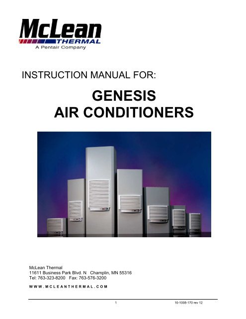
INSTRUCTION MANUAL FOR:<br />
GENESIS<br />
AIR CONDITIONERS<br />
McLean Thermal<br />
11611 Business Park Blvd. N Champlin, MN 55316<br />
Tel: 763-323-8200 Fax: 763-576-3200<br />
W W W . M C L E A N T H E R M A L . C O M<br />
1 10-1008-170 rev 12
TABLE OF CONTENTS<br />
Receiving the Air Conditioner ..........................................................................1<br />
Handling and Testing the Air Conditioner ........................................................1<br />
<strong>Installation</strong> ........................................................................................................2<br />
Design Data, Drawings/Illustrations, Components List & Wire Diagrams<br />
Genesis TM 13.......................................................................................3<br />
Genesis TM 17.......................................................................................6<br />
Genesis TM 28.......................................................................................9<br />
Genesis TM 33NSM.............................................................................14<br />
Genesis TM 36N ..................................................................................17<br />
Genesis TM 52.....................................................................................20<br />
Genesis TM HB11................................................................................24<br />
Temperature Control......................................................................................28<br />
Principles of Operation...................................................................................28<br />
Maintenance...................................................................................................28<br />
Trouble Shooting............................................................................................30<br />
Declaration of Conformity...............................................................................32<br />
McLean Thermal Warranty ............................................................................33<br />
NOTE: Some of the information in this manual may not apply if a special unit was ordered. If additional<br />
drawings for a special unit are necessary, they have been inserted. Contact McLean Thermal if further<br />
information is required.<br />
RECEIVING THE AIR CONDITIONER<br />
Inspect the air conditioner. Check for concealed damage that may have occurred during shipment. Look<br />
for dents, scratches, loose assemblies, evidence of oil, etc. Damage evident upon receipt should be<br />
noted on the freight bill. Damage should be brought to the attention of the delivering carrier -- NOT to<br />
McLean Thermal -- within 15 days of delivery. Save the carton and packing material and request an<br />
inspection. Then file a claim with the delivering carrier.<br />
McLean Thermal cannot accept responsibility for freight damages; however, we will assist you in any way<br />
possible.<br />
HANDLING & TESTING THE AIR CONDITIONER<br />
If it is necessary to place the air conditioner in a horizontal position after unpacking, be certain it is placed<br />
in an upright, vertical or mounting position for a minimum of five (5) minutes before operating.<br />
Never attempt to operate the air conditioner while it is horizontal or on its side, back or front. The<br />
refrigeration compressor is filled with lubricating oil. Running the compressor without oil in the lower part<br />
of the housing will cause permanent damage to the air conditioner. This also voids the warranty.<br />
TEST FOR FUNCTIONALITY BEFORE MOUNTING THE AIR CONDITIONER TO THE ENCLOSURE.<br />
1 10-1008-170 rev 12
Refer to nameplate for proper electrical current requirements, then connect power cord to a properly<br />
grounded power supply. Minimum circuit ampacity should be at least 125% of the amperage shown in the<br />
design data section for the appropriate model. No other equipment should be connected to this circuit to<br />
prevent overloading.<br />
Operate the air conditioner for five (5) to ten (10) minutes. No excessive noise or vibration should be<br />
evident during this run period. The condenser blower (ambient air), the evaporator blower (enclosure air),<br />
and the compressor should be running.<br />
Condenser air temperatures should be warmer than normal room temperatures within a few minutes.<br />
The compressor is provided with automatic reset thermal overload protection. This thermo-switch is<br />
located and mounted inside the plastic enclosure clipped to the compressor. The switch operates when<br />
the compressor overheats due to clogged or dirty inlet air filter or if ambient air temperatures exceed<br />
nameplate rating or if enclosure dissipated heat loads exceed the rated capacity of the air conditioner.<br />
The thermal overload switch will actuate and stop compressor operation. The blowers will continue to<br />
operate and the compressor will restart after it has cooled to within the thermal overload cut-in<br />
temperature setting.<br />
INSTALLATION<br />
Step 1: Inspect air conditioner. Verify functionality before mounting the air conditioner, see Handling &<br />
Testing the Air Conditioner on page 1.<br />
Step 2: Using the cutout dimensions shown in this manual or the cutout template printed on the units<br />
shipping carton, prepare the air “IN” and air “OUT” openings, and mounting bolt hole pattern for the<br />
enclosure.<br />
Step 3: Using the gasket kit provided, install gaskets to air conditioner. See gasket kit illustration in this<br />
manual for proper location.<br />
Step 4: Mount air conditioner on enclosure using mounting bolts and screws provided. “EZ” mount tabs<br />
can be used to hold unit on enclosure while mounting in place. Allow unit to remain upright for a minimum<br />
of five (5) minutes before starting. Caution: Air conditioner must be in upright position during operation.<br />
Step 5: Refer to top of nameplate for electrical requirements. Connect the power cord to a properly<br />
grounded power supply. Use of an extension cord is not recommended. <strong>Electric</strong>al circuit should be fused<br />
with slow blow or HACR circuit breaker.<br />
2 10-1008-170 rev 12
GENESIS TM 13 Series<br />
1000 BTU/Hr. (293 Watts) H x W x D: 13.25" (337) x 14.25" (362) x 7.80" (198)<br />
Full BTU/Hr @ Max Shipping<br />
Load<br />
Max Amb Amb Temp Weight<br />
Model Voltage Hz Amps Phase Temp<br />
o F/ o C Lbs/Kgs<br />
M13-0116-G1014 STOCK 115 50/60 4.0/4.0 1 800/1000 125/52 48/22<br />
M13-0116-G1XXX 115 50/60 4.0/4.0 1 800/1000 125/52 48/22<br />
M13-0126-G1008 STOCK 230 50/60 2.2/2.1 1 800/1000 125/52 48/22<br />
M13-0126-G1XXX 230 50/60 2.2/2.1 1 800/1000 125/52 48/22<br />
-XXX will be replaced with a three-digit number designating all desired options. Consult the factory for<br />
specific model numbers..<br />
M13 Model Drawing<br />
M13 Mounting Gasket Kit<br />
M13 Mounting Cutout Dimensions<br />
3 10-1008-170 rev 12
M13 Series Components List<br />
Item Part Number (1000 BTU)<br />
Part Description No. 115 Volt 230 Volt<br />
Fan, Condenser 1 12-1012-01 12-1012-02<br />
Fan, Evaporator 2 13-1015-01 13-1015-02<br />
Capacitor, Compressor N/A N/A N/A<br />
Coil, Condenser 4 13-1001-05 13-1001-05<br />
Coil, Evaporator 5 13-1001-04 13-1001-04<br />
Compressor, AE 6 10-1016-61 10-1026-71<br />
Control Panel Assy, Narrow N/S 10-1106-100 10-1106-100<br />
Filter, Air, Reusable, Narrow N/S 10-1000-57 10-1000-57<br />
Filter/Dryer 7 52-6028-00 52-6028-00<br />
Grille, Front, Narrow N/S 10-1130-01 10-1130-01<br />
Hot Gas By-Pass Valve N/A N/A N/A<br />
Pan, Condensate 9 10-1130-12 10-1130-12<br />
Pan, Evaporator 10 10-1130-13 10-1130-13<br />
Relay, Compressor, Start 11 10-1028-00 10-1028-16<br />
Service Cord 12 52-6035-138 52-6035-139<br />
Terminal Block 13 10-1003-03 10-1003-03<br />
Thermal Overload, Compressor 14 10-1007-19 10-1007-58<br />
Thermostat, SPST, 55-100F 15 10-1061-16 10-1061-16<br />
Transformer, 10VAC Secondary 16 10-1006-114 10-1006-115<br />
M13 Components Drawing (Front <strong>View</strong>)<br />
4 10-1008-170 rev 12
M13 Wire Diagram, 115/230 Volt, 1000 BTU<br />
5 10-1008-170 rev 12
GENESIS TM 17 Series<br />
1800 BTU/Hr. (527 Watts) H x W x D: 17.65" (448) x 12" (305) x 8.68" (220)<br />
Full BTU/Hr @ Max Shipping<br />
Load<br />
Max Amb Amb Temp Weight<br />
Model Voltage Hz Amps Phase Temp<br />
o F/ o C Lbs/Kgs<br />
M17-0216-G009 STOCK 110/115 50/60 6.6/6.7 1 1500/1800 125/52 56/25<br />
M17-0216-GXXX 110/115 50/60 6.6/6.7 1 1500/1800 125/52 56/25<br />
M17-0226-G004 STOCK 220/230 50/60 4.2/3.7 1 1500/1800 125/52 56/25<br />
M17-0226-GXXX 220/230 50/60 4.2/3.7 1 1500/1800 125/52 56/25<br />
-XXX will be replaced with a three-digit number designating all desired options. Consult the factory for<br />
specific model numbers.<br />
M17 Model Drawing<br />
M17 Mounting Gasket Kit<br />
M17 Mounting Cutout Dimensions<br />
6 10-1008-170 rev 12
M17 Series Components List<br />
Item Part Number (1800 BTU)<br />
Part Description No. 115 Volt 230 Volt<br />
Fan, Condenser 1 12-1012-01 12-1012-02<br />
Fan, Evaporator 2 12-1012-01 12-1012-02<br />
Capacitor, Compressor, Start 3 N/A 10-1032-09<br />
Coil, Condenser 4 17-1001-00 17-1001-00<br />
Coil, Evaporator 5 17-1002-01 17-1002-01<br />
Compressor, AE 6 10-1016-22 10-1026-74<br />
Control Panel Assy, Narrow N/S 10-1106-100 10-1106-100<br />
Filter, Air, Reusable, Narrow N/S 10-1000-57 10-1000-57<br />
Filter/Dryer 7 52-6028-03 52-6028-03<br />
Grille, Front, Narrow N/S 10-1130-01 10-1130-01<br />
Pan, Condensate 9 10-1130-14 10-1130-14<br />
Pan, Evaporator 10 10-1130-18 10-1130-18<br />
Relay, Compressor, Start 11 10-1028-05 10-1028-07<br />
Service Cord 12 52-6035-138 52-6035-139<br />
Terminal Block 13 10-1003-03 10-1003-03<br />
Thermal Overload, Compressor 14 10-1007-44 10-1007-57<br />
Thermostat, SPST, 55-100F 15 10-1061-02 10-1061-02<br />
Transformer, 10VAC Secondary 16 10-1006-114 10-1006-115<br />
M17 Components Drawing (Front <strong>View</strong>)<br />
7 10-1008-170 rev 12
M17 Wire Diagram, 115 Volt, 1800 BTU<br />
M17 Wire Diagram, 230 Volt, 1800 BTU<br />
8 10-1008-170 rev 12
GENESIS TM 28 Series<br />
2000-6000 BTU/Hr. (586-1758 Watts) H x W x D: 28.50" (724) x 17" (432) x 11.33" (288)<br />
Full BTU/Hr @ Max Shipping<br />
Load<br />
Max Amb Amb Temp Weight<br />
Model Voltage Hz Amps Phase Temp<br />
o F/ o C Lbs/Kgs<br />
M28-0216-G013 STOCK 115 50/60 9.8/9.0 1 2200/2200 125/52 98/45<br />
M28-0216-GXXX 115 50/60 9.8/9.0 1 2200/2200 125/52 98/45<br />
M28-0226-G004 STOCK 230 50/60 5.0/4.5 1 2200/2200 125/52 98/45<br />
M28-0226-GXXX 230 50/60 5.0/4.5 1 2200/2200 125/52 98/45<br />
M28-0416-G007 STOCK 115 50/60 14.6/14.0 1 3800/4000 125/52 116/53<br />
M28-0416-GXXX 115 50/60 14.6/14.0 1 3800/4000 125/52 116/53<br />
M28-0426-G032 STOCK 230 50/60 7.4/6.9 1 3800/4000 125/52 116/53<br />
M28-0426-GXXX 230 50/60 7.4/6.9 1 3800/4000 125/52 116/53<br />
M28-0616-GXXX 115 50/60 16.4/17.2 1 5400/6000 125/52 120/55<br />
M28-0626-GXXX 230 50/60 8.0 1 5400/6000 125/52 120/55<br />
-XXX will be replaced with a three-digit number designating all desired options. Consult the factory for<br />
specific model numbers.<br />
M28 Model Drawing<br />
9 10-1008-170 rev 12
M28 Mounting Gasket Kit<br />
M28 Mounting Cutout Dimensions<br />
M28 Components Drawing (Front <strong>View</strong>)<br />
10 10-1008-170 rev 12
M28 Series Components List<br />
Item<br />
Part Number (115 Volt)<br />
Part Description No. 2200 BTU 4000 BTU 6000 BTU<br />
Blower, Condenser 1 30-4019-01M 30-4019-01M 38-2019-04<br />
Blower, Evaporator 2 28-1064-06M 28-1064-06M 28-1064-06M<br />
Capacitor, Compressor, Start/Run 3 N/A 10-1032-13 10-1032-15<br />
Coil, Condenser 4 24-1001-00 24-1001-00 24-1001-00<br />
Coil, Evaporator 5 28-1001-00 28-1001-01 14-1002-00<br />
Compressor, AE/AK/AK 6 10-1016-22 10-1016-26 10-1016-68<br />
Control Panel Assy, Wide N/S 10-1106-101 10-1106-101 10-1106-101<br />
Filter, Air, Reusable, Wide N/S 10-1000-56 10-1000-56 10-1000-56<br />
Filter/Dryer 7 52-6028-00 52-6028-00 52-6028-00<br />
Grille, Front, Wide N/S 10-1130-00 10-1130-00 10-1130-00<br />
Hot Gas By-Pass Valve 8 N/A 52-6027-16 52-6027-11<br />
Pan, Condensate 9 10-1130-17 10-1130-17 10-1130-17<br />
Pan, Evaporator 10 10-1130-15 10-1130-15 10-1130-15<br />
Relay, Compressor, Strart 11 10-1028-05 10-1028-14 N/A<br />
Service Cord 12 52-6035-138 52-6035-142 52-6035-125<br />
Terminal Block (If Installed) 13 10-1003-31 10-1003-31 10-1003-31<br />
Thermal Overload, Compressor 14 10-1007-44 10-1007-45 10-1007-50<br />
Thermostat, SPST, 55-100F 15 10-1061-16 10-1061-16 10-1061-16<br />
Transformer, 10VAC Secondary 16 10-1006-114 10-1006-114 10-1006-114<br />
Item<br />
Part Number (230 Volt)<br />
Part Description No. 2200 BTU 4000 BTU 6000 BTU<br />
Blower, Condenser 1 30-4019-02M 30-4019-02M 38-2020-04<br />
Blower, Evaporator 2 28-1064-05M 28-1064-05M 28-1064-05M<br />
Capacitor, Comp., Start/Start/Run 3 10-1032-09 10-1032-14 10-1032-18<br />
Coil, Condenser 4 24-1001-00 24-1001-00 24-1001-00<br />
Coil, Evaporator 5 28-1001-00 28-1001-01 14-1002-00<br />
Compressor, AE/AK/AK 6 10-1026-74 10-1026-77 10-1026-80<br />
Control Panel Assy, Wide N/S 10-1106-101 10-1106-101 10-1106-101<br />
Filter, Air, Reusable, Wide N/S 10-1000-56 10-1000-56 10-1000-56<br />
Filter/Dryer 7 52-6028-00 52-6028-00 52-6028-00<br />
Grille, Front, Wide N/S 10-1130-00 10-1130-00 10-1130-00<br />
Hot Gas By-Pass Valve 8 N/A 52-6027-16 52-6027-11<br />
Pan, Condensate 9 10-1130-17 10-1130-17 10-1130-17<br />
Pan, Evaporator 10 10-1130-15 10-1130-15 10-1130-15<br />
Relay, Compressor, Start 11 10-1028-07 10-1028-15 N/A<br />
Service Cord 12 52-6035-139 52-6035-139 52-6035-139<br />
Terminal Block (If Installed) 13 10-1003-31 10-1003-31 10-1003-31<br />
Thermal Overload, Compressor 14 10-1007-57 10-1007-51 10-1007-49<br />
Thermostat, SPST, 55-100F 15 10-1061-16 10-1061-16 10-1061-16<br />
Transformer, 10VAC Secondary 16 10-1006-115 10-1006-115 10-1006-115<br />
11 10-1008-170 rev 12
M28 Stock Wire Diagram, 115 Volt, 2200 BTU And 230 Volt 6000 BTU<br />
M28 Stock Wire Diagram, 230 Volt, 2200 BTU<br />
12 10-1008-170 rev 12
M28 Stock Wire Diagram, 115/230 Volt, 4000 BTU & 230 Volt 6000 BTU<br />
M28 Wire Stock Diagram, 115 Volt, 6000 BTU<br />
13 10-1008-170 rev 12
GENESIS TM 33NSM Series<br />
4000 BTU/Hr. (1172 Watts) H x W x D: 34.37" (873) x 12" (305) x 9.88" (251)<br />
Full BTU/Hr @ Max Shipping<br />
Load<br />
Max Amb Amb Temp Weight<br />
Model Voltage Hz Amps Phase Temp<br />
o F/ o C Lbs/Kgs<br />
M33-0416-G010 STOCK 115 50/60 13.0/13.2 1 3700/4000 125/52 105/48<br />
M33-0416-GXXX 115 50/60 13.0/13.2 1 3700/4000 125/52 105/48<br />
M33-0426-G009 STOCK 230 50/60 7.2/7.3 1 3700/4000 125/52 105/48<br />
M33-0426-GXXX 230 50/60 7.2/7.3 1 3700/4000 125/52 105/48<br />
-XXX will be replaced with a three-digit number designating all desired options. Consult the factory for<br />
specific model numbers.<br />
M33 Model Drawing<br />
14 10-1008-170 rev 12
M33 Mounting Gasket Kit<br />
M33 Mounting Cutout Dimensions<br />
M33 Wire Diagram, 115/230 Volt, 4000 BTU<br />
15 10-1008-170 rev 12
M33 Series Components List<br />
Item Part Number (4000 BTU)<br />
Part Description No. 115 Volt 230 Volt<br />
Blower, Condenser, Top Dischrg 1 38-2019-04 38-2020-04<br />
Blower, Condenser, Front Dischrg 1 38-2019-00 38-2020-00<br />
Fan, Evaporator 2 12-1012-01 12-1012-02<br />
Capacitor, Compressor, Start 3 10-1032-13 10-1032-14<br />
Coil, Condenser 4 33-2001-01 33-2001-01<br />
Coil, Evaporator 5 33-2002-02 33-2002-02<br />
Compressor, AK 6 10-1016-26 10-1026-77<br />
Control Panel Assy, Narrow N/S 10-1106-100 10-1106-100<br />
Filter, Air, Reusable, Narrow N/S 10-1000-57 10-1000-57<br />
Filter/Dryer 7 52-6028-00 52-6028-00<br />
Grille, Front, Narrow N/S 10-1130-01 10-1130-01<br />
Hot Gas By-Pass Valve 8 52-6027-16 52-6027-16<br />
Pan, Condensate 9 10-1130-17 10-1130-17<br />
Pan, Evaporator 10 10-1130-16 10-1130-16<br />
Relay, Compressor, Start 11 10-1028-14 10-1028-15<br />
Service Cord 12 52-6035-143 52-6035-141<br />
Terminal Block 13 10-1003-03 10-1003-03<br />
Thermal Overload, Compressor 14 10-1007-45 10-1007-51<br />
Thermostat, SPST, 55-100F 15 10-1061-16 10-1061-16<br />
Transformer, 10VAC Secondary 16 10-1006-114 10-1006-115<br />
M33 Components Drawing (Front <strong>View</strong>)<br />
16 10-1008-170 rev 12
GENESIS TM 36N Series<br />
6000 BTU/Hr. (1758 Watts) H x W x D: 38.72" (984) x 15" (381) x 11.33" (288)<br />
Full BTU/Hr @ Max Shipping<br />
Load<br />
Max Amb Amb Temp Weight<br />
Model Voltage Hz Amps Phase Temp<br />
o F/ o C Lbs/Kgs<br />
M36-0616-307 STOCK 115 50/60 14.0/14.0 1 5000/6000 125/52 120/54<br />
M36-0616-XXX 115 50/60 14.0/14.0 1 5000/6000 125/52 120/54<br />
M36-0626-306 STOCK 230 50/60 7.0/7.0 1 5000/6000 125/52 120/54<br />
M36-0626-XXX 230 50/60 7.0/7.0 1 5000/6000 125/52 120/54<br />
-XXX will be replaced with a three-digit number designating all desired options. Consult the factory for<br />
specific model numbers.<br />
M36 Model Drawing<br />
17 10-1008-170 rev 12
M36 Mounting Gasket Kit<br />
M36 Mounting Cutout Dimensions<br />
M36 Wire Diagram, 115/230 Volt, 6000 BTU<br />
18 10-1008-170 rev 12
M36 Series Components List<br />
Item Part Number (6000 BTU)<br />
Part Description No. 115 Volt 230 Volt<br />
Blower, Condenser 1 38-2019-04 38-2020-04<br />
Blower, Evaporator 2 28-1064-06M 28-1064-05M<br />
Capacitor, Compressor, Run 3 52-6031-01 52-6031-01<br />
Coil, Condenser 4 36-1017-01 36-1017-01<br />
Coil, Evaporator 5 28-1001-01 28-1001-01<br />
Compressor, AK 6 10-1016-08 10-1026-08<br />
Control Panel Assy, Wide N/S 10-1106-101 10-1106-101<br />
Filter, Air, Reusable, Wide N/S 10-1000-56 10-1000-56<br />
Filter/Dryer 7 52-6028-00 52-6028-00<br />
Grille, Front, Wide N/S 10-1130-00 10-1130-00<br />
Hot Gas By-Pass Valve 8 52-6027-00 52-6027-00<br />
Pan, Condensate 9 10-1130-17 10-1130-17<br />
Pan, Evaporator 10 10-1130-19 10-1130-19<br />
Relay, Compressor 11 N/A N/A<br />
Service Cord 12 52-6035-143 52-6035-141<br />
Terminal Block 13 10-1003-31 10-1003-31<br />
Thermal Overload, Compressor 14 10-1007-03 10-1007-11<br />
Thermostat, SPST, 55-100F 15 10-1061-16 10-1061-16<br />
Transformer, 10VAC Secondary 16 10-1006-114 10-1006-115<br />
M36 Components Drawing (Front <strong>View</strong>)<br />
19 10-1008-170 rev 12
GENESIS TM 52 Series<br />
6000-12000 BTU/Hr. (1758-3516 Watts) H x W x D: 52.63" (1337) x 17.13" (435) x 11.33" (288)<br />
Full BTU/Hr @ Max Shipping<br />
Load<br />
Max Amb Amb Temp Weight<br />
Model Voltage Hz Amps Phase Temp<br />
o F/ o C Lbs/Kgs<br />
M52-0616-XXX 115 50/60 13.0/13.0 1 5000/6000 125/52 155/70<br />
M52-0626-XXX 230 50/60 6.5/6.5 1 5000/6000 125/52 155/70<br />
M52-0816-032 STOCK 115 50/60 14.5/14.5 1 6700/8000 125/52 160/73<br />
M52-0816-XXX 115 50/60 14.5/14.5 1 6700/8000 125/52 160/73<br />
M52-0826-015 STOCK 230 50/60 8.0/8.0 1 6700/8000 125/52 160/73<br />
M52-0826-XXX 230 50/60 8.0/8.0 1 6700/8000 125/52 160/73<br />
M52-1016-038 STOCK 110/115 50/60 18.9/19.5 1 8300/10000 125/52 165/75<br />
M52-1016-XXX 110/115 50/60 18.9/19.5 1 8300/10000 125/52 165/75<br />
M52-1026-021 STOCK 220/230 50/60 9.5/9.8 1 8300/10000 125/52 165/75<br />
M52-1026-XXX 220/230 50/60 9.5/9.8 1 8300/10000 125/52 165/75<br />
M52-1216-017 STOCK 110/115 50/60 24.0/23.0 1 10000/12000* 125/52 175/79<br />
M52-1216-XXX 110/115 50/60 24.0/23.0 1 10000/12000* 125/52 175/79<br />
M52-1226-034 STOCK 220/230 50/60 12.2/11.6 1 10000/12000* 125/52 175/79<br />
M52-1226-XXX 220/230 50/60 12.2/11.6 1 10000/12000* 125/52 175/79<br />
-XXX will be replaced with a three-digit number designating all desired options. Consult the factory for<br />
specific model numbers.<br />
* Based on return air temperature slightly above ambient.<br />
M52 Model Drawing<br />
20 10-1008-170 rev 12
M52 Mounting Gasket Kit<br />
M52 Mounting Cutout Dimensions<br />
M52 Wire Diagram, 115 Volt, 10000 & 12000 BTU<br />
21 10-1008-170 rev 12
M52 Wire Diagram, 115/230 Volt, 6000 & 8000 BTU and 230 Volt, 10000 & 12000 BTU<br />
M52 Components Drawing (Front <strong>View</strong>)<br />
22 10-1008-170 rev 12
M52 Series Components List<br />
Item<br />
Part Number (115 Volt)<br />
Part Description No. 6000 BTU 8000 BTU 10000 BTU 12000 BTU<br />
Blower, Condenser 1 52-6034-10 52-6034-10 52-6034-10 52-6034-10<br />
Blower, Evaporator 2 52-6075-00 52-6075-00 52-6075-00 52-6034-10<br />
Capacitor, Compressor, Run 3 52-6031-01 52-6032-01 52-6032-01 52-6032-01<br />
Coil, Condenser 4 52-6111-00 52-6111-00 52-6111-00 52-6111-03<br />
Coil, Evaporator 5 28-1001-01 52-6002-02 52-6121-01 52-6121-01<br />
Compressor, AK 6 10-1016-08 10-1016-10 10-1016-12 10-1016-12<br />
Control Panel Assy, Wide N/S 10-1106-101 10-1106-101 10-1106-101 10-1106-101<br />
Filter, Air, Reusable, Wide N/S 10-1000-56 10-1000-56 10-1000-56 10-1000-56<br />
Filter/Dryer 7 52-6028-00 52-6028-00 52-6028-00 52-6028-00<br />
Grille, Front, Wide N/S 10-1130-00 10-1130-00 10-1130-00 10-1130-00<br />
Hot Gas By-Pass Valve 8 52-6027-00 52-6027-00 52-6027-00 52-6027-00<br />
Pan, Condensate 9 10-1130-17 10-1130-17 10-1130-17 10-1130-17<br />
Pan, Evaporator 10 10-1130-23 10-1130-23 10-1130-23 10-1130-23<br />
Contactor, Compressor, Start 11 N/A N/A 10-1005-41 10-1005-41<br />
Contactor Cover, Compressor 11 N/A N/A 10-1005-68 10-1005-68<br />
Service Cord 12 52-6035-142 52-6035-142 52-6035-125 52-6035-125<br />
Terminal Block 13 10-1003-31 10-1003-31 10-1003-31 10-1003-31<br />
Thermal Overload, Compressor 14 10-1007-03 10-1007-04 10-1007-05 10-1007-05<br />
Thermostat, SPST, 55-100F 15 10-1061-16 10-1061-16 10-1061-16 10-1061-16<br />
Transformer, 10VAC Secondary 16 10-1006-114 10-1006-114 10-1006-114 10-1006-114<br />
Item<br />
Part Number (230 Volt)<br />
Part Description No. 6000 BTU 8000 BTU 10000 BTU 12000 BTU<br />
Blower, Condenser 1 52-6025-10 52-6025-10 52-6025-10 52-6025-10<br />
Blower, Evaporator 2 52-6076-00 52-6076-00 52-6076-00 52-6025-10<br />
Capacitor, Compressor, Run 3 52-6031-01 52-6031-01 52-6031-01 52-6031-01<br />
Coil, Condenser 4 52-6111-00 52-6111-00 52-6111-00 52-6111-03<br />
Coil, Evaporator 5 28-1001-01 52-6002-02 52-6121-01 52-6121-01<br />
Compressor, AK 6 10-1026-08 10-1026-10 10-1026-12 10-1026-12<br />
Control Panel Assy, Wide N/S 10-1106-101 10-1106-101 10-1106-101 10-1106-101<br />
Filter, Air, Reusable, Wide N/S 10-1000-56 10-1000-56 10-1000-56 10-1000-56<br />
Filter/Dryer 7 52-6028-00 52-6028-00 52-6028-00 52-6028-00<br />
Grille, Front, Wide N/S 10-1130-00 10-1130-00 10-1130-00 10-1130-00<br />
Hot Gas By-Pass Valve 8 52-6027-00 52-6027-00 52-6027-00 52-6027-00<br />
Pan, Condensate 9 10-1130-17 10-1130-17 10-1130-17 10-1130-17<br />
Pan, Evaporator 10 10-1130-23 10-1130-23 10-1130-23 10-1130-23<br />
Relay, Compressor 11 N/A N/A N/A N/A<br />
Service Cord 12 52-6035-139 52-6035-139 52-6035-139 52-6035-141<br />
Terminal Block 13 10-1003-31 10-1003-31 10-1003-31 10-1003-31<br />
Thermal Overload, Compressor 14 10-1007-11 10-1007-12 10-1007-13 10-1007-13<br />
Thermostat, SPST, 55-100F 15 10-1061-16 10-1061-16 10-1061-16 10-1061-16<br />
Transformer, 10VAC Secondary 16 10-1006-115 10-1006-115 10-1006-115 10-1006-115<br />
23 10-1008-170 rev 12
GENESIS TM HB11 Series<br />
2000-4000 BTU/Hr. (586-1172 Watts) H x W x D: 10.25" (260) x 17" (432) x 21.02" (534)<br />
Full BTU/Hr @ Max Shipping<br />
Load<br />
Max Amb Amb Temp Weight<br />
Model Voltage Hz Amps Phase Temp<br />
o F/ o C Lbs/Kgs<br />
MHB11-0216-G306 STOCK 115 50/60 9.7/9.0 1 2200/2200 125/52 90/41<br />
MHB11-0216-G3XX 115 50/60 9.7/9.0 1 2200/2200 125/52 90/41<br />
MHB11-0226-G306 STOCK 230 50/60 5.5/4.6 1 2200/2200 125/52 90/41<br />
MHB11-0226-G3XX 230 50/60 5.5/4.6 1 2200/2200 125/52 90/41<br />
MHB11-0416-G307 STOCK 110/115 50/60 14.7/13.6 1 3300/4000 125/52 108/49<br />
MHB11-0416-G3XX 110/115 50/60 14.7/13.6 1 3300/4000 125/52 108/49<br />
MHB11-0426-G306 STOCK 220/230 50/60 8.0/7.5 1 3300/4000 125/52 108/49<br />
MHB11-0426-G3XX 220/230 50/60 8.0/7.5 1 3300/4000 125/52 108/49<br />
-XX will be replaced with a two-digit number designating all desired options. Consult the factory for<br />
specific model numbers.<br />
MHB11 Model Drawing<br />
MHB11 Mounting Gasket Kit<br />
MHB11 Mounting Cutout Dimensions<br />
24 10-1008-170 rev 12
MHB11 Series Components List<br />
Item Part Number (115 Volt) Part Number (230 Volt)<br />
Part Description No. 2200 BTU 4000 BTU 2200 BTU 4000 BTU<br />
Blower, Condenser 1 28-1064-06M 28-1064-06M 28-1064-05M 28-1064-05M<br />
Blower, Evaporator 2 28-1064-06M 28-1064-06M 28-1064-05M 28-1064-05M<br />
Capacitor, Compressor, Start 3 N/A 10-1032-13 10-1032-09 10-1032-14<br />
Coil, Condenser 4 11-3001-00 11-3001-00 11-3001-00 11-3001-00<br />
Coil, Evaporator 5 11-1002-00 11-1002-00 11-1002-00 11-1002-00<br />
Compressor, AE/AK/AE/AK 6 10-1016-22 10-1016-26 10-1026-74 10-1026-77<br />
Control Panel Assy, Wide N/S 10-1106-101 10-1106-101 10-1106-101 10-1106-101<br />
Filter, Air, Reusable, Wide N/S 10-1000-56 10-1000-56 10-1000-56 10-1000-56<br />
Filter/Dryer 7 52-6028-00 52-6028-00 52-6028-00 52-6028-00<br />
Grille, Front, Wide N/S 10-1130-00 10-1130-00 10-1130-00 10-1130-00<br />
Hot Gas By-Pass Valve 8 52-6027-16 52-6027-16 52-6027-16 52-6027-16<br />
Pan, Condensate 9 10-1130-24 10-1130-24 10-1130-24 10-1130-24<br />
Pan, Evaporator 10 10-1130-11 10-1130-11 10-1130-11 10-1130-11<br />
Relay, Compressor, Start 11 10-1028-05 10-1028-14 10-1028-07 10-1028-15<br />
Service Cord 12 52-6035-140 52-6035-143 52-6035-141 52-6035-141<br />
Terminal Block 13 10-1003-31 10-1003-31 10-1003-31 10-1003-31<br />
Thermal Overload, Compressor 14 10-1007-44 10-1007-45 10-1007-57 10-1007-51<br />
Thermostat, SPST, 55-100F 15 10-1061-16 10-1061-16 10-1061-16 10-1061-16<br />
Transformer, 10VAC Secondary 16 10-1006-114 10-1006-114 10-1006-115 10-1006-115<br />
MHB11 Components Drawing (Right Side <strong>View</strong>)<br />
25 10-1008-170 rev 12
MHB11 Wire Diagram, 115 Volt, 2200 BTU<br />
MHB11 Wire Diagram, 230 Volt, 2200 BTU<br />
26 10-1008-170 rev 12
MHB11 Wire Diagram, 115/230 Volt, 4000 BTU<br />
27 10-1008-170 rev 12
TEMPERATURE CONTROL<br />
The electromechanical thermostat is factory preset to 75oF/23oC. To change the temperature setting,<br />
remove the nylon plug from the back face of the unit. Use a standard screwdriver to adjust thermostat.<br />
For cooler temperatures turn clockwise, for warmer temperatures turn counterclockwise.<br />
PRINCIPLES OF OPERATION<br />
If electrical power to the air conditioner is interrupted and reapplied immediately, (within 3 to 5 seconds),<br />
the compressor may not restart due to the high back pressure of the compressor. It takes a minimum of<br />
one (1) minute after shutdown for the compressor suction and discharge pressures to equalize in order<br />
for the air conditioner to restart.<br />
Operating the air conditioner below the minimum ambient temperature or above the maximum ambient<br />
temperatures indicated on the nameplate voids all warranties.<br />
It is recommended that the warranty section of this manual be read in order to familiarize yourself with<br />
parameters of restricted operation.<br />
The moisture that the enclosure air can contain is limited. If moisture flows from the drain tube<br />
continuously this can only mean that ambient air is entering the enclosure. Be aware that frequent<br />
opening of the enclosure’s door admits humid air that the air conditioner must then dehumidify.<br />
MAINTENANCE<br />
Compressor<br />
The compressor requires no maintenance. It is hermetically sealed, properly lubricated at the factory and<br />
should provide years of satisfactory operating service.<br />
Should the refrigerant charge be lost, recharging ports (access fittings) on the suction and discharge<br />
sides of the compressor are provided for recharging and/or checking suction and discharge pressures.<br />
Under no circumstances should the access fitting covers be loosened, removed or tampered with.<br />
Breaking of seals on compressor access fittings during warranty period will void warranty on hermetic<br />
system.<br />
Recharging ports are provided for the ease and convenience of reputable refrigeration repair service<br />
personnel for recharging the air conditioner.<br />
Inlet Air Filter<br />
Proper maintenance of the inlet air filter, located behind the front grille, will assure normal operation of the<br />
air conditioner. If filter maintenance is delayed or ignored, the maximum ambient temperatures under<br />
which the unit is designed to operate will be decreased.<br />
If the compressor’s operating temperature increases above designed conditions due to a dirty or clogged<br />
filter (or plugged condenser coil), the air conditioner’s compressor will stop operating due to actuation of<br />
the thermal overload cutout switch located on the compressor housing. As soon as the compressor<br />
temperature has dropped to within the switch’s cut-in setting, the compressor will restart automatically.<br />
However the above condition will continue to take place until the filter has been cleaned or replaced.<br />
28 10-1008-170 rev 12
Inlet Air Filter Con’t<br />
It is recommended that power to the air conditioner be interrupted intentionally when abnormally high<br />
compressor operating temperature causes automatic shutdown of the unit. The above described<br />
shutdown is symptomatic of clogged or dirty filter, thus causing a reduction in cooling airflow across the<br />
surface of the compressor and condenser coil.<br />
Do not run the air conditioner for extended periods of time with the filter removed. Particles of dust, lint,<br />
etc., can plug the fins of the condenser coil, which will give the same reaction as a plugged filter. The<br />
condenser coil is not visible through the filter opening, so protect it with a filter.<br />
Continued operation under the above conditions can and will damage and shorten compressor life. The<br />
air conditioner features an easily removable inlet filter to facilitate necessary cleaning. There should be no<br />
reason to neglect this necessary maintenance.<br />
How To Remove, Clean or Install a New Inlet Air Filter<br />
RP aluminum washable air filters are designed to provide excellent filtering efficiency with a high dust<br />
holding capacity and a minimum amount of resistance to air flow. Because they are constructed entirely<br />
of aluminum they are lightweight and easy to service. Optimum filter performance is maintained by<br />
recoating the filters after washing with RP Super Filter Coat adhesive. To achieve maximum performance<br />
from your air handling equipment, air filters should be cleaned on a regular basis.<br />
The inlet air filter is located behind the front grille. To remove the grille, remove (2) screws and pull top<br />
edge of grille forward. The filter may now be removed and cleaned or new filter installed. Reinstall grille.<br />
Cleaning <strong>Instructions</strong>:<br />
1. Flush the filter with warm water from the exhaust side to the intake side. DO NOT USE CAUSTICS.<br />
2. After flushing allow filter to drain. Placing it with a corner down will assure complete drainage.<br />
3. Recoat the filters with RP Super Filter Coat adhesive. When spraying filter do so from both sides for<br />
maximum concentration of adhesive.<br />
Condenser and Evaporator Air Movers<br />
Blower and impeller motors require no maintenance. All bearings, shafts, etc. are lubricated during<br />
manufacturing for the life of the motor.<br />
If the condenser blower motor (ambient blower) should fail, it is not necessary to remove the air<br />
conditioner from the cabinet or enclosure to replace the blower. The condenser blower is mounted on its<br />
own bulkhead and is easily accessible by removing the front cover.<br />
Caution: Operation of the air conditioner in areas containing airborne caustics or chemicals can rapidly<br />
deteriorate filters, condenser coils, blowers and motors, etc. Contact McLean Thermal for special<br />
recommendations.<br />
Refrigerant Loss<br />
Each air conditioner is thoroughly tested prior to leaving the factory to insure against refrigeration leaks.<br />
Shipping damage or microscopic leaks not found with sensitive electronic refrigerant leak detection<br />
equipment during manufacture may require repair or recharging of the system. This work should only be<br />
performed by qualified professionals, generally available through a local, reputable air conditioning repair<br />
or service company.<br />
Refer to the data on the nameplate, which specifies the type of refrigerant and the charge size in ounces.<br />
Before recharging, make sure there are no leaks and that the system has been properly evacuated into a<br />
deep vacuum.<br />
29 10-1008-170 rev 12
TROUBLE SHOOTING<br />
Basic Air Conditioning Trouble Shooting Check List<br />
1. Check manufacturer’s nameplate located on the unit for correct power supply.<br />
2. Turn the power to the unit on. The evaporator (Enclosure or “COLD” air) blower should come on.<br />
Is there airflow<br />
YES, proceed to step # 3.<br />
NO, possible:<br />
Open motor winding<br />
Stuck blower motor<br />
Obstructed wheels/blades<br />
Repair or Replace<br />
defective part<br />
3. Check thermostat setting Adjust thermostat to the lowest setting. This should turn the condenser<br />
blower and the compressor on. Did condenser blower and compressor come on when the thermostat was<br />
turned on<br />
YES, proceed to step #4.<br />
NO, possible:<br />
Defective thermostat<br />
Replace part<br />
4. Are both blowers and the compressor running If not the unit will not cool properly.<br />
5. Check condenser (Ambient or “HOT” air) blower for airflow. Is there airflow<br />
YES, proceed to step # 6.<br />
NO, possible:<br />
Defective thermostat<br />
Open motor winding<br />
Stuck blower motor<br />
Obstructed wheels/blades<br />
Repair or Replace<br />
defective part<br />
6. Carefully check the compressor for operation - motor should cause slight vibration, and the outer<br />
case of the compressor should be warm.<br />
YES, wait 5 minutes, then proceed to step #7.<br />
NO, possible:<br />
Defective thermostat<br />
Defective capacitor<br />
Defective overload<br />
Defective relay<br />
Repair or Replace<br />
defective part<br />
7 Make sure the coils are clean. Then check evaporator “air in” and “air out” temperatures. If the<br />
temperatures are the same:<br />
Possible loss of refrigerant<br />
Possible bad valves in the compressor<br />
Repair or Replace<br />
defective part<br />
8. To check for a bad thermostat. Turn power to the unit off. Remove control box cover, place both<br />
thermostat wires onto one terminal (replace control box cover for safety). This will pass the switch in the<br />
thermostat. Turn the power on. If both blowers and the compressor come on, the thermostat needs to be<br />
replaced.<br />
30 10-1008-170 rev 12
Symptoms and Possible Causes:<br />
SYMPTOM<br />
Unit won’t cool<br />
POSSIBLE CAUSE<br />
* Blowers/impellers not running<br />
* Compressor not running<br />
* Compressor runs, but has bad valves<br />
* Loss of refrigerant<br />
Compressor tries to start but won’t run<br />
* Low line voltage at start. Should be +/-10% rated voltage<br />
* Compressor motor stuck<br />
* Bad relay<br />
* Bad overload switch<br />
* Bad run/start capacitor<br />
Unit blows breakers<br />
* Under sized breaker/fuse or not time delayed<br />
* Short in system<br />
Getting water in enclosure<br />
* Drain plugged<br />
* Drain tube kinked<br />
* Enclosure not sealed (allowing humidity in)<br />
For additional technical information (i.e., amp draw, pressures, temperatures)<br />
contact McLean Thermal at 763-323-8200.<br />
31 10-1008-170 rev 12
DECLARATION OF CONFORMITY<br />
Manufacturer<br />
Name:<br />
Address:<br />
McLean Thermal<br />
11611 Business Park Boulevard<br />
Champlin, Minnesota 55316<br />
and<br />
McLean Thermal Europe<br />
Unit 4 Bevan Way<br />
Smethwick, West Midlands<br />
England, B66 1BZ<br />
declare under our sole responsibility that the following products:<br />
<strong>Product</strong> Name:<br />
Model Numbers:<br />
Air Conditioner<br />
M13-XXXX-GXXXX<br />
M17-XXXX-GXXX<br />
M28-XXXX-GXXX<br />
M28-XXXX-XXX<br />
M33-XXXX-GXXX<br />
M36-XXXX-XXX<br />
M52-XXXX-XXX<br />
MHB11-XXXX-GXXX<br />
to which this declaration relates is in conformity with the following standards:<br />
Safety<br />
Specifications: EN 60335-1:1995<br />
EN 60335-2-40:1993<br />
following the provisions of:<br />
Low Voltage Directive 73/23/EEC<br />
EMC<br />
Specifications: CISPR 14:1993<br />
EN 55014:1993<br />
EN 55104:1995<br />
EN 61000-4-2:1995<br />
EN 61000-4-4:1995, 1kV to AC Line<br />
EN 61000-4-5:1995, 2kV to AC Line<br />
EN 61000-4-6:1996<br />
EN 61000-4-11:1995<br />
following the provision of:<br />
EMC Directive 89/366/EEC<br />
James Crolius<br />
Engineering Manager<br />
McLean Thermal<br />
February 1998<br />
32 10-1008-170 rev 12
McLEAN THERMAL WARRANTY<br />
Please note: Warranty effective at time of shipment.<br />
McLean Thermal warrants that all material and workmanship are free of defects in quality which impair<br />
the usefulness of the air conditioner or heat exchanger for a period of five (5) years for non-operating<br />
parts, except for the filter; and for one (1) year for everything else when installed and operated under the<br />
following conditions:<br />
A. Maximum voltage variation no greater than plus or minus 10% of nameplate nominal rating.<br />
B. Maximum frequency variation no greater than plus or minus 3 Hz. of nameplate nominal rating.<br />
C. Must not exceed minimum and maximum stated temperatures on the nameplate.<br />
D. Not to exceed (BTU/Hr.) rating, including any heat sink, as indicated on the nameplate.<br />
E. The unit must not be restarted for a period of one (1) minute after intentional or accidental<br />
shut-off. (This does not apply to heat exchanger or filter fan.)<br />
McLean Thermal warrants that all material and workmanship are free of defects in quality which impair<br />
the usefulness of the filter fan package and all custom air conditioners and heat exchangers for a period<br />
of one (1) year, except for the filter, when installed and operated under conditions A, B, C and D as listed<br />
above.<br />
Not covered in this warranty is damage to the air conditioner or heat exchanger due to the introduction of<br />
other than the nameplate-designated refrigerant. Operation of any McLean Thermal product that has not<br />
been designed with proper protective coatings and/or options and is in an abnormal or corrosive<br />
environment voids the warranty. Prolonged operation with dirty filters also voids the warranty.<br />
Should any part prove defective within the above warranty period, the customer may choose to return the<br />
defective product that is under warranty to McLean Thermal for repair at no charge or the customer has<br />
the option to repair the defective products at his own expense and McLean Thermal will supply repair<br />
parts at no charge providing the defective part is returned and found to have failed under warranty. Parts<br />
supplied as warranty replacement parts will assume the balance of the warranty on the part returned for<br />
warranty consideration.<br />
Please be advised: According to the Federal Register, no person maintaining, servicing, repairing, or<br />
disposing of appliances may knowingly vent or otherwise release into the environment any class I or class<br />
II substance used as refrigerant.<br />
McLean Thermal assumes no liability beyond the repair or replacement of its own product. Customer<br />
modification of any McLean Thermal product voids this warranty.<br />
The purchaser assumes the responsibility of grounding the unit and installing it in accordance with local<br />
electrical and safety codes, as well as the National <strong>Electric</strong> Code (NEC) and OSHA.<br />
This express warranty constitutes the entire warranty with respect to the PRODUCT and IS IN LIEU OF<br />
ALL OTHERS, EXPRESS OR IMPLIED, INCLUDING ANY WARRANTY OR MERCHANTABILITY AND<br />
WARRANTY OF FITNESS FOR A PARTICULAR PURPOSE AND IN NO EVENT IS MCLEAN<br />
THERMALRESPONSIBLE FOR ANY CONSEQUENTIAL DAMAGES OF ANY NATURE WHATSOEVER.<br />
HOLD HARMLESS<br />
In consideration of purchase of equipment from McLean Thermal by a customer, McLean Thermal agrees<br />
to indemnify and hold harmless such customer and users with a defense, as to any claim, demand,<br />
statutory court cost, fees for attorney's services provided for below, and/or judgment, for actual of alleged<br />
patent infringement in any country, arising out of the use, sale or advertisement of any equipment<br />
manufactured or sold by McLean Thermal to McLean Thermal’s own specifications, provided that the<br />
customer or user shall promptly notify McLean Thermal in writing of any such claim or demand, provided<br />
further that McLean Thermal shall have the right and option to undertake and control the entire defense of<br />
such claim, or demand instituted against the customer or user, but limited to the products made or sold by<br />
McLean Thermal, through counsel selected by McLean Thermal, and to settle and pay any claim award<br />
arising out of such claim or demand, and provided further that the customer or user will provide such<br />
information and assistance as McLean Thermal may request subject to reimbursement by McLean<br />
Thermal for any out-of pocket expense incurred in providing such requested assistance. Liability of<br />
McLean Thermal for any infringement or claim thereof shall be limited to the above undertaking.<br />
33 10-1008-170 rev 12