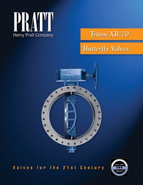
Triton XR-70 butterfly valve - Henry Pratt Company
Triton XR-70 butterfly valve - Henry Pratt Company
Triton XR-70 butterfly valve - Henry Pratt Company

Create successful ePaper yourself
Turn your PDF publications into a flip-book with our unique Google optimized e-Paper software.
Valves for the 21st Century page 1
A Tradition of Excellence<br />
With the development of the first rubber seated<br />
<strong>butterfly</strong> <strong>valve</strong> more than <strong>70</strong> years ago, the <strong>Henry</strong><br />
<strong>Pratt</strong> <strong>Company</strong> became a trusted name in the flow<br />
control industry, setting the standard for product<br />
quality and customer service. Today, <strong>Pratt</strong> provides<br />
the following range of superior products to the water,<br />
wastewater and power generation industries.<br />
Butterfly Valves: from 3" to 168"<br />
Rectangular Valves: 1’ x 1’ to 14’ x 16’<br />
Ball Valves —<br />
Rubber Seated: from 4" to 60"<br />
Metal Seated: from 6" to 48"<br />
Plug Valves: from 1/2" to 36", 3 ways<br />
Hydraulic Control Systems<br />
Valve Controls<br />
Energy Dissipating Valves<br />
and Fixed Energy Dissipaters<br />
Cone Valves<br />
Check Valves<br />
A Commitment to Meeting<br />
The Customers’ Needs<br />
<strong>Pratt</strong> <strong>valve</strong>s represent a long-term commitment to<br />
both the customer and to a tradition of product<br />
excellence. This commitment is evident in the number<br />
of innovations we have brought to the industries we<br />
serve. In fact, the <strong>Henry</strong> <strong>Pratt</strong> <strong>Company</strong> was the first<br />
to introduce many of the flow control products in use<br />
today, including the first rubber seated <strong>butterfly</strong> <strong>valve</strong>,<br />
one of the first nuclear N-Stamp <strong>valve</strong>s, and the<br />
bonded seat <strong>butterfly</strong> <strong>valve</strong>.<br />
Innovative Products<br />
For Unique Applications<br />
Though many of the standard <strong>valve</strong>s we produce are<br />
used in water filtration and distribution applica tions,<br />
<strong>Pratt</strong> has built a reputation on the ability to develop<br />
specialized products that help customers to meet<br />
their individual operational challenges.<br />
Creative Engineering<br />
for Fluid Systems<br />
<strong>Pratt</strong>’s ability to provide practical solutions to<br />
complex issues is demonstrated by the following<br />
case histories.<br />
Earthquake Proof Valves<br />
<strong>Pratt</strong> designed and manufactured hydraulically<br />
actuated <strong>valve</strong>s for a water storage application so<br />
that the <strong>valve</strong>s would automatically operate in the<br />
event of earthquakes. This led to the development of<br />
a <strong>valve</strong> that will withstand forces of up to 6g’s.<br />
Custom Actuation/<br />
Isolation Valves<br />
<strong>Pratt</strong> designed and manufactured <strong>valve</strong>s that would<br />
isolate a working chamber in the event of a nuclear<br />
emergency during the decommissioning of armed<br />
nuclear warheads. The <strong>valve</strong>s were able to close in<br />
a millisecond using specially designed <strong>Pratt</strong> electropneumatic<br />
actuators.<br />
Valves Designed for<br />
Harsh Environments<br />
<strong>Pratt</strong> designed and manufactured a 144" diameter<br />
<strong>butterfly</strong> <strong>valve</strong> for the emergency cooling system at<br />
a jet engine test facility. The <strong>valve</strong> was designed to<br />
supply water to help dissipate the tremen dous heat<br />
generated by the engines during testing.<br />
Through experience, commitment and creative engineering, <strong>Pratt</strong> is uniquely<br />
suited to provide superior products for our customers’ special needs.<br />
For more information, contact our corporate headquarters in Aurora, Illinois.<br />
page 2<br />
<strong>Henry</strong> <strong>Pratt</strong> <strong>Company</strong>
401 South Highland Avenue<br />
Aurora, Illinois 60506-5563<br />
www.henrypratt.com<br />
phone: 630.844.4000<br />
fax: 630.844.4160<br />
toll free: 877.436.7977<br />
Table Of Contents<br />
Scope of Line.......................................................................................2<br />
Features & Benefits.............................................................................3<br />
Design Details.................................................................................. 4-5<br />
E-Lok Seat Design...............................................................................6<br />
Flow Through Design..........................................................................6<br />
Coatings and Rubber Linings...............................................................7<br />
Water Flow Characteristics...............................................................8<br />
Valve End Types and Dimensions: Flanged End....................................9<br />
Valve End Types and Dimensions: Mechanical Joint End...................10<br />
Suggested Specifications for Butterfly Valves 24"<br />
and larg er Cast Construction..........................................................11<br />
Actuation...........................................................................................12<br />
Valves for the 21st Century page 1
Scope of Line<br />
<strong>Triton</strong> <strong>XR</strong>-<strong>70</strong> Butterfly Valve<br />
Sizes: 24 through 144 inches<br />
Standard Body Styles:<br />
- Flange x flange ends<br />
- Mechanical Joint ends (24"-48")<br />
- Flange and Mechanical Join ends (24", 30", 36")<br />
Standards:<br />
- Conforms to AWWA C504 requirements<br />
Pressure Class:<br />
- AWWA pressure classes 75B (54"-108") and 150B<br />
Seat: Rubber seat-in-body<br />
Actuation Options:<br />
- <strong>Pratt</strong> MDT manual ac tu a tor with AWWA nut,<br />
handwheel or chainwheel<br />
- Worm gear actuators<br />
- <strong>Pratt</strong> Dura-Cyl hydraulic or pneumatic cylinder<br />
Accessories/Options:<br />
Anti-cavitation device, bonnets, floorstands, lantern<br />
glands, shaft locking devices, external epoxy injection<br />
port, snubbers, expansion joints, rubber lining<br />
Consult factory for accessory details.<br />
Optional Body Styles:<br />
- Victaulic Ends<br />
- Concrete Pipe Ends<br />
Consult factory for lead times.<br />
Materials of Construction<br />
Standard<br />
Material<br />
Code<br />
542<br />
(<strong>XR</strong>-<strong>70</strong>)<br />
Type of Material<br />
Body Disc Disc Edge Shaft Bear ing<br />
Cast Iron Ductile Iron 316 S.S. 304 S.S. TLFB*<br />
Other materials available upon request<br />
*See material specifications table<br />
page 2<br />
<strong>Henry</strong> <strong>Pratt</strong> <strong>Company</strong>
Features and Benefits<br />
Feature<br />
Benefit<br />
E-Lok seat in design No hardware to loosen. Rubber not preloaded<br />
and uniform interference to provide long seat life.<br />
Foolproof adjustment and/or replacement (in most<br />
cases without re mov ing the <strong>valve</strong> from the line)<br />
Rubber seat located in body Reduces performance problems related to<br />
corrosive buildup in <strong>valve</strong> body and pipeline.<br />
Optional external injection port E-Lok seat can be adjusted and/or repaired<br />
in the field without dewatering the pipe line<br />
Seat material also available in EPDM Can accommodate tem per a tures up to 250<br />
degrees F<br />
Valve cycle tested per AWWA C504 requirements Proven reliability over the life of the <strong>valve</strong><br />
Flow through disc on 30 inch and larger More strength, less weight, greater free<br />
flow area. Higher C v : lower head loss results in<br />
energy savings for cus tom er’s system<br />
Nonmetallic bearings Prevents galvanic corrosion and provides<br />
lower coefficient of friction<br />
V-type shaft packing Self-adjusting, lasts the life of the <strong>valve</strong><br />
Through disc pinning Provides a tight disc-to-shaft pin connection,<br />
greatly reducing the possibility of loosening<br />
through vibration<br />
Specifications for<br />
Materials of Construction<br />
Body Material:<br />
Cast Iron — ASTM A126, Class B<br />
Disc Material:<br />
Ductile Iron — ASTM A536, Grade 65-45-12<br />
Disc Edge:<br />
Stainless Steel – ASTM A-240 Type 316<br />
Shaft Material:<br />
304 Stainless Steel — ASTM A276 Type 304<br />
Bearing Material:<br />
TLFB — Teflon lined, Fiberglass backed<br />
Valves for the 21st Century page 3
Design Details<br />
page 4<br />
<strong>Henry</strong> <strong>Pratt</strong> <strong>Company</strong>
Design Details<br />
1) Corrosion Resistant Shafts<br />
To prevent corrosion of a vital structural component, shafts<br />
are con struct ed of centerless ground ASTM A276 type<br />
304. This material is superior to car bon steel or similar<br />
materials that afford little protection against the harmful<br />
effects of cor ro sion. <strong>Pratt</strong>’s standard line consists of a twopiece,<br />
stub-type shaft keyed for the actuator connection.<br />
2) Packing and Packing Gland Assemblies<br />
Packing is self adjusting “V” type. The packing gland or<br />
shaft seal is uti lized only in the top trunnion of the <strong>valve</strong><br />
body where the shaft protrudes for actuator connection.<br />
The packing as sem bly incorporates a nylon pack ing<br />
re tain er accompanied by several rings of packing. Other<br />
available packing gland ar range ments include water seals<br />
(lantern glands) for pos i tive and negative pressures, and<br />
reverse “V” type for vacuum ap pli ca tions. Where access to<br />
packing is required, open-type bonnets can be pro vid ed.<br />
When this option is specified, “V” type packing is held in<br />
place with a bronze retaining gland which is fas tened to<br />
the <strong>valve</strong> trunnion with plated steel cap screws.<br />
3) Bearings<br />
Self-lubricating, sleeve-type bearings are used in both<br />
trun nions of the <strong>valve</strong> body. Bearings support the shaft<br />
and pro vide minimum friction during shaft rotation. Bear ing<br />
material is Teflon-lined with a special fi ber glass back ing.<br />
This type of bearing offers electrical insulating qual i ties<br />
between the disc/shaft assembly and the <strong>valve</strong> body,<br />
thereby diminishing the effects of galvanic corrosion. In<br />
addition, its reduced co ef fi cient of friction requires far less<br />
torque than the metallic bear ing materials.<br />
4) Rubber Seat<br />
The multi-ridge surface of <strong>Pratt</strong>’s E-Lok seat seals a full<br />
360˚ against a stainless steel spherical disc edge. Be cause<br />
of the laterally spaced grooves, rubber stress is sub stantial<br />
ly reduced, resulting in less sealing torque. The grooved<br />
seat design, coupled with the wide spher i cal ly shaped<br />
seating edge of the disc, also allows greater disc closure<br />
tolerance. Regardless of <strong>valve</strong> size, angular misposition of<br />
the disc can be 1˚ off center without leakage. The seat is<br />
mechanically retained by a unique ep oxy in jec tion process<br />
which moves the seat against the disc to conform to the<br />
exact radius of the disc with uni form con tact pressure.<br />
It is fully adjustable by local epoxy in jec tion and can be<br />
replaced in the field. As an option, <strong>valve</strong>s may be purchased<br />
with an ex ter nal in jec tion port which allows seat<br />
adjustment and repair to be performed with out re mov ing<br />
the <strong>valve</strong> or de w a ter ing the pipeline. For additional in forma<br />
tion regarding the E-Lok seat, refer to the “E-Lok Seat<br />
Design” section of this brochure.<br />
5) Shaft Connection<br />
Disc-to-shaft connection is accomplished by<br />
conservative ly sized stainless steel or monel taper pins,<br />
threaded at one end and secured with lockwashers and<br />
nuts. On 24 inch <strong>valve</strong>s, stainless steel dowel pins are<br />
used. <strong>Pratt</strong>’s through-pin design provides the tightest<br />
possible con nec tion between the shaft and disc.<br />
6) Valve Disc<br />
<strong>Pratt</strong> <strong>valve</strong> discs are constructed of the high est strengthto-weight<br />
ra tio materials available. On our 24 inch <strong>valve</strong>,<br />
the arch side of the disc is closed and the flat side is open,<br />
forming a slightly concave surface. On <strong>valve</strong>s 30 inches<br />
and greater, a flow through disc design is em ployed to<br />
minimize line tur bu lence and lower head loss. The great er<br />
free flow area pro vides less pres sure drop in the full-open<br />
position than other disc shapes. For ad di tion al in for ma tion<br />
re gard ing <strong>Pratt</strong>’s flow through disc de sign, refer to “Flow<br />
through Design” section of this brochure.<br />
7) Valve Body<br />
The bodies of the <strong>XR</strong>-<strong>70</strong> are constructed of heavy cast<br />
iron ASTM A126. On flange end bod ies, flange drilling<br />
is provided in ac cor dance with ANSI B16.1 for cast iron<br />
flanges through 72 inches. Larger sizes where applicable<br />
per AWWA C207.<br />
8) Thrust Bearing Assembly<br />
The two-way thrust bearing is preset at the factory. On<br />
<strong>valve</strong>s 30 inches and larger, the thrust bearing assembly<br />
consists of a stainless steel or monel stud fastened to the<br />
bottom of the <strong>valve</strong> shaft. The stud extends beyond the<br />
bottom cover. The thrust collar is threaded to the stud and<br />
pinned. On the 24 inch <strong>valve</strong>, the thrust collar is pinned to<br />
the shaft and fitted with bronze spacers. The bottom cover<br />
cap is then bolted to the bot tom cover and retains the<br />
thrust collar which, in turn, retains the position of the disc<br />
assembly. The cavity con tain ing the thrust collar is packed<br />
with grease providing lifetime lubrication of the thrust<br />
bearing assembly. The cap is fully gasketed to prevent<br />
leakage.<br />
Valve End Connection Options<br />
A wide range of <strong>valve</strong> end con nec tion options for the <strong>Pratt</strong><br />
<strong>Triton</strong> <strong>XR</strong>-<strong>70</strong> are available. See “Valve End Types and<br />
Dimensions” section for details.<br />
Actuation Options<br />
See “Actuation” section for <strong>Pratt</strong> actuators or refer to<br />
<strong>Pratt</strong>’s Actuator brochure for the many ac tu a tion op tions<br />
available for the Tri ton <strong>XR</strong>-<strong>70</strong>.<br />
Valves for the 21st Century page 5
E-Lok Seat Design<br />
Years of Reliable Service<br />
The <strong>Triton</strong> <strong>XR</strong>-<strong>70</strong> uti lizes the unique and patented*<br />
E-Lok seat-in-body design. With years of reliable<br />
performance, the E-Lok’s seat retention system<br />
still remains one of the most in no va tive con cepts in<br />
<strong>butterfly</strong> <strong>valve</strong> seat de sign. This design is often imitated<br />
without the superior results that only <strong>Pratt</strong> experience<br />
can deliver.<br />
How the E-Lok Seat Provides Bubble-Tight Closure<br />
The rubber seat, which is mount ed in the <strong>valve</strong> body,<br />
seals a full 360˚ against a stainless steel disc edge<br />
with low torque and high tol er ance to seating angle.<br />
The ridg es molded into the seat surface greatly reduce<br />
the pos si bil i ty of the seat being over compressed and<br />
minimizes compression set of rubber. In man u fac tur ing,<br />
a two part epoxy com pound is injected into a channel<br />
behind the rub ber seat with the disc in the closed<br />
position. This ensures equal interference around the<br />
complete circumference of the disc/seat contact area.<br />
The epoxy hardens, bonding neither to the met al seat<br />
channel nor to the rubber seat, yet me chan i cal ly re tains<br />
the seat in the body. Since the seat is installed and<br />
remains in a “relaxed” state, the possibility of damaging<br />
the seat is greatly reduced as compared to a seat that<br />
is “stressed” when bolted on to a body or disc as in<br />
other designs.<br />
Easy Seat Replacement<br />
In the unlikely event that seat replacement is required,<br />
it can be performed on <strong>valve</strong>s 30 inch es and larger<br />
with out re mov ing the <strong>valve</strong> from the pipeline (as long<br />
as a tech ni cian can access inside the <strong>valve</strong>), on all<br />
sizes with out re mov ing the shaft and/or disc. The<br />
original rub ber seat and hardened epoxy com pound<br />
used to retain the seat can be removed from the <strong>valve</strong><br />
with ordinary hand tools. A re place ment seat can then<br />
be installed, re turn ing the <strong>valve</strong> to its original bubble<br />
tight condition.<br />
Flow Through Design<br />
The <strong>Triton</strong> disc design distributes material where it<br />
is need ed to resist loads, achieving more strength at<br />
less weight than any other disc design currently on<br />
the mar ket. The flow through disc has a greater free<br />
flow area than conventional lens-shaped or offset disc<br />
designs, resulting in lower pumping costs.<br />
During injection, the seat is moved against the disc<br />
as the epoxy fills the cavity to provide uni form discto-seat<br />
interference around the en tire seating surface.<br />
The re sult is the bub ble tight closure. This system<br />
eliminates con ven tion al seat retention hardware that<br />
can loosen and corrode, potentially damaging pumps<br />
and other costly auxiliary equipment.<br />
Simple Seat Adjustment<br />
Another significant feature of the E-Lok seat is that it<br />
can be easily adjusted or re placed in the field while<br />
the <strong>valve</strong> is installed in the line. Ad just ment is achieved<br />
by local injection of ep oxy directly through the seat<br />
material into the chan nel be hind the seat. The epoxy<br />
travels the cir cum fer ence of the <strong>valve</strong> body channel<br />
until it finds the void and moves the seat ma te ri al<br />
outward toward the disc edge, bringing the <strong>valve</strong> back<br />
into bubble tight condition. If the <strong>valve</strong> was supplied<br />
with the op tion al** ex ter nal in jec tion port, the seat<br />
can be adjusted from the out side of the <strong>valve</strong> without<br />
SPHERE<br />
OF CONTACT<br />
DISC<br />
SEAT<br />
CAST<br />
EPOXY<br />
METAL TO METAL<br />
CLEARANCE<br />
UP TO 1/4"<br />
de wa ter ing the pipe line.<br />
The injection process can<br />
be achieved by utilizing<br />
simple tools and an<br />
in expen sive, dis pos able<br />
seat in jec tion kit.<br />
* U.S. Patent Nos. 3,304,050 and 3,418,411<br />
** U.S. Patent No. 5,538,029<br />
page 6<br />
<strong>Henry</strong> <strong>Pratt</strong> <strong>Company</strong>
Coatings and Rubber Linings<br />
Withstanding Harsh Conditions<br />
and the Test of Time<br />
In many industrial facilities, <strong>valve</strong>s are reg u lar ly<br />
subject ed to harsh conditions, in clud ing re cir cu lat ing<br />
wa ter loops where cor ro sive ness in creas es each time<br />
the water pass es through the sys tem, and cooling<br />
water sys tems which utilize brack ish wa ter or salt<br />
wa ter as a me di um. This is especially true at fossil and<br />
nu cle ar pow er gen er at ing plants, which fre quent ly use<br />
sea water as their main cooling wa ter resource.<br />
To com bat the damaging effects of these harsh<br />
condi tions, <strong>Pratt</strong> utilizes epoxy coatings and rub ber<br />
linings in conjunction with superior design fea tures to<br />
help ensure that the <strong>Triton</strong> <strong>XR</strong>-<strong>70</strong> <strong>butterfly</strong> <strong>valve</strong>s will<br />
withstand the test of time.<br />
The unique construction of the <strong>Pratt</strong> <strong>Triton</strong> rub ber<br />
seated <strong>butterfly</strong> <strong>valve</strong> makes both epoxy coatings and<br />
rubber lin ings much more ef fec tive than other <strong>butterfly</strong><br />
<strong>valve</strong> de signs. Since all surfaces of the <strong>Triton</strong> disc<br />
are exposed, there is no possibility for corrosion to<br />
start in hidden, un pro tect ed areas like the inside of a<br />
hollow, lens-shaped offset disc. Since there is no seat<br />
retention hardware, coating and/or lining breakdown<br />
in this area is also elim i nat ed.<br />
In applications involving salt water and/or en trained<br />
sol ids which can cause erosion, the su pe ri or i ty of<br />
rubber lining on the <strong>valve</strong> disc has been clearly<br />
demonstrated by <strong>Pratt</strong> but ter fly <strong>valve</strong>s placed in<br />
service decades ago that are still providing bubble<br />
tight closure today. Both ep oxy coat ing and rubber<br />
lin ing have also suc cess ful ly pro tect ed the<br />
<strong>valve</strong> bodies in these corrosive ser vice con di tions<br />
as illustrated by <strong>Pratt</strong>’s long track record of quality<br />
and re li abil i ty at in dus tri al facilities and power plants<br />
around the world.<br />
Rubber Linings<br />
<strong>Pratt</strong> lines corrosion-susceptible surfaces with a<br />
3<br />
⁄16-inch thick rubber of 60 Shore A durom e ter. The<br />
surfaces are prepared and blasted to a near- white<br />
metal finish. The linings are ap plied by the “hand-layup-meth<br />
od” (similar to tank lining techniques) and<br />
then cured in an open steam autoclave using 40 to 50<br />
psig steam pres sure. Following application and curing,<br />
the linings are vi su al ly inspected for air bubbles and<br />
checked at 7,000 volts with a positive control highvolt<br />
age spark tester.<br />
Epoxy Coatings<br />
<strong>Pratt</strong> has an extensive coating facility which ap plies<br />
and cures coatings in a controlled en vi ron ment.<br />
Prior to ap pli ca tion of the epoxy, <strong>valve</strong>s are sandblast<br />
ed and thoroughly cleaned to ensure a prop er<br />
bond. The in te ri or and external sur fac es of each <strong>valve</strong><br />
are coated with a Polya mide-cured, rust inhibiting<br />
epoxy, NSF ap proved. A mag net ic dry film thickness<br />
gauge is used to con firm that the coat ing thick ness<br />
match es the project/or der spec i fi ca tion re quire ments.<br />
Electron ic test ing for pin holes (hol i days) is per formed.<br />
3/16" RUBBER<br />
Other rubber lining features include <strong>Pratt</strong>’s shaftbearing<br />
being thor ough ly pro tect ed by rubber shaft<br />
seals to maintain bearing performance throughout the<br />
life of the <strong>valve</strong>. Also, the shaft bore in disc is sealed<br />
with a rubber seal. The juncture of the rubber liner to<br />
the rubber seat is also protected by a sealant applied<br />
under pressure.<br />
LINING<br />
CORROSION-RESISTANT<br />
DISC EDGE<br />
LINING<br />
Complete coverage of corrosion<br />
susceptible wetted surfaces is<br />
demonstrated in these drawings.<br />
Body lining in conjunction with<br />
the seat creates a water barrier<br />
and protects against corrosion.<br />
Valves for the 21st Century page 7
Water Flow Characteristics<br />
Proven Performance<br />
During its product development phase, the <strong>Triton</strong> <strong>butterfly</strong> <strong>valve</strong> was test ed to en sure that it met our own<br />
rigorous standards for flow ca pac i ty. The Tri ton but ter fly <strong>valve</strong> con sis tent ly pro duced high C v values which<br />
trans lates to low er flow re sis tance, in turn, low er ing system operating costs to the user over the life of the <strong>valve</strong>.<br />
Full Open C v<br />
Valves<br />
<strong>Triton</strong> <strong>XR</strong>-<strong>70</strong><br />
Class 75B<br />
SIZE FLAT ARCH<br />
54 159289 161194<br />
60 196654 199005<br />
66 237951 240796<br />
72 283181 286567<br />
78 332345 336318<br />
84 385441 390049<br />
90 442471 447761<br />
96 503433 509452<br />
102 568329 575124<br />
108 637158 644776<br />
114 <strong>70</strong>9920 718407<br />
120 786615 796019<br />
132 951804 963183<br />
144 1132725 1146268<br />
Full Open C v Valves<br />
<strong>Triton</strong> <strong>XR</strong>-<strong>70</strong> Valves<br />
Class 150B<br />
SIZE FLAT ARCH<br />
24 25380 26378<br />
30 39657 41216<br />
36 59351 62447<br />
42 85899 891<strong>70</strong><br />
48 112195 116466<br />
54 141808 146563<br />
60 172343 176486<br />
66 208535 213548<br />
72 248174 254139<br />
78 291260 298261<br />
84 337793 345912<br />
90 387772 39<strong>70</strong>93<br />
96 441199 451803<br />
102 498072 510043<br />
108 558392 571813<br />
114 622159 637113<br />
120 689373 <strong>70</strong>5942<br />
132 834171 854190<br />
144 992697 1016557<br />
page 8<br />
<strong>Henry</strong> <strong>Pratt</strong> <strong>Company</strong>
Valve End Types and Dimensions: Flanged End<br />
NOMINAL VALVE SIZE<br />
G = BOLT CIRCLE<br />
C = FLANGE OD<br />
A<br />
B<br />
Note: TAPPED HOLES: “F” SIZE UNC-2B X “E” DEEP<br />
24" VALVE 4 HOLES 2 TOP & 2 BOTTOM<br />
30" & UP 8 HOLES 4 TOP & 4 BOTTOM<br />
EACH FLANGE<br />
D<br />
E<br />
Notes:<br />
Dimensions shown in inches.<br />
Size = Nominal <strong>valve</strong> size.<br />
For bolts smaller than 1 3 ⁄4 inches in diameter, bolt holes<br />
will be 1 ⁄8 inches larger than diameter of bolts. For bolts<br />
1 3 ⁄4 inches in diameter and larger, bolt holes will be 1 ⁄4<br />
inches larger than diameter of bolts. Dimensions and<br />
drilling of end flanges conform to ANSI B16.1 Standard for<br />
cast iron flanges.<br />
Allow 3 1 ⁄2 inches for thrust bearing removal.<br />
A, B = Apply to AWWA Classes 75A, 75B.<br />
AA, BB = Apply to AWWA Class 150B.<br />
F = Number and size of bolts. 125 lbs. standard. Holes in<br />
trunnion area are tapped, see note.<br />
Flanged End Dimensions<br />
Size A B AA BB C D E F G<br />
24 — — 18 5 ⁄8 18 3 ⁄8 32 8 1 7 ⁄8 20-1 1 ⁄4 29 1 ⁄2<br />
30 21 9 ⁄16 22 3 ⁄4 21 1 ⁄2 24 1 ⁄8 38 3 ⁄4 12 2 1 ⁄8 28-1 1 ⁄4 36<br />
36 25 1 ⁄16 26 1 ⁄2 25 7 ⁄16 28 46 12 2 3 ⁄8 32-1 1 ⁄2 42 3 ⁄4<br />
42 29 1 ⁄16 30 3 ⁄8 29 7 ⁄8 32 11 ⁄16 53 12 2 5 ⁄8 36-1 1 ⁄2 49 1 ⁄2<br />
48 32 5 ⁄16 34 5 ⁄8 34 1 ⁄16 36 7 ⁄8 59 1 ⁄2 15 2 3 ⁄4 44-1 1 ⁄2 56<br />
54 36 1 ⁄8 38 1 ⁄2 37 1 ⁄2 40 11 ⁄16 66 1 ⁄4 15 3 44-1 3 ⁄4 62 3 ⁄4<br />
60 39 5 ⁄8 42 1 ⁄16 41 3 ⁄4 45 3 ⁄16 73 15 3 1 ⁄8 52-1 3 ⁄4 69 1 ⁄4<br />
66 43 9 ⁄16 46 3 ⁄4 46 1 ⁄16 49 1 ⁄2 80 18 3 3 ⁄8 52-1 3 ⁄4 76<br />
72 46 15 ⁄16 55 5 ⁄8 50 53 1 ⁄8 86 1 ⁄2 18 3 1 ⁄2 60-1 3 ⁄4 82 1 ⁄2<br />
Valves for the 21st Century page 9
Valve End Types and Dimensions: Mechanical Joint End<br />
A<br />
B<br />
D<br />
E<br />
Notes:<br />
Dimensions shown in inches.<br />
Size = nominal <strong>valve</strong> size.<br />
Bolts, nuts, glands and gaskets not furnished unless<br />
otherwise specified in contract.<br />
This end style available in AWWA Class 150B only.<br />
Allow 3 1 ⁄2 inches for thrust bearing removal.<br />
F = Number and size of bolts.<br />
NOMINAL VALVE SIZE<br />
G = BOLT CIRCLE<br />
X= LAYING<br />
LENGTH<br />
C<br />
Installation Diagram<br />
Mechanical Joint End Dimensions<br />
Size A B C D E F G X<br />
24 18 5 ⁄8 18 3 ⁄8 31 9 ⁄16 13 1 ⁄4 1 5 ⁄8 16- 3 ⁄4 30 6 3 ⁄8<br />
30 21 1 ⁄2 24 1 ⁄8 39 18 1 13 ⁄16 20-1 36 7 ⁄8 10<br />
36 25 7 ⁄16 28 45 7 ⁄8 22 2 24-1 43 3 ⁄4 14<br />
42 29 7 ⁄8 32 3 ⁄4 53 22 2 28-1 1 ⁄4 50 5 ⁄8 14<br />
48 34 1 ⁄16 36 7 ⁄8 59 7 ⁄8 24 2 32-1 1 ⁄4 57 1 ⁄2 16<br />
page 10<br />
<strong>Henry</strong> <strong>Pratt</strong> <strong>Company</strong>
Suggested Specifications for Butterfly Valves 24"<br />
and larg er Cast Construction<br />
General<br />
All <strong>butterfly</strong> <strong>valve</strong>s shall be of the tight closing, rubber<br />
seated type and fully comply with the latest revision of<br />
AWWA Stan dard C504 and NSF61, where applicable. Valves<br />
shall be bubble-tight at rated pressures in either direction,<br />
and shall be satisfactory for applications involving throttling<br />
service and for applications requiring <strong>valve</strong> actuation af ter<br />
long periods of inactivity. Valve discs shall rotate 90˚ from<br />
the full open position to the tight shut position. Re gard less<br />
of <strong>valve</strong> size, angular misposition of disc can be up to 1˚ off<br />
center without leakage.<br />
The manufacturer shall have manufactured tight closing,<br />
rub ber seated <strong>butterfly</strong> <strong>valve</strong>s for a period of at least ten<br />
years. All <strong>valve</strong>s from 24" through 144" shall be the <strong>Triton</strong><br />
<strong>XR</strong>-<strong>70</strong> as man u fac tured by the <strong>Henry</strong> <strong>Pratt</strong> <strong>Company</strong> or an<br />
approved equal.<br />
Valve Body<br />
All <strong>valve</strong> bodies shall be cast iron ASTM A126, Class B,<br />
narrow body design. Flange drilling shall be in ac cordance<br />
with ANSI B16.1 standard for cast iron flanges. Body<br />
thickness shall be in strict accordance with AWWA C504<br />
where ap pli ca ble.<br />
Valve Disc<br />
All <strong>valve</strong> discs shall be constructed of ductile iron ASTM<br />
A536 with a stainless steel seating edge. The disc shall<br />
not have any hollow chambers that can entrap wa ter. All<br />
surfac es shall be visually inspected and mea sur able to<br />
assure all struc tur al members are at full disc strength. Disc<br />
and shaft con nec tion shall be made with stainless steel pins.<br />
Valve Shaft<br />
All shafts shall be turned, ground, polished and construct<br />
ed of ASTM A-276 Type 304 or Type 316 stainless<br />
steel. Shafts shall be two-piece, stub type and keyed for<br />
ac tu a tor connection. Shaft di am e ters shall meet minimum<br />
re quirements established by the latest revision of AWWA<br />
Standard C504 for their class, where applicable.<br />
Valve Seat<br />
All seats shall be constructed of synthetic rubber compound<br />
such as Buna N or EPDM and suitable for bi di rection al<br />
shutoff at rated pressure. Seats shall be retained in the<br />
<strong>valve</strong> body by mechanical means with out re tain ing rings,<br />
segments, screws or hardware of any kind in the flow<br />
stream. Seats shall be a full 360˚ with out interruption and<br />
have a plu ral i ty of grooves mating with a spher i cal disc<br />
edge seating sur face. Valve seats shall be field ad just able<br />
around the full 360˚ circumference and re place able with out<br />
dis mantling the ac tu a tor, disc or shaft and without re mov ing<br />
the <strong>valve</strong> from the line.<br />
Valve Bearings<br />
All <strong>butterfly</strong> <strong>valve</strong>s shall be fitted with sleeve-type bearings.<br />
Bearings shall be corrosion resistant and self-lu bri cating.<br />
Bear ing load shall not exceed 1 ⁄5 of the com press ible<br />
strength of the bearing or shaft material.<br />
Valve Actuator<br />
Valve actuators shall conform to AWWA Standard C504<br />
and shall be designed to hold the <strong>valve</strong> in any in ter me di ate<br />
po sition between full open and fully closed without creeping<br />
or flut ter ing.<br />
Painting<br />
All surfaces of the <strong>valve</strong> shall be clean, dry and free from<br />
grease before applying paint or coating. The <strong>valve</strong> in te ri or<br />
and ex te ri or surfaces, except for the seating sur fac es, shall<br />
be pro vid ed with the manufacturer’s standard coating un less<br />
otherwise spec i fied by contract.<br />
Testing<br />
Hydrostatic and leakage tests shall be conducted in strict<br />
ac cor dance with AWWA Standard C504.<br />
Proof of Design<br />
The manufacturer furnishing the <strong>valve</strong>s under the<br />
specification shall be prepared to show proof that the <strong>valve</strong>s<br />
provided meet the design requirements of AWWA Stan dard<br />
C504.<br />
Typical Applications for <strong>Triton</strong> <strong>XR</strong>-<strong>70</strong><br />
Thousands of <strong>Triton</strong> <strong>XR</strong>-<strong>70</strong> but ter fly <strong>valve</strong>s have<br />
been installed in plants and in dus tri al fa cil i-<br />
ties around the world. Some typ i cal ap pli ca tions<br />
include the following:<br />
Water treatment<br />
Pumping sta tions<br />
Wastewater treatment Reservoirs<br />
Cooling water systems Pipelines<br />
Circulating water sys tems<br />
Nuclear, fossil fuel and cogeneration power plants<br />
Valves for the 21st Century page 11
Actuation<br />
Traveling Nut Type Manual Actuator<br />
The <strong>Pratt</strong> MDT manual compound lever-traveling nut type actuator is the ideal manual actuation option for the<br />
<strong>Triton</strong> <strong>XR</strong>-<strong>70</strong> <strong>butterfly</strong> <strong>valve</strong>. The MDT provides characterized closure, minimizing the possibility of line shock by<br />
slowing down the <strong>valve</strong> travel as the <strong>valve</strong> disc approaches the closed position. The high input torque capacity<br />
(450 foot pound maximum and a 200 pound pull on the handwheel or chainwheel) provides inherent protection<br />
from actua tor misuse.<br />
The <strong>Pratt</strong> MDT actuator is self locking without a unidirectional sustained force from the <strong>valve</strong>. It can be relied<br />
upon to maintain exact <strong>valve</strong> position under conditions of fluctuating, turbulent and intermittent flow.<br />
Completely in conformity to the latest revision of AWWA Standard C504, the <strong>Pratt</strong> <strong>Triton</strong> <strong>valve</strong>, coupled with<br />
the MDT actuator, offers single source responsibility and reliability for both actuator and <strong>valve</strong>. To ensure that<br />
we can meet the delivery requirements of our valued customers, <strong>Pratt</strong> maintains an inventory of selected <strong>valve</strong>s<br />
equipped with MDT actuators. Consult factory for availability.<br />
Chainwheel<br />
Handwheel<br />
MDT Mounting Positions<br />
M<br />
2" St’d.<br />
AWWA Nut<br />
W=<br />
DIA.<br />
V=<br />
DIA.<br />
N<br />
CLOSED<br />
OPEN<br />
PRATT<br />
P<br />
PRATT<br />
OPEN<br />
PRATT<br />
OPEN<br />
Q<br />
S<br />
T<br />
R<br />
Spur Gear<br />
End Cover<br />
Standard<br />
Position<br />
Alternate<br />
Position<br />
J<br />
L<br />
Notes:<br />
Clockwise to close (open left) unless otherwise specified.<br />
Spur gear and end cover apply only to MDT6S.<br />
MDT<br />
Dimensions<br />
Size J L M N P Q R S T V W<br />
MDT-3 7 3 ⁄4 4 1 ⁄16 3 1 ⁄4 3 5 ⁄22 5 5 ⁄8 5 3 ⁄8 9 1 ⁄4 10 1 ⁄2 10 12 9 1 ⁄8<br />
MDT-4 8 4 1 ⁄2 3 3 ⁄8 4 7 5 ⁄16 6 3 ⁄4 10 1 ⁄2 11 1 ⁄2 11 12 9 1 ⁄8<br />
MDT-5 10 5 5 ⁄8 4 1 ⁄2 5 1 ⁄2 8 3 ⁄4 10 1 ⁄2 17 17 1 ⁄8 17 7 ⁄8 18 16 7 ⁄16<br />
MDT-5S 10 3 ⁄4 6 1 ⁄8 5 5 ⁄8 7 10 5 ⁄8 15 15 ⁄16 19 11 ⁄16 20 20 3 ⁄4 24 22 1 ⁄4<br />
MDT-6S 12 7 ⁄8 7 5 ⁄8 7 8 1 ⁄4 12 5 ⁄8 18 5 ⁄8 26 1 ⁄2 26 3 ⁄4 25 7 ⁄8 24 22 1 ⁄4<br />
* The <strong>Triton</strong> <strong>XR</strong>-<strong>70</strong> can be equipped with a wide range of cylinder actuators and electric motor<br />
actuators to meet your special operating requirements. Please consult our factory for additional<br />
in formation.<br />
page 12<br />
<strong>Henry</strong> <strong>Pratt</strong> <strong>Company</strong>
Notes<br />
Valves for the 21st Century page 13
PRATT PRODUCT GUIDE<br />
Model<br />
2FII<br />
<strong>Triton</strong> ®<br />
HP250<br />
<strong>Triton</strong> ®<br />
<strong>XR</strong><strong>70</strong><br />
Control<br />
Systems<br />
<strong>Triton</strong> ®<br />
XL<br />
Metal Seated<br />
Ball Valve<br />
Rectangular<br />
Plug<br />
Valve<br />
Rubber Seated<br />
Ball Valve<br />
Tilting Disc<br />
Check Valve<br />
Groundhog ®<br />
Valve<br />
Cone Valve<br />
Monoflange<br />
MKII<br />
Sleeve Valve<br />
Indicating<br />
Butterfly Valve<br />
UL & FM approved<br />
Check Valve<br />
N-Stamp Nuclear<br />
Butterfly Valve<br />
Compact Controllable<br />
Energy Dissipater<br />
©2009 <strong>Henry</strong> <strong>Pratt</strong> <strong>Company</strong><br />
Printed in the U.S.A.<br />
<strong>XR</strong><strong>70</strong>-0509<br />
PIVA Post Indicating<br />
Valve Assembly<br />
UL & FM approved<br />
<strong>Henry</strong> <strong>Pratt</strong> <strong>Company</strong><br />
401 South Highland Avenue<br />
Aurora, Illinois 60506-5563<br />
Toll Free 877-436-7977<br />
630-844-4000<br />
Fax 630-844-4160<br />
www.henrypratt.com<br />
ISO 9001: 2000 Certified