Modem Configuration Procedure - GeoSIG Ltd.
Modem Configuration Procedure - GeoSIG Ltd.
Modem Configuration Procedure - GeoSIG Ltd.

Create successful ePaper yourself
Turn your PDF publications into a flip-book with our unique Google optimized e-Paper software.
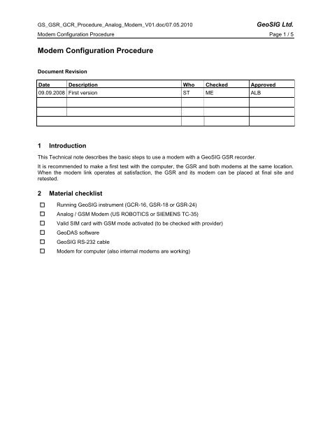
GS_GSR_GCR_<strong>Procedure</strong>_Analog_<strong>Modem</strong>_V01.doc/07.05.2010<br />
<strong>GeoSIG</strong> <strong>Ltd</strong>.<br />
<strong>Modem</strong> <strong>Configuration</strong> <strong>Procedure</strong> Page 1 / 5<br />
<strong>Modem</strong> <strong>Configuration</strong> <strong>Procedure</strong><br />
Document Revision<br />
Date Description Who Checked Approved<br />
09.09.2008 First version ST ME ALB<br />
1 Introduction<br />
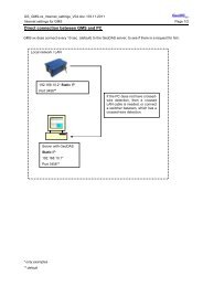
This Technical note describes the basic steps to use a modem with a <strong>GeoSIG</strong> GSR recorder.<br />
It is recommended to make a first test with the computer, the GSR and both modems at the same location.<br />
When the modem link operates at satisfaction, the GSR and its modem can be placed at final site and<br />
retested.<br />
2 Material checklist<br />
Running <strong>GeoSIG</strong> instrument (GCR-16, GSR-18 or GSR-24)<br />
Analog / GSM <strong>Modem</strong> (US ROBOTICS or SIEMENS TC-35)<br />
Valid SIM card with GSM mode activated (to be checked with provider)<br />
GeoDAS software<br />
<strong>GeoSIG</strong> RS-232 cable<br />
<strong>Modem</strong> for computer (also internal modems are working)
GS_GSR_GCR_<strong>Procedure</strong>_Analog_<strong>Modem</strong>_V01.doc/07.05.2010<br />
<strong>GeoSIG</strong> <strong>Ltd</strong>.<br />
<strong>Modem</strong> <strong>Configuration</strong> <strong>Procedure</strong> Page 2 / 5<br />
3 GSR side configuration<br />
The GSR should be pre-configured for normal operation using direct cable connection at 38400 bauds or the<br />
auto-bauds in the station configuration should be enabled.<br />
Using GeoDAS, connect the GSR station COM<br />
port to the GSR RS-232 connector<br />
Login to the GSR station<br />
Open the Instrument Setup Manager window<br />
Go to INSTRUMENT tab.<br />
Tick the ANALOG or GSM <strong>Modem</strong>:<br />
Press the PUT PAGE button to save the change.<br />
Acknowledge and warning message. Only if<br />
datastream, is enabled, the modem can not be<br />
set-<br />
Go to COMMUNICATION tab.<br />
Baudrate must be set to 38400 bauds:<br />
For a standard modem, the default string is:<br />
AT&FE0%C0&D0S0=1&W0&W1<br />
In case of US ROBOTICS modem, change the<br />
Initialization string to:<br />
AT&FE0&D0&H0S0=1&W0<br />
In case of GSM modem SIEMENS TC-35,<br />
change the Initialization -string to:<br />
AT&FE0V1&D0S0=1+CSNS=4&W<br />
Disable Auto-Dial. Refer to operating manual for a<br />
description of the use of auto-dial.
GS_GSR_GCR_<strong>Procedure</strong>_Analog_<strong>Modem</strong>_V01.doc/07.05.2010<br />
<strong>GeoSIG</strong> <strong>Ltd</strong>.<br />
<strong>Modem</strong> <strong>Configuration</strong> <strong>Procedure</strong> Page 3 / 5<br />
Press the PUT PAGE button to save the change.<br />
A message will come:<br />
“You are about to change the critical modem<br />
settings, which require the instrument to be<br />
restarted. Please note that you will be logged out<br />
automatically and the next login can be performed<br />
in several minutes only”.<br />
Check the LCD display of the GSR until it start to<br />
operate normally (reset is finished). Then press<br />
the button CONNECT:<br />
Additionally you can use the EXPORT button to<br />
save this new configuration under a name like<br />
station_name-modem.<br />
Review the settings.<br />
Logout b pressing the DISCONNECT button.<br />
Connect the modem to the GSR RS-232 connector<br />
Connect modem to T+T line or set antenna for a GSM modem.<br />
Connect power supply to modem and switch on modem<br />
Turn OFF GSR and ON again.<br />
Use special modem GSR cable<br />
<strong>Modem</strong> is initialized by GSR. It will load<br />
in modem the initialization string.<br />
4 PC side configuration<br />
Connect other <strong>Modem</strong> to T+T line<br />
Connect power supply to <strong>Modem</strong> and switch on<br />
<strong>Modem</strong><br />
Connect other <strong>Modem</strong> to PC<br />
Start GeoDAS<br />
In menu, select SETTINGS / CONFIGURE<br />
STATIONS.<br />
In the list, select your station and do a right click<br />
on its name. Select COMM CHANNEL:
GS_GSR_GCR_<strong>Procedure</strong>_Analog_<strong>Modem</strong>_V01.doc/07.05.2010<br />
<strong>GeoSIG</strong> <strong>Ltd</strong>.<br />
<strong>Modem</strong> <strong>Configuration</strong> <strong>Procedure</strong> Page 4 / 5<br />
Select DIAL-<br />
CONNECTION through<br />
a dedicated modem<br />
Select the COM port<br />
where the modem is<br />
attached to the PC.<br />
Update the modem<br />
initialization string. (see<br />
below)<br />
Enter here the phone<br />
number of the GSR<br />
station.<br />
Disable TRY ALL<br />
THE BAUDS RATE<br />
Select 38400 bauds<br />
Enter 5000 for<br />
the timeout.<br />
Disable auto-answer of the modem. This is<br />
related to the AUTODIAL function of the<br />
GSR.<br />
Initialization strings:<br />
GSR-18: AT&FE0V1S0=1&D0\Q2+CMGF=0^SSYNC=1+CSNS=4+IPR=19200&W<br />
GSR-24: AT&FE0V1&D0S0=1+CSNS=4&W or AT&FE0V1&D0S0=1+CSNS=4&W<br />
GCR-16: AT&FE0V1&D0S0=1+CSNS=4&W or AT&FE0V1&D0S0=1<br />
Review the configuration.<br />
Press the OK button.<br />
Press again OK in the station list window.<br />
A warning message indicates you that the<br />
GeoDAS program will have to restart<br />
according to the change you performed.<br />
Press YES button.<br />
The window will disappear.<br />
You should see now in the SERIAL<br />
COMMUNICATION CHANNELS a modem at<br />
the selected COM port.
GS_GSR_GCR_<strong>Procedure</strong>_Analog_<strong>Modem</strong>_V01.doc/07.05.2010<br />
<strong>GeoSIG</strong> <strong>Ltd</strong>.<br />
<strong>Modem</strong> <strong>Configuration</strong> <strong>Procedure</strong> Page 5 / 5<br />
5 Establish Link<br />
In the station list, select the station you<br />
configured for modem operation.<br />
Press the CONNECT button.<br />
Wait that the modem link is established.<br />
Check communication works well.<br />
Display the instrument setup manager<br />
window. Go to DATE AND TIME tab.<br />
Go to the TEST tab.<br />
Close the window by pressing the EXIT<br />
button.<br />
Open the EVENT MANAGER window<br />
Press the disconnect button.<br />
<strong>Modem</strong> dials and GSR <strong>Modem</strong> takes the call.<br />
The serial communication channels window will show for<br />
the modem the call progress.<br />
Check the CD lamp on the modem are on<br />
Check the modems LED’s for activity.<br />
Check that time is correct and updating.<br />
Try to record a sensor test. Be sure that RECORD A TEST<br />
PULSE is enabled.<br />
Download the sensor test you created.<br />
<strong>Modem</strong> hangs up automatically<br />
Note:<br />
For the same GSR, you can configure 2 stations, one for modem operation and one for direct link, but in<br />
such case, event data will be stored in 2 different directories.<br />
As alternative you can have all the GSR operating with modem having their own station and use only one<br />
station in case a direct connection is required (site visit). It is recommended to name such station TEMP. It<br />
will operate at 38400 bauds. After a site visit, all the data file in the TEMP station data directory will have to<br />
be manually moved to their respective station data directory.