AP031 Differential Probe Manual - Teledyne LeCroy
AP031 Differential Probe Manual - Teledyne LeCroy
AP031 Differential Probe Manual - Teledyne LeCroy

You also want an ePaper? Increase the reach of your titles
YUMPU automatically turns print PDFs into web optimized ePapers that Google loves.
Operator’s<br />
<strong>Manual</strong><br />
<strong>AP031</strong><br />
<strong>Differential</strong> <strong>Probe</strong>
© 2013 <strong>Teledyne</strong> <strong>LeCroy</strong>, Inc. All rights reserved.<br />
Unauthorized duplication of <strong>Teledyne</strong> <strong>LeCroy</strong> documentation materials other than for internal sales<br />
and distribution purposes is strictly prohibited. However, clients are encouraged to distribute and<br />
duplicate <strong>Teledyne</strong> <strong>LeCroy</strong> documentation for their own internal educational purposes.<br />
<strong>Teledyne</strong> <strong>LeCroy</strong> is a registered trademarks of <strong>Teledyne</strong> <strong>LeCroy</strong>, Inc. Windows is a registered<br />
trademark of Microsoft Corporation. Other product or brand names are trademarks or requested<br />
trademarks of their respective holders. Information in this publication supersedes all earlier versions.<br />
Specifications are subject to change without notice.<br />
922264-00 Rev A<br />
March 2013<br />
Warranty<br />
<strong>Teledyne</strong> Lecroy warrants this oscilloscope accessory for normal use and operation within specification for a period<br />
of one year from the date of shipment. Spare parts, replacement parts and repairs are warranted for 90 days.<br />
In exercising its warranty, <strong>Teledyne</strong> Lecroy, at its option, will either repair or replace any assembly returned within<br />
its warranty period to the Customer Service Department or an authorized service center. However, this will be<br />
done only if the product is determined by <strong>Teledyne</strong> Lecroy’s examination to be defective due to workmanship or<br />
materials, and the defect is not caused by misuse, neglect, accident, abnormal conditions of operation, or damage<br />
resulting from attempted repair or modifications by a non-authorized service facility.<br />
The customer will be responsible for the transportation and insurance charges for the return of products to the<br />
service facility. <strong>Teledyne</strong> Lecroy will return all products under warranty with transportation charges prepaid.<br />
This warranty replaces all other warranties, expressed or implied, including but not limited to any implied warranty<br />
of merchantability, fitness or adequacy for any particular purposes or use. <strong>Teledyne</strong> Lecroy shall not be liable for<br />
any special, incidental, or consequential damages, whether in contract or otherwise.
<strong>AP031</strong> <strong>Probe</strong><br />
Safety Instructions<br />
This section contains instructions that must be observed to keep this oscilloscope accessory<br />
operating in a correct and safe condition. You are required to follow generally accepted<br />
safety procedures in addition to the precautions specified in this section. The overall safety<br />
of any system incorporating this accessory is the responsibility of the assembler of the<br />
system.<br />
Symbols<br />
These symbols may appear on the probe body or in this manual to alert you to important<br />
safety considerations.<br />
HIGH VOLTAGE, risk of electric shock.<br />
CAUTION of potential for damage to probe or instrument it is connected to or WARNING<br />
of potential bodily injury. Attend to the accompanying information to protect against<br />
personal injury or damage. Do not proceed until conditions are fully understood and met.<br />
ELECTROSTATIC DISCHARGE (ESD) HAZARD. The probe is susceptible to damage if antistatic<br />
measures are not taken.<br />
ON (POWER)<br />
OFF (POWER)<br />
DOUBLE INSULATION<br />
MEASUREMENT GROUND TERMINAL<br />
2 922264-00 Rev A
Operator’s <strong>Manual</strong><br />
Precautions<br />
To avoid personal injury or damage to property, review and comply with the following<br />
safety precautions.<br />
Use product only as specified. The probe is designed to make differential voltage<br />
measurements. It is not to be used to insulate the circuit under test from the measuring<br />
instrument.<br />
Do not overload. To avoid electric shock or fire hazard, do not apply any potential that<br />
exceeds the maximum rating of the probe and/or the probe accessory (e.g. probe hooks),<br />
whichever is less.<br />
Connect and disconnect properly. To avoid electric shock or fire hazard, always make the<br />
connections from the probe input leads to the probe hooks before making any connections<br />
to a voltage source. Do not connect or disconnect probe hooks to a votage source unless<br />
they are first connected to the probe input leads. Ensure connections between probe input<br />
leads and probe hooks are secure before connecting them to a voltage source.<br />
Use only accessories compatible with the probe. Use only accessories that are shipped<br />
with the product. Substitution of other accessories may create a potential shock hazard.<br />
Comply with voltage derating curve. When measuring higher frequency signals, comply<br />
with the Voltage vs. Frequency Derating Curve (see Page 7).<br />
Observe all terminal ratings. To avoid electric shock or fire, do not use the probe above the<br />
input limits shown on the probe as well as all accessories.<br />
Do not remove probe casing. Removing the probe’s case or touching exposed connections<br />
may result in electric shock.<br />
Use only within operational environment listed. Do not use in wet or explosive<br />
atmospheres. Keep product surfaces clean and dry.<br />
922264-00 Rev A 3
<strong>AP031</strong> <strong>Probe</strong><br />
Avoid damage to cable through excessive bending.<br />
Handle with care. Tips of probe hooks are sharp. They puncture skin or cause other bodily<br />
injury if not handled properly.<br />
Keep fingers behind the finger guard of the probe hooks.<br />
Do not operate with suspected failures. Before each use, inspect the probe and probe<br />
hooks for any potential damage such as tears or other defects in the probe body, cable<br />
jacket, accessories, etc. If any part is damaged, cease operation immediately and sequester<br />
the probe from inadvertent use.<br />
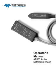
Introduction<br />
The <strong>AP031</strong> is a fully differential active probe designed for applications where electrical<br />
signals must be measured relative to a floating voltage different to the oscilloscope ground<br />
potential.<br />
This probe is specifically designed for situations where:<br />
<br />
<br />
<br />
The reference voltage may be several hundreds volts above or below ground.<br />
Measurements require the rejection of common mode signals.<br />
Ground loops and currents produce to excessive signal interference.<br />
The use of the probe ensures safe operation of the oscilloscope and maintains high signal<br />
fidelity with good common mode rejection and dynamic range.<br />
The probe is a fully differential active device. The differential capability allows<br />
measurements to be made between two points in a circuit without reference to ground.<br />
The two input signals are processed inside the probe (see figure 1) and the resulting singleended<br />
signal may be measured by any grounded oscilloscope. Because the differential<br />
4 922264-00 Rev A
Operator’s <strong>Manual</strong><br />
voltage is calculated within the probe, with only the resultant difference signal being passed<br />
to the oscilloscope, a large dynamic range can be achieved with excellent rejection of<br />
common mode signals.<br />
Figure 1<br />
922264-00 Rev A 5
<strong>AP031</strong> <strong>Probe</strong><br />
Specifications<br />
Bandwidth<br />
Rise Time<br />
Electrical Characteristics<br />
25 MHz<br />
14 ns<br />
Attenuation 1:10 / 1:100<br />
Atten. Accuracy ±2 %<br />
Input Resistance<br />
Input Capacitance<br />
Input Configuration<br />
Input Voltage<br />
Output Offset (Typical )<br />
Output Noise (Typical )<br />
4 M Ω<br />
5.5 pF each side to ground<br />
<strong>Differential</strong><br />
Max. <strong>Differential</strong> 1:100 Range<br />
±700 V (DC + AC pk) and 700 V r.m.s.<br />
Max. <strong>Differential</strong> 1:10 Range<br />
±70 V (DC + AC pk) and 70 V r.m.s.<br />
Max. Common Mode<br />
±700 V ( DC + AC pk) and 700 V r.m.s.<br />
Max. Absolute<br />
±1400 V ( DC + AC pk) and 1400 V r.m.s.<br />
CMRR 50 Hz - 86 dB<br />
20 kHz - 66 dB<br />
200 kHz - 56 dB<br />
Maximum Input Voltage<br />
Installation (Overvoltage) Category<br />
Electrical Ratings<br />
1000 V rms (1400 V DC + peak AC)<br />
III<br />
Pollution Degree 2<br />
Operator’s <strong>Manual</strong><br />
Measurement Category III (CAT III) is applicable for measurements performed in the building installation.<br />
Pollution Degree 2 is applicable to an operating environment where normally only dry non-conductive pollution<br />
occurs. Occasionally a temporary conductivity caused by condensation must be expected.<br />
General Characteristics<br />
Operating Temperature -10º C to 40º C<br />
Storage Temperature<br />
Altitude, Operating<br />
Cable Length<br />
Weight (probe only)<br />
Power requirement<br />
Dimensions<br />
Cables<br />
Accessories<br />
Safety Certification<br />
-30º C to 70º C<br />
up to 2000 m (6560 ft)<br />
1.3 m<br />
42 g<br />
Four internal 1.5 V AA size batteries or<br />
6 V d.c. / 60 mA mains adaptor<br />
(Not supplied )<br />
6.6" (168 mm) x 2.4" (62 mm) x 0.79" (20 mm)<br />
(excluding casing )<br />
BNC, 95 cm ( RG58 / U ), Input Lines: 45 cm<br />
(PVC, double insulation )<br />
2 x Safety Hooks, 4 mm compatible (1 red, 1 black)<br />
Weight 9.35 oz ( 285 g ) excluding batteries and casing<br />
EN61010-1:2010 ; EN61010-031/A1:2008<br />
1000V CAT III Approval<br />
922264-00 Rev A 7
<strong>AP031</strong> <strong>Probe</strong><br />
Voltage vs. Frequency Derating<br />
NOTE: The voltage vs frequency derating curve provides the maximum voltage that can<br />
be applied to the probe inputs without risking damage to the probe or injury to the user<br />
from possible burns at higher frequencies.<br />
WARNING. To avoid risk of electric shock or fire, do not exceed either the voltage<br />
rating or category rating of the probe or the probe hook, whichever is the lesser of<br />
the two.<br />
WARNING. To avoid risk of electric shock when using the probe or accessories,<br />
keep your fingers behind the finger guard of the probe hook.<br />
8 922264-00 Rev A
Operator’s <strong>Manual</strong><br />
Making Measurements<br />
Ensure the probe is fitted with four high-quality, AA cells. These should be cells that are<br />
protected from leakage which could damage the power supply contacts in the probes.<br />
Before making any measurements or connections refer to the safety information contained<br />
in this document.<br />
Connect the probe to one of the oscilloscope input channels ensuring the BNC connector is<br />
fully mated, and the safety ground lead to the oscilloscope CAL BNC connection.<br />
Select the proper range setting on the probe using the slide-switch on the probe body.<br />
Adjust the input coupling impedance and attenuation of the oscilloscope channel to which<br />
the probe is connected using the <strong>Probe</strong> tab of the Channel (Vertical) setup dialog.<br />
Ensure 1 M input impedance ( ‘DC1M’ or ‘AC1M’ ) is selected. The use of 50 input<br />
impedance will unduly load the output of the differential probe resulting in reduced<br />
amplitude output and incorrect scaling.<br />
To ensure the oscilloscope correctly interprets the vertical waveform scale be sure to adjust<br />
the probe attenuation setting using the ‘<strong>Probe</strong> Atten’ menu controls. The example shown,<br />
x100 probe attenuation, would achieve correct vertical scaling <strong>AP031</strong> operating with a<br />
maximum range of ± 700 V.<br />
Finally, adjust the vertical sensitivity and offset of the oscilloscope channel to which the<br />
probe is connected to achieve an optimum display.<br />
Range Setting<br />
<strong>Probe</strong> Operating Range (DC + Peak AC)<br />
1/10 ± 70 V<br />
1/100 ± 700 V<br />
922264-00 Rev A 9
<strong>AP031</strong> <strong>Probe</strong><br />
Maintenance<br />
Cleaning<br />
Clean the exterior of the probe only with a soft cloth moistened with either water or<br />
isopropyl alcohol.<br />
Service Strategy<br />
The <strong>AP031</strong> series probes utilize fine-pitch surface mount devices. It is, therefore, impractical<br />
to attempt repair in the field. Defective probes must be returned to a <strong>Teledyne</strong> <strong>LeCroy</strong><br />
service facility for diagnosis and exchange. A defective probe under warranty will be<br />
replaced with a factory refurbished probe. A probe that is not under warranty can be<br />
exchanged for a factory refurbished probe for a modest fee. You must return the defective<br />
probe in order to receive credit for the probe core.<br />
WARNING No user serviceable components inside. Do not remove covers. Refer<br />
servicing to qualified personnel.<br />
10 922264-00 Rev A
Operator’s <strong>Manual</strong><br />
Certifications<br />
This section certifies the <strong>AP031</strong> probe’s Electromagnetic Compatibility (EMC), Safety and<br />
Environmental compliances.<br />
EMC Compliance<br />
EC Declaration of Conformity - EMC<br />
The probe meets intent of EC Directive 2004/108/EC for Electromagnetic Compatibility.<br />
Compliance was demonstrated to the following specifications as listed in the Official Journal<br />
of the European Communities:<br />
EN 61326-1:2006, EN 61326-2-1:2006 EMC requirements for electrical equipment for<br />
measurement, control, and laboratory use.<br />
Electromagnetic Emissions:<br />
CISPR 11:2003, Radiated and Conducted Emissions Group 1, Class A 1 2<br />
Electromagnetic Immunity:<br />
EN 61000-4-2:2001 Electrostatic Discharge, 4 kV contact, 8 kV air, 4 kV vertical/horizontal<br />
coupling planes 3<br />
EN 61000-4-3:2006 RF Radiated Electromagnetic Field, 3 V/m, 80-1000 MHz; 3 V/m, 1400<br />
MHz - 2 GHz; 1 V/m, 2 GHz - 2.7 GHz 3<br />
1 Emissions which exceed the levels required by this standard may occur when the probe is connected to a test<br />
object.<br />
2 This product is intended for use in nonresidential areas only. Use in residential areas may cause electromagnetic<br />
interference.<br />
3 Meets Performance Criteria “B” limits of the respective standard: during the disturbance, product undergoes a<br />
temporary degradation or loss of function or performance which is self-recoverable.<br />
922264-00 Rev A 11
<strong>AP031</strong> <strong>Probe</strong><br />
European Contact:<br />
<strong>Teledyne</strong> <strong>LeCroy</strong> Europe GmbH<br />
Waldhofer Str 104<br />
D-69123 Heidelberg<br />
Germany<br />
Tel: (49) 6221 82700<br />
Australia & New Zealand Declaration of Conformity—EMC<br />
The <strong>Probe</strong> complies with the EMC provision of the Radio Communications Act per the<br />
following standards, in accordance with requirements imposed by Australian<br />
Communication and Media Authority (ACMA):<br />
CISPR 11:2003 Radiated and Conducted Emissions, Group 1, Class A, in accordance with<br />
EN61326-1:2006 and EN61326-2-1:2006.<br />
Australia / New Zealand Contacts:<br />
Vicom Australia Ltd.<br />
1064 Centre Road<br />
Oakleigh, South Victoria 3167<br />
Australia<br />
Vicom New Zealand Ltd.<br />
60 Grafton Road<br />
Auckland<br />
New Zealand<br />
12 922264-00 Rev A
Safety Compliance<br />
Operator’s <strong>Manual</strong><br />
EC Declaration of Conformity – Low Voltage<br />
The probe meets intent of EC Directive 2006/95/EC for Product Safety. Compliance was<br />
demonstrated to the following specifications as listed in the Official Journal of the European<br />
Communities:<br />
EN 61010-1:2010 Safety requirements for electrical equipment for measurement, control,<br />
and laboratory use – Part 1: General requirements<br />
EN 61010-2:030:2010 Safety requirements for electrical equipment for measurement,<br />
control, and laboratory use – Part 2-030: Particular requirements for testing and measuring<br />
circuits<br />
EN 61010-031/A1:2008 Safety requirements for electrical equipment for measurement,<br />
control, and laboratory use – Part 031: Safety requirements for hand-held probe assemblies<br />
for electrical measurement and test.<br />
<br />
<br />
<br />
Measurement Category III (CAT III), for measurements performed in the building<br />
installation.<br />
Measurement Category II (CAT II), for measurements performed on circuits directly<br />
connected to the low-voltage installation.<br />
Pollution Degree 2, operating environment where normally only dry nonconductive<br />
pollution occurs. Conductivity caused by temporary condensation<br />
should be expected.<br />
922264-00 Rev A 13
<strong>AP031</strong> <strong>Probe</strong><br />
Environmental Compliance<br />
End-Of-Life Handling<br />
The probe is marked with this symbol to indicate that it complies with the<br />
applicable European Union requirements to Directives 2002/96/EC and<br />
2006/66/EC on Waste Electrical and Electronic Equipment (WEEE) and<br />
Batteries.<br />
The probe is subject to disposal and recycling regulations that vary by<br />
country and region. Many countries prohibit the disposal of waste electronic<br />
equipment in standard waste receptacles. For more information about<br />
proper disposal and recycling of your <strong>Teledyne</strong> <strong>LeCroy</strong> product, please visit<br />
teledynelecroy.com/recycle.<br />
Restriction of Hazardous Substances (RoHS)<br />
This probe has been classified as Industrial Monitoring and Control Equipment, and is<br />
outside the scope of the 2011/65/EU RoHS Directive until 22 July 2017 (per Article 4,<br />
Paragraph 3).<br />
14 922264-00 Rev A
Contact <strong>Teledyne</strong> <strong>LeCroy</strong><br />
Operator’s <strong>Manual</strong><br />
<strong>Teledyne</strong> <strong>LeCroy</strong> Service Centers<br />
United States and Canada -<br />
World Wide Corporate Office<br />
<strong>Teledyne</strong> <strong>LeCroy</strong> Corporation<br />
700 Chestnut Ridge Road<br />
Chestnut Ridge, NY, 10977-6499, USA<br />
Ph: 800-553-2769 / 845-425-2000<br />
FAX: 845-578-5985<br />
teledynelecroy.com<br />
Support:<br />
contact.corp@teledynelecroy.com<br />
Sales:<br />
customersupport@teledynelecroy.com<br />
European Headquarters<br />
<strong>Teledyne</strong> <strong>LeCroy</strong> SA<br />
4, Rue Moïse Marcinhes<br />
Case postale 341<br />
1217 Meyrin 1<br />
Geneva, Switzerland<br />
Ph: + 41 22 719 2228 / 2323 /2277<br />
FAX:+41 22 719 2233<br />
contact.sa@teledynelecroy.com<br />
applications.indirect@teledynelecroy.com<br />
teledynelecroy.com/europe<br />
Protocol Analyzers:<br />
Ph: +44 12 765 03971<br />
United States - Protocol Solutions Group<br />
<strong>Teledyne</strong> <strong>LeCroy</strong> Corporation<br />
3385 Scott Boulevard<br />
Santa Clara, CA, 95054, USA<br />
FAX: 408-727-0800<br />
teledynelecroy.com<br />
Sales and Service:<br />
Ph: 800-909-7211 / 408-727-6600<br />
contact.corp@teledynelecroy.com<br />
Support:<br />
Ph: 800-909-7112 / 408-653-1260<br />
psgsupport@teledynelecroy.com<br />
Singapore, Oscillosocpes<br />
<strong>Teledyne</strong> <strong>LeCroy</strong> Singapore Pte Ltd.<br />
Blk 750C Chai Chee Road #02-08<br />
Technopark @ Chai Chee<br />
Singapore 469003<br />
Ph: ++ 65 64424880<br />
FAX: ++ 65 64427811<br />
Singapore, Protocol Analyzers<br />
Genetron Singapore Pte Ltd.<br />
37 Kallang Pudding Road, #08-08<br />
Tong Lee Building Block B<br />
Singapore 349315<br />
Ph: ++ 65 9760-4682<br />
922264-00 Rev A 15
<strong>AP031</strong> <strong>Probe</strong><br />
<strong>Teledyne</strong> <strong>LeCroy</strong> Service Centers<br />
China<br />
<strong>Teledyne</strong> <strong>LeCroy</strong> Corporation Beijing<br />
Rm. 2001 - Office; Rm. 2002 - Service Center<br />
Unit A, Horizon Plaza<br />
No. 6, Zhichun Road, Haidian District<br />
Beijing 100088, China<br />
Ph: ++86 10 8280 0318 / 0319 / 0320<br />
FAX:++86 10 8280 0316<br />
Service:<br />
Rm. 2002<br />
Ph: ++86 10 8280 0245<br />
Taiwan<br />
LeColn Technology Co Ltd.<br />
Far East Century Park, C3, 9F<br />
No. 2, Chien-8th Road,<br />
Chung-Ho Dist., New Taipei City, Taiwan<br />
Ph: ++ 886 2 8226 1366<br />
FAX: ++ 886 2 8226 1368<br />
Korea<br />
<strong>Teledyne</strong> <strong>LeCroy</strong> Korea<br />
10th fl.Ildong Bldg.<br />
968-5 Daechi-dong, Gangnam-gu<br />
Seoul 135-280, Korea<br />
Ph: ++ 82 2 3452 0400<br />
FAX: ++ 82 2 3452 0490<br />
Japan<br />
<strong>Teledyne</strong> <strong>LeCroy</strong> Japan<br />
Hobunsya Funchu Bldg, 3F<br />
3-11-5, Midori-cho, Fuchu-Shi<br />
Tokyo 183-0006, Japan<br />
Ph: ++ 81 4 2402 9400<br />
FAX: ++ 81 4 2402 9586<br />
teledynelecroy.com/japan<br />
16 922264-00 Rev A