T50-P Service Manual - MurCal, Inc.
T50-P Service Manual - MurCal, Inc.
T50-P Service Manual - MurCal, Inc.

You also want an ePaper? Increase the reach of your titles
YUMPU automatically turns print PDFs into web optimized ePapers that Google loves.
Publication T5-703, Rev. 2<br />
Dated: July 31, 2009<br />
SERVICE MANUAL<br />
<strong>T50</strong>-P<br />
TURBOTWIN Engine Air Starter<br />
AN 99-447<br />
CALL MURCAL TO PLACE YOUR ORDER<br />
P:(661)272-4700<br />
F:(661)947-7570<br />
www.murcal.com<br />
e-mail: sales@murcal.com<br />
<br />
<strong>MurCal</strong>
TDI TURBOTWIN<br />
FROM TECH DEVELOPMENT<br />
TABLE OF CONTENTS<br />
Section Subject Page<br />
1.0 Introduction……………………………. 1<br />
2.0 Description of Basic Groups…………. 3<br />
3.0 Disassembly………………………… … 5<br />
4.0 Cleaning and Inspection…………… … 7<br />
5.0 Assembly………………………………. 10<br />
6.0 Parts List……………………………. … 13<br />
LIST OF TABLES<br />
Table No. Title Page<br />
1 <strong>T50</strong> Series <strong>Service</strong> Tool Kits………… 5<br />
2 Cleaning Materials & Compounds.. … 7<br />
3 Parts Inspection Check Req………. … 8<br />
4 Parts Wear Limits………………….. … 9<br />
5 Torque Values…………………………. 9<br />
6 Materials for Assembly……………….. 10<br />
LIST OF ILLUSTRATIONS<br />
Figure Title Page<br />
1 TDI Turbotwin Nameplate……………. 2<br />
2 <strong>T50</strong> Series Part Number Coding…….. 2<br />
3 Turbine Housing Assembly…………… 3<br />
4 Gearbox Housing Assembly…..……… 4<br />
5 Drive Assembly………………………… 4<br />
6 Bendix Drive Removal………………… 5<br />
7 Turbine Rotor Removal.………………. 6<br />
8 Turbine Shaft Removal……………….. 6<br />
9 Nozzle 2 Removal…………………….. 6<br />
10 Gear Teeth Wear Allowance…………. 9<br />
11 Turbine Bearing/Shaft Removal.….. … 10<br />
12 <strong>T50</strong> Illustrated Parts List……………… 15<br />
13 <strong>T50</strong> IPB (S/N: 0610-0994 & After)……..16<br />
Page: i<br />
Publication T5-703, Rev. 2<br />
Issued July 31, 2009
TDI TURBOTWIN<br />
FROM TECH DEVELOPMENT<br />
SECTION 1.0 INTRODUCTION<br />
1.1 GENERAL INFORMATION<br />
This manual provides information for servicing,<br />
disassembly, and re-assembly of the TDI Turbotwin<br />
<strong>T50</strong>-P air starter. If there are questions not answered<br />
by this manual, please contact your local TDI<br />
distributor or dealer for assistance. Illustrations and<br />
exploded views are provided to aid in disassembly and<br />
re-assembly.<br />
The TDI Turbotwin <strong>T50</strong>-P engine air starter is specially<br />
designed for starting today’s automated, low-emission<br />
engines. The Turbotwin uses aerodynamic speed<br />
control, allowing for cranking torque throughout the<br />
start cycle.<br />
The Turbotwin <strong>T50</strong>-P air starter is suited to operate<br />
within a wide range of inlet pressures and ambient<br />
temperatures. This starter is designed for operation on<br />
compressed air and natural gas.<br />
The robust turbine motor design in the Turbotwin <strong>T50</strong>-P<br />
air starter has no rubbing parts and, therefore, is<br />
tolerant of hard and liquid contamination in the supply<br />
to the starter.<br />
As with all TDI air starter products, there are no rubbing<br />
parts so there is no lubrication required. This<br />
eliminates failures due to lubricator problems, the<br />
expense of installing and maintaining the system, and<br />
the messy and hazardous oil film around the starter<br />
exhaust. The starter is factory grease packed for the<br />
life of the starter so it requires no maintenance.<br />
Please review the rest of this manual before attempting<br />
to service the TDI Turbotwin <strong>T50</strong>-P air starter.<br />
1.2 WARNINGS, CAUTIONS, & NOTES<br />
Throughout this manual, certain types of information<br />
will be highlighted for your attention:<br />
WARNING - used where injury to personnel or<br />
damage to equipment is possible.<br />
CAUTION - used where there is the possibility<br />
of damage to equipment.<br />
NOTE - use to point out special interest<br />
information.<br />
1.3 DESCRIPTION OF OPERATION<br />
The Turbotwin <strong>T50</strong>-P air starter is powered by a two<br />
stage axial flow turbine coupled to a simple planetary<br />
gear reduction set. The <strong>T50</strong>-P air starter incorporates<br />
a pre-engaged drive coupled to the starter gearbox<br />
drive train to provide a means of disengaging the pinion<br />
from the engine’s ring gear.<br />
The high horsepower of the turbine air motor combined<br />
with the planetary gear speed reducer results in a very<br />
efficient and compact unit. The Turbotwin <strong>T50</strong>-P air<br />
starters can be used over a wide range of drive<br />
pressures from 40 psig (2.7 BAR) to 120 psig (8 BAR)<br />
and are suitable for operation on compressed air and<br />
natural gas.<br />
The <strong>T50</strong>-P weighs approximately 34 pounds (15 KG)<br />
and is capable of delivering over 45 HP (33.6 kW) of<br />
cranking power at the maximum pressure of 120 psig<br />
(8 BAR).<br />
1.4 INSTALLATION AND SERVICE<br />
It is important to properly install and operate the TDI<br />
<strong>T50</strong>-P air starter to receive the full benefits of the<br />
turbine drive advantages. It must be installed in<br />
accordance with the instructions provided by Tech<br />
Development (TDI).<br />
WARNING<br />
Failure to properly install the starter or failure to<br />
operate it according to instructions provided by<br />
TDI may result in damage to the starter or engine,<br />
or cause personal injury. DO NOT OPERATE<br />
THIS STARTER UNLESS IT IS PROPERLY<br />
ATTACHED TO AN ENGINE.<br />
Repair technicians or service organizations without<br />
turbine starter experience should not attempt to repair<br />
this starter until they receive factory approved training<br />
from TDI, or its representatives. Proper operation and<br />
repair of your TDI Turbotwin will assure continuous<br />
reliability and superior performance for many years.<br />
Publication: T5-703, Rev. 2 Page 1<br />
Issued: July 31, 2009
TDI TURBOTWIN<br />
FROM TECH DEVELOPMENT<br />
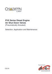
1.5 NAMEPLATE INFORMATION<br />
The nameplate located on the turbine housing provides<br />
important information regarding the construction of your<br />
<strong>T50</strong>-P air starter, refer to Figure 1. The part number<br />
coding explanation, refer to Figure 2, can help you<br />
when talking to your distributor.<br />
NOTE<br />
You should always have the starter’s Part Number,<br />
Serial Number, Operating Pressure, and Direction of<br />
Rotation information before calling your TDI distributor<br />
or dealer.<br />
TURBOTWIN<br />
PNUEMATIC STARTER<br />
TECH DEVELOPMENT INC.<br />
6800 POE AVE.,DAYTON<br />
OH<br />
MODEL NO. SERIAL NO. CW(RH) (CCW)LH)<br />
T510 9910-112 X .<br />
PART NUMBER<br />
T510-60048-01R-4 .<br />
HOUSING PROOF PRESSURE IS 600 PSIG<br />
MAX OPERATING INLET PRESS. 120 PSIG<br />
WARNING DO NOT OPERATE UNLOADED, WITHOUT EXHAST<br />
GUARD OR WITHOUT EXHAUST FITTING<br />
Figure 1. TDI TURBOTWIN Nameplate<br />
MODEL <strong>T50</strong> PRODUCT<br />
T5 10 - 60048 - 01R - 0 - 00<br />
NUMBER OF NOZZLES<br />
00= 0 DEGREES (STD)<br />
08= 8 NOZZLES<br />
01= 30 DEGREES<br />
10= 10 NOZZLES<br />
02= 60 DEGREES<br />
14= 14 NOZZLES<br />
03= 90 DEGREES<br />
04= 120 DEGREES<br />
05= 150 DEGREES<br />
DRAWING NUMBER FOR <strong>T50</strong> MODEL TYPE<br />
06= 180 DEGREES<br />
60048= <strong>T50</strong>P (PRE-ENGAGED, OUTBOARD NOSE, 11.2:1 RATIO, SAE 3 MOUNT)<br />
60051= <strong>T50</strong>Y (PRE-ENGAGED, OVERHUNG PINION, 11.2:1 RATIO, SAE 3 MOUNT)<br />
60052= <strong>T50</strong>Y (PRE-ENGAGED, OVERHUNG PINION, 11.2:1 RATIO, SAE 1 MOUNT)<br />
EXHAUST OPTIONS<br />
0= EXHAUST SCREEN<br />
PINION CODES<br />
1= (NOT AVAILABLE)<br />
2= 2" NPT STRAIGHT<br />
01= 6/8 DP, 11T ON 12T BLANK, 2.00 PD, 20° PA<br />
3= (NOT AVAILABLE)<br />
02= 8/10 DP, 12T ON 13T BLANK, 1.625 PD, 20° PA<br />
03= 8/10P, 10T ON 11T BLANK, 1.375 PD, 20° PA<br />
4= EXHAUST CLOSURE PLATE (ECP)<br />
04= 3 MOD, 9T ON 9.567T BLANK, 1.063 PD, 14.5° PA<br />
5= (NOT AVAILABLE)<br />
05= 3 MOD, 11T ON 11.7 BLANK, 1.299 PD, 14.5° PA<br />
6= (NOT AVAILABLE)<br />
06= 3.5 MOD, 11T ON 11.64T BLANK, 1.516 PD, 14.5° PA<br />
7= (NOT AVAILABLE)<br />
07= 3.5 MOD, 13T ON 13.7T BLANK, 1.791 PD, 14.5° PA<br />
8= (NOT AVAILABLE)<br />
08= 8/10P, 13T ON 14T BLANK, 1.750 PD, 20° PA<br />
09= 3.5 MOD, 15T ON 15.66T BLANK, 1.772 PD, 14.5° PA<br />
ROTATION<br />
10= USE CODE #03 (THIS IS A LH VERSION)<br />
R= RH (CW)<br />
11= 3.5 MOD, 17T ON 17.67T BLANK, 2.343 PD, 14.5° PA<br />
L= LH (CCW)<br />
12= USE CODE #02 (THIS IS A LH VERSION)<br />
13= 3.5 MOD, 14T ON 14.7T BLANK, 1.929 PD, 14.5° PA<br />
14= 8/10DP, 12T ON 12T BLANK, 1.500 PD, 20° PA<br />
15= 4.25 MOD, 11T ON 11T BLANK, 1.840 PD, 20° PA<br />
16= 6/8DP, 12T ON 12.7T BLANK, 2.126 PD, 20° PA<br />
17= USE CODE #01 (THIS IS A LH VERSION)<br />
18= USE CODE #07 (THIS IS A LH VERSION)<br />
19= 8/10 DP, 12T ON 13T BLANK, 1.625 PD, 20° PA<br />
20= 3.5 MOD, 14T ON 14.7T BLANK, 2.026 PD, 20° PA<br />
21= 4 MOD, 15T ON 15.65T BLANK, 2.465 PD, 0.325 CORRECTION FACTOR, 14.5° PA<br />
22= 3.5 MOD, 14T ON 14.68T BLANK, 2.023 PD, 0.34 CORRECTION FACTOR, 14.5° PA<br />
23= 3.5 MOD, 14T, 2.023 PD, 0.34 CORRECTION FACTOR, 20° PA<br />
Figure 2. <strong>T50</strong> Series Nameplate Identification<br />
ORIENTATION OF INLET/CONTROL PORTS<br />
07= 210 DEGREES<br />
08= 240 DEGREES<br />
09= 270 DEGREES<br />
10= 300 DEGREES<br />
11= 330 DEGREES<br />
Page 2<br />
Publication T5-703, Rev. 2<br />
Issued: July 31, 2009
TDI TURBOTWIN<br />
FROM TECH DEVELOPMENT<br />
SECTION 2.0 DESCRIPTION OF<br />
BASIC GROUPS<br />
2.1 GENERAL<br />
The TDI Turbotwin <strong>T50</strong>-P air starter is a lightweight,<br />
compact unit driven by a two stage turbine air motor.<br />
The starter is composed of three basic assembly<br />
groups: Turbine Housing Assembly, Gearbox Housing<br />
Assembly, and Bendix Drive Assembly.<br />
2.2 TURBINE HOUSING ASSEMBLY<br />
The Turbine housing assembly, refer to figure 3,<br />
consists of a stage one (23) and a stage two (13)<br />
turbine rotor mounted on sungear shaft (29). The front<br />
bearing (15) is secured by a retainer plate (27) and the<br />
aft bearing is pre-load by a spring washer (16).<br />
The ring gear (31) is installed between the turbine<br />
assembly (26) and the gearbox housing (41) and<br />
secured by four screws (42).<br />
Figure 3. Turbine Housing Assembly<br />
Publication: T5-703, Rev. 2 Page 3<br />
Issued: July 31, 2009
TDI TURBOTWIN<br />
FROM TECH DEVELOPMENT<br />
2.3 GEARBOX HOUSING ASSEMBLY<br />
The gearbox housing assembly, refer to figure 4,<br />
consists of a planet gear carrier and output shaft (32),<br />
three planet gears (36), needle bearings (37), spacers<br />
(35), and planet shafts (34).<br />
The carrier shaft (32) is mounted on a single bearing<br />
(38) in the gearbox housing (41). The retainer ring (48)<br />
secures the carrier shaft in the gearbox housing. The<br />
bearing housing (44) and pre-engaged piston (50) are<br />
installed in the gearbox housing (31).<br />
Figure 4. Gearbox Housing Assembly<br />
2.4 DRIVE ASSEMBLY<br />
The drive assembly, refer to figure 5, consists of a preengagement<br />
drive (53) and drive housing (56). Twelve<br />
screws (57) secure the drive housing to the gearbox<br />
housing.<br />
The front end of the carrier shaft (32) is mounted in a<br />
needle bearing (58), which is installed in the nose of<br />
the drive housing.<br />
Split rings (52) and a return spring (54) aid in the<br />
disengagement of the pinion from the engine’s ring<br />
gear.<br />
Figure 5. Drive Assembly<br />
Page 4<br />
Publication T5-703, Rev. 2<br />
Issued: July 31, 2009
TDI TURBOTWIN<br />
FROM TECH DEVELOPMENT<br />
SECTION 3.0 DISASSEMBLY<br />
3.1 GENERAL<br />
Always mark adjacent parts on the starter; Nozzle 2/<br />
Containment Ring (21), Turbine Housing (26), Gearbox<br />
Housing (41), and Drive Housing (56) so these parts<br />
can be located in the same relative position when the<br />
starter is reassembled.<br />
Do not disassemble the starter any further than<br />
necessary to replace a worn or damaged part<br />
Always have a complete overhaul kit on hand before<br />
starting any overall of a Turbotwin <strong>T50</strong>-Pair starter.<br />
Never use old screws, seals, and o-rings.<br />
The tools listed in Table 1 are suggested for use by<br />
technicians servicing the Turbotwin <strong>T50</strong>-P air starter.<br />
The best results can be expected when these tools are<br />
used.<br />
TOOL DESCRIPTION<br />
TDI/PN<br />
Spanner Wrench 2-27272<br />
Stage 2 Rotor Puller Tool 52-20076<br />
Tool, Turbine Bearing 45-25294<br />
Tool, Bearing/Seal 2-26943<br />
Tool, Seal Positioning 45-25316<br />
Table 1. <strong>T50</strong> Series <strong>Service</strong> Tools (P/N: <strong>T50</strong>-28570)<br />
3.2 DRIVE HOUSING<br />
3.2.1 Removal of Drive Housing<br />
3.3 GEARBOX HOUSING<br />
3.3.1 Removal of Gearbox Housing<br />
Remove the four screws (42) and separate the gearbox<br />
assembly from the turbine assembly. If the gearbox is<br />
too tight, tap it with a mallet to loosen.<br />
3.3.2 Gearbox Disassembly<br />
Remove snap ring (48) and two thrust washers (47)<br />
from carrier shaft (32).<br />
Apply pressure to the carrier shaft to remove it from the<br />
gearbox housing.<br />
Remove four screws (39) and press the bearing<br />
housing/pre-engaged piston assembly (44,50) from the<br />
gearbox housing.<br />
Hand press bearing housing (44) out of pre-engaged<br />
piston (50).<br />
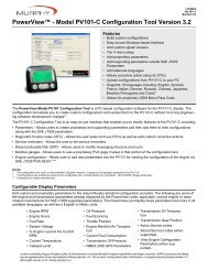
3.3.3 Carrier Shaft/Planet Gear Disassembly<br />
Remove snap ring (33) from planet shaft (34) and push<br />
shaft through holes in assembly. Refer to figure 6.<br />
Slide the planet gear (36) out from the carrier shaft and<br />
remove the two spacers (35).<br />
Press the needle bearing (37) from the planet gear (36)<br />
to remove it.<br />
Mark position of drive pinion opening relative to<br />
gearbox housing for reference during re-assembly.<br />
Remove the 12 screws (57) and pull drive housing (56)<br />
from gearbox housing (41). If drive housing is too tight,<br />
tap it with a mallet to loosen.<br />
3.2.2 Removal of Drive<br />
Remove return spring (54) and pull drive (53) from<br />
carrier shaft assembly (32).<br />
PLANET<br />
GEAR (36)<br />
CARRIER SHAFT<br />
ASSEMBLY (32)<br />
PLANET GEAR<br />
SPACER (35)<br />
Remove split rings (52) from drive assembly.<br />
3.2.3 Drive Bearing Removal<br />
Press needle bearing (58) from drive housing (56)<br />
using press tool.<br />
PLANET<br />
BEARING (37)<br />
PLANET<br />
SHAFT (34)<br />
RETAINING<br />
RING (33)<br />
Figure 6. Carrier Shaft Disassembly<br />
Publication T5-703, Rev. 2 Page 5<br />
Issued: July 31, 2009
TDI TURBOTWIN<br />
FROM TECH DEVELOPMENT<br />
3.4 TURBINE HOUSING<br />
3.4.1 Stage 2 Rotor Removal<br />
Remove four screws (4), ECP assembly (5), exhaust<br />
support (9), and exhaust guard (10). Units with an<br />
exhaust screen (no ECP) will utilize 8 screws.<br />
Hold the stage 2 rotor (13) and remove the turbine<br />
screw (11) and washer (12).<br />
NOTE<br />
Secure the sun gear (29) in a soft jaw vise when<br />
removing turbine screw.<br />
Install rotor puller tool P/N 52-20076 and remove the<br />
stage 2 rotor as shown in figure 7.<br />
Remove the aft bearing (15), wavy washers (16), and<br />
labyrinth (17) from nozzle 2.<br />
Install three screws (42) removed from the gearbox<br />
housing into the jack holes on the turbine housing (26)<br />
as shown in figure 9.<br />
Turn the screws in sequence until the turbine housing<br />
(26) is completely removed from the nozzle 2 (21).<br />
Remove the stage 1 rotor (23) and square key (14).<br />
Press turbine shaft (29) through forward bearing (15) to<br />
remove bearing from shaft.<br />
ROTOR, STG 1 (23)<br />
PRESSING TOOL<br />
ARBOR<br />
PRESS<br />
PULLER TOOL<br />
52-20076<br />
SQUARE KEY (14)<br />
ROTOR 2<br />
(13)<br />
TURBINE SHAFT (29)<br />
NOZZLE, STAGE 1 (26)<br />
NOZZLE 2/CONTAINMENT<br />
RING (21)<br />
Figure 8. Turbine Shaft Removal<br />
NOZZLE, STAGE 1 (26)<br />
1/4 - 20 UNC SCREW<br />
Figure 7. Turbine Rotor Removal<br />
Remove the square key (14)) from turbine shaft (29).<br />
3.4.2 Turbine Housing Disassembly<br />
Place the turbine on a firm surface with the sun gear<br />
end facing up.<br />
Remove three screws (28) and bearing retainer plate<br />
(27) from turbine housing (26). Units with S/N: 0610-<br />
0994 and after will utilize four screws.<br />
With the exhaust end facing up, press turbine shaft (29)<br />
through turbine housing (26) as shown in figure 8.<br />
Remove labyrinth (24) from turbine shaft.<br />
Page 6<br />
NOZZLE 2/CONTAINMENT<br />
RING (21)<br />
Figure 9. Nozzle 2 Removal<br />
Publication T5-703, Rev. 2<br />
Issued: July 31, 2009
TDI TURBOTWIN<br />
FROM TECH DEVELOPMENT<br />
SECTION 4.0 CLEANING and<br />
INSPECTION<br />
4.1 CLEANING<br />
Degrease all metal parts, except bearings, using a<br />
commercially approved solvent. Refer to Table 2.<br />
NOTE<br />
Never wash bendix assembly or bearings in cleaning<br />
solvents. It is recommended bearings be replaced<br />
with new parts.<br />
Clean aluminum parts using the solutions per Table 2;<br />
soak for 5 minutes. Remove parts, rinse in hot water,<br />
and dry thoroughly.<br />
Clean corroded steel parts with a commercially<br />
approved stripper.<br />
Clean corroded aluminum parts by cleaning as stated<br />
above and then immerse the parts in chromic-nitricphosphoric<br />
acid pickle solution per Table 2. Rinse in<br />
hot water and dry thoroughly.<br />
MATERIAL or COMPOUND<br />
MANUFACTURER<br />
Degreasing Solvent (Trichloroethylene) (O-T-634) Commercially Available<br />
Acetone<br />
Commercially Available<br />
Aluminum Cleaning Solution Diversey Corp., 212 W. Monroe, Chicago, IL 60606<br />
Dissolve 5 oz of Diversey 808 per gallon of water at<br />
155- 165F.<br />
Steel Cleaner - Rust & Corrosion<br />
Oakite Products Corp., 50 Valley Rd., Berkeley<br />
Heights, NJ 07992<br />
Mix 3-5 lb. of Oakite rust Stripper per gallon of water;<br />
use at 160- 180F.<br />
Chromic-Nitric-Phosphoric Acid Pickle Solution<br />
Mix 8lb. of chromic acid, 1.9 gal. of phosphoric acid,<br />
1.5 gal. of nitric acid with enough water to make a<br />
total of 10 gal. of solution.<br />
WARNING Follow all instructions provided with the MSDS sheets on the materials and compounds listed<br />
above.<br />
Table 2. Cleaning Materials and Compounds<br />
4.2 INSPECTION<br />
Use Table 3 as a guide to check for acceptable<br />
condition of the parts listed.<br />
Check all threaded parts for galled, crossed stripped, or<br />
broken threads.<br />
Check all parts for cracks, corrosion, distortion, scoring,<br />
or general damage.<br />
Check all bearing bores for wear.<br />
Check gear teeth and turbine housing ring gear for<br />
wear. In general, visually check for spalling, fretting,<br />
surface flaking, chipping, splitting, and corrosion. If<br />
wear is apparent, check the gear teeth dimensions in<br />
accordance with Table 4. Nicks and dents that cannot<br />
be felt with a .020 inch radius scribe are acceptable.<br />
Publication T5-703, Rev. 2 Page 7<br />
Issued: July 31, 2009
TDI TURBOTWIN<br />
FROM TECH DEVELOPMENT<br />
Part<br />
Description<br />
Check For<br />
Requirements<br />
(Defective Parts Must Be Replaced)<br />
Drive Worn loose or missing parts Defective unit to be replaced. Use figure<br />
10 as a guideline for acceptable pinion<br />
wear.<br />
Drive Housing Cracks and breakage Cracks are not acceptable<br />
Planet Gear Cracked, chipped, worn, or<br />
galled teeth.<br />
Wear must not exceed limits per table 4.<br />
There shall be no evidence of excessive<br />
Carrier Shaft Cracks, scoring or raised<br />
metal in planet shaft holes<br />
and keyways. Integrity of<br />
knurl/keyed connection.<br />
wear.<br />
Deformation of metal (smearing) in planet<br />
pin holes & keyways not acceptable.<br />
Scoring on bearing diameter not to<br />
exceed .005 depth.<br />
Wear must not exceed limits per Table 4.<br />
Planet Pins Wear grooves or flat spots Wear grooves in flat spots not permitted.<br />
Wear must not exceed limits per Table 4.<br />
Washers Wear grooves Wear must not exceed limits per Table 4.<br />
Gearbox Housing Cracks and Breakage Cracks and breakage not acceptable.<br />
Sungear/Turbine<br />
Shaft<br />
Cracks, scoring, wear<br />
grooves, chipped or broken<br />
gear- teeth, galling or scoring<br />
on bearing surface of shaft.<br />
Raised metal on the keyway. Wear must not exceed limits per Table 4.<br />
Spacers Parallelism of end surfaces Ends must be parallel within 0.0005.<br />
Turbine Housing Cracks and breakage Cracks and breakage are not acceptable.<br />
Minor surface damage is permitted if<br />
function is not impaired.<br />
Ring Gear Cracks, worn, chipped, or Wear must not exceed limits per Table 4.<br />
broken gear teeth.<br />
Needle Bearings Freedom of needle rollers Replace bearings<br />
Ball bearings Freedom of rotation without Replace bearings<br />
excessive play between races<br />
Containment Corrosion, erosion, cracks Cracks and breakage are not acceptable.<br />
Ring/ Nozzle and broken nozzle edges. Minor surface damage is permitted if<br />
Turbine Rotors Corrosion, erosion, cracks<br />
and broken edges.<br />
function is not impaired.<br />
Minor tip rub is permitted if function is not<br />
impaired.<br />
Bore and key way wear Wear is not permitted.<br />
Table 3. Parts Inspection Check Requirements<br />
Page 8<br />
Publication T5-703, Rev. 2<br />
Issued: July 31, 2009
TDI TURBOTWIN<br />
FROM TECH DEVELOPMENT<br />
PART DESCRIPTION LIMIT, <strong>Inc</strong>hes<br />
Ring gear / Turbine Housing<br />
Internal measurement<br />
between two .072 diameter 4.6655 max.<br />
pins.<br />
Sun Gear / Turbine Shaft<br />
Bearing diameter<br />
External measurement over<br />
two .072 diameter pins.<br />
11.2:1 .5566 min<br />
Planet Gear<br />
External measurement over<br />
two .085 diameter pins.<br />
11.2:1 2.2217 min<br />
Table 4. Parts Wear Limits<br />
Figure 10. Gear Teeth Wear Allowances<br />
ITEM NUMBER *<br />
TORQUE<br />
In-lbs Nm<br />
4 (Screw) 190 21<br />
11 (Screw) 220 25<br />
18 (Screw) 75 8<br />
28 (Screw) 113 13<br />
39 (Screw) 81 9<br />
42 (Screw) 190 21<br />
57 (Screw) 190 21<br />
* Refer to section 6 for part number<br />
identification.<br />
Table 5. Torque Values<br />
Publication T5-703, Rev. 2 Page 9<br />
Issued: July 31, 2009
TDI TURBOTWIN<br />
FROM TECH DEVELOPMENT<br />
SECTION 5.0 ASSEMBLY<br />
5.1 GENERAL INFORMATION<br />
ARBOR<br />
PRESS<br />
The tools listed in Table 1 are suggested for use by<br />
technicians servicing the Turbotwin <strong>T50</strong>-P air starter.<br />
The best results can be expected when these tools are<br />
used.<br />
PRESSING<br />
TOOL 2-26943<br />
CAUTION<br />
Replace all screws, o-rings, lip seals, and bearings.<br />
These parts are included in the overhaul kit shown in<br />
the Parts List, Section 6.0.<br />
NOTE<br />
Always press the inner race of a ball bearing when<br />
installing a bearing onto a shaft. Always press the<br />
outer race of a ball bearing when installing into a<br />
housing. DO NOT LOAD BEARING BALLS.<br />
Lubricate all o-rings with petroleum jelly or Parker O-<br />
ring Lube before assembly. Refer to Table 5 for a list<br />
of materials to be used during assembly.<br />
MATERIALS<br />
SOURCE<br />
Petroleum Jelly Commercially Available<br />
Parker-O-Ring Lube Commercially Available<br />
Aeroshell #6 Grease Commercially Available<br />
Loctite RC290 Commercially Available<br />
Grease, gearbox TDI P/N 9-94121-001<br />
Table 6. Materials for Assembly<br />
5.2 TURBINE HOUSING<br />
5.2.1 TURBINE BEARING INSTALLATION<br />
Press the turbine bearing (15) onto the turbine shaft<br />
(29) until seated.<br />
Press the turbine bearing/shaft assembly (15,29) into<br />
the turbine housing (26). Use press tool P/N 2-26943 if<br />
required per figure 11. Do not press on the end of the<br />
shaft because the load could damage the bearing balls.<br />
Install the bearing retainer (27) into the turbine housing<br />
(26) and secure with three screws (28) Torque to 75<br />
in-lbs. Units with S/N: 0610-0994 and after will utilize<br />
four screws.<br />
Install o-ring (25) onto turbine housing (20).<br />
Figure 11. Turbine Bearing / Shaft Installation<br />
5.2.2 ROTOR 1 INSTALLATION<br />
Turn the turbine nozzle over (exhaust end up) and<br />
install the labyrinth (18) onto the shaft. For units with<br />
0610-0994 and after press lip seal P/N: 2-26179 onto<br />
spacer P/N: 9-93114 and press lip seal with lips facing<br />
up into aft end of nozzle 1.<br />
Press the square key (14) into the keyway of turbine<br />
shaft (29) until seated.<br />
Install stage 1 rotor (23) by sliding over turbine shaft<br />
(29), while simultaneously aligning the key with the<br />
keyway in the rotor.<br />
5.2.3 STAGE 2 NOZLE INSTALLATION<br />
Install turbine housing (26) into nozzle 2 containment<br />
housing (21).<br />
NOTE<br />
The air inlet port on nozzle 2 must be aligned with the<br />
casting indentation on the turbine housing.<br />
5.2.4 ROTOR 2 INSTALLATION<br />
Turn the turbine nozzle over (exhaust end up) and<br />
install the labyrinth (17) onto the shaft.<br />
Install pre-load springs (16) into bearing bore of nozzle<br />
2 containment housing (21).<br />
Page 10<br />
Publication T5-703, Rev. 2<br />
Issued: July 31, 2009
Apply a light coating of oil to the bearing bore in the<br />
Nozzle Containment Assembly and press the turbine<br />
bearing (15) over the turbine shaft and into the bearing<br />
bore using press tool P/N. 2-26943<br />
Insert key (14) into turbine shaft keyway and install<br />
stage 2 rotor (13) onto shaft while simultaneously<br />
aligning the key with the keyway in the rotor.<br />
Secure stage 2 rotor with rotor washer (12) and rotor<br />
screw (11). Torque to 220 in-lb.<br />
Turn turbine housing over and install o-ring (30) into<br />
the o-ring groove on the turbine housing (26).<br />
Install plug (22) into Nozzle Containment Assembly.<br />
Install the ring gear (31) onto turbine housing with the<br />
dowel pin hole facing up.<br />
Install dowel pin (40) into dowel pin hole in ring rear<br />
(31).<br />
5.3 GEAR BOX ASSEMBLY<br />
5.3.1 PLANETARY GEAR CARRIER ASSEMBLY<br />
Press needle bearings (37) into planet gears (36) using<br />
arbor press. The bearing ID stamping must be against<br />
pressing tool. The bearing should be centered<br />
between gear faces.<br />
Place thrust washer (35) on each side of planet gear<br />
(36) and install into carrier shaft (32) slot.<br />
Install planet shaft (34) into the carrier and secure with<br />
snap ring (33). Be sure the anti-rotation pin is inserted<br />
into the slot on the carrier shaft.<br />
5.3.2 CARRIER SHAFT INSTALLATION<br />
Install o-ring (43) into forward side of gearbox housing<br />
(41).<br />
If removed, press gearbox bushing (38) into bearing<br />
housing (44).<br />
Press the lip seal (46) into the forward side of the<br />
bearing housing (44) until seated using press tool P/N:<br />
2-26943.<br />
TDI TURBOTWIN<br />
FROM TECH DEVELOPMENT<br />
Install o-ring (43) into the groove on the bearing<br />
housing (44).<br />
NOTE<br />
Apply a small amount of Aeroshell grease to the outer<br />
wall of the bearing hub and the inside wall of the<br />
gearbox housing to allow for easier housing installation.<br />
Install the bearing housing assembly (38,44,46) in the<br />
forward side of the gearbox housing (41) and secure<br />
with four screws (39). Torque to 81 In-Lbs.<br />
Install two o-rings (49,51) into the grooves on the preengaged<br />
piston (50).<br />
NOTE<br />
Apply a small amount of Aeroshell # 6 grease to the<br />
inner and inner walls of the pre-engaged piston to allow<br />
for easier installation.<br />
Press pre-engaged piston into the forward side of the<br />
gearbox housing and remove any excess grease from<br />
gearbox housing.<br />
Install lip seal tool PN: 45-25316 into forward side of<br />
gearbox housing (41) placing tapered end of tool into<br />
lip seal (46).<br />
Install gearbox housing onto carrier shaft and place two<br />
thrust washers (47) on carrier shaft (32). Secure with<br />
snap ring (48) using snap ring pliers.<br />
5.3.3 DRIVE INSTALLATION<br />
Apply a small amount of Aeroshell # 6 grease to split<br />
rings (52) and install split rings onto drive assembly<br />
(53).<br />
Install o-ring (55) onto drive housing (56)<br />
Install the drive assembly (53) onto carrier shaft and<br />
place return spring (54) over drive assembly.<br />
5.3.4 NOSE BEARING INSTALLATION<br />
Place the drive housing onto arbor press with the nose<br />
of drive facing down.<br />
Press needle bearing (58) into drive housing (56) using<br />
arbor press. The bearing ID stamping must be against<br />
pressing tool. Do not press bearing tight against the<br />
Publication T5-703, Rev. 2 Page 11<br />
Issued: July 31, 2009
drive housing shoulder. In addition, be sure stamped<br />
end is beneath shoulder of bearing bore.<br />
5.4 FINAL ASSEMBLY<br />
Apply o-ring grease to o-ring (30) and install onto<br />
gearbox housing.<br />
Apply liberal amounts of grease (100 grams) to planet<br />
gears (36), turbine shaft sun gear (29) and ring gear<br />
(31).<br />
TDI TURBOTWIN<br />
FROM TECH DEVELOPMENT<br />
Align gearbox assembly with turbine assembly and<br />
fasten together with four screws (42).<br />
Install drive housing (56) onto gearbox housing (41)<br />
and secure with twelve screws (57). Torque to 150 inlb.<br />
Install exhaust closure plate assembly using four<br />
screws (4). Torque to 150 in-lb.<br />
Temporarily install one screw (42) into ring gear (31) to<br />
prevent it from rotating while applying grease.<br />
Page 12<br />
Publication T5-703, Rev. 2<br />
Issued: July 31, 2009
TDI TURBOTWIN<br />
FROM TECH DEVELOPMENT<br />
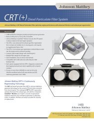
SECTION 6.0 PARTS LIST<br />
The components illustrated and/or described in this section are for the Turbotwin <strong>T50</strong>-P air starter. When rebuilding<br />
a <strong>T50</strong>-P air starter, it is recommended to purchase and completely install the appropriate service kit(s).<br />
<strong>T50</strong>-P ILLUSTRATED PARTS LIST<br />
Overhaul Kit<br />
ITEM # DESCRIPTION PART NUMBER QTY. <strong>T50</strong>P-28533-001<br />
1 Nut, Hex 9-92155-06 1 <br />
2 Washer, Flat 9-93018-011 2<br />
3 Plate, Baffle 2-20192 1<br />
4 Screw 14F-25020-014 8 <br />
5 Housing, Exhaust Cover 2-28369 1<br />
6 Bushing 9-91436 1<br />
7 Spring, Compression 9-90408-016 1<br />
8 Post 2-27223 1<br />
9 Exhaust Support 2-27475 1<br />
10 Exhaust Guard 2-28380 1<br />
11 Screw, Rotor Attachment 14F-25028-012 1 <br />
12 Rotor Washer 9-93047 1<br />
13 Stage 2 Rotor 2-28410 1<br />
14 Square Key (1/8") 9-90220-050 2 <br />
15 Turbine Bearing 9-91224 2 <br />
16 Bearing Pre-Load Spring 9-90439 2 <br />
17 Spacer / Labyrinth 2-28445 1 <br />
18 Screw 71F-31218-020 4<br />
19 Inlet Flange 2-28360 1<br />
20 O-Ring 9-90001-031 1 <br />
21 Containment, Nozzle 2, RH 2-28359-00R 1<br />
21 Containment, Nozzle 2, LH 2-28359-00L 1<br />
22 Hollow Hex Plug 9-93501-002 1<br />
23 Stage 1 Rotor 2-27225 1<br />
24 Spacer/Labyrinth 2-28444 1 <br />
25 O-Ring 9-90001-047 1 <br />
26 Turbine Hsg. / Stage 1 (10 Noz. RH) 2-28354-10R 1<br />
26 Turbine Hsg. / Stage 1 (10 Noz. LH) 2-28354-10L 1<br />
26 Turbine Hsg. / Stage 1 (14 Noz. RH) 2-28354-14R 1<br />
26 Turbine Hsg. / Stage 1 (14 Noz. LH) 2-28354-14L 1<br />
27 Bearing Retainer 2-28446 1<br />
28 Screw 71F-25020-012 3 <br />
29 Turbine Shaft 11.2:1) 2-28339 1<br />
30 O-Ring 9-90001-047 2 <br />
Publication T5-703, Rev. 2 Page 13<br />
Issued: July 31, 2009
TDI TURBOTWIN<br />
FROM TECH DEVELOPMENT<br />
Overhaul Kit<br />
ITEM # DESCRIPTION PART NUMBER QTY. <strong>T50</strong>P-28533-001<br />
31 Ring Gear 2-28430 1<br />
32 Carrier Shaft Assembly 2-28358 1<br />
33 Retaining Ring 9-92001-001 3<br />
34 Planet Shaft 2P-20182 3<br />
35 Planet Gear Spacer 9-93004 6 <br />
36 Planet Gear (11.2:1) 2-28316 3<br />
37 Planet Bearing 9-91004-001 3 <br />
38 Bushing 9-91405 1 <br />
39 Screw 14F-19024-012 4 <br />
40 Dowel Pin 9-91502-007-0-10 1<br />
41 Gearbox Housing 2-28352 1<br />
42 Screw 14F-25020-044 4 <br />
43 O-Ring 9-90001-035 1 <br />
44 Bearing Housing 2-24114 1<br />
45 O-Ring 9-90002-331 1 <br />
46 Lip Seal 2-23810 1 <br />
47 Thrust Washers 9-93085 2 <br />
48 Retaining Ring 9-92001-025 1 <br />
49 O-Ring 9-90002-336 1 <br />
50 Pre-engage Piston 2-24644-001 1<br />
51 O-Ring 9-90002-234 1 <br />
52 Split Rings 2-23419 2 <br />
53 Drive, 6/8P, 11T, RH 2-22954 1<br />
53 Drive, 6/8P, 11T, LH 2-22956 1<br />
53 Drive, 3.5MOD, 14T, RH 2-26816 1<br />
53 Drive, 3.5MOD, 14T, LH 2-25933 1<br />
53 Drive, 6/8P, 12T, RH 2-26143-001 1<br />
54 Return Spring 9-90422 1<br />
55 O-Ring 9-90001-041 1 <br />
56 Drive Housing (6/8P) 2-24127-007 1<br />
57 Screw 14F-25020-012 12 <br />
58 Nose Bearing (6/8P) 9-91408 1 <br />
Page 14<br />
Publication T5-703, Rev. 2<br />
Issued: July 31, 2009
TDI TURBOTWIN<br />
FROM TECH DEVELOPMENT<br />
Figure 12. <strong>T50</strong>-P Illustrated Parts List<br />
Publication T5-703, Rev. 2 Page 15<br />
Issued: July 31, 2009
TDI TURBOTWIN<br />
FROM TECH DEVELOPMENT<br />
<strong>T50</strong>-P TURBINE ASSEMBLY (effective serial #: 0610-0994)<br />
Overhaul Kit<br />
ITEM # DESCRIPTION PART NUMBER QTY <strong>T50</strong>P-28533-001<br />
24 Bearing Spacer 9-93114 1 √<br />
24A Lip Seal 2-26719 1 √<br />
26 Turbine Hsg. / Stage 1 (8 Noz. RH) 2-28354-08R 1<br />
26 Turbine Hsg. / Stage 1 (8 Noz. LH) 2-28354-08L 1<br />
26 Turbine Hsg. / Stage 1 (10 Noz. RH) 2-28354-10R 1<br />
26 Turbine Hsg. / Stage 1 (10 Noz. LH) 2-28354-10L 1<br />
26 Turbine Hsg. / Stage 1 (14 Noz. RH) 2-28354-14R 1<br />
26 Turbine Hsg. / Stage 1 (14 Noz. LH) 2-28354-14L 1<br />
27 Bearing Retainer 2-27406 1<br />
28 Screw 71F-25020-012 4 √<br />
Figure 13. Model <strong>T50</strong> Series Turbine Assembly Configured for Air & Natural Gas<br />
(Effective serial #: 0610-0994)<br />
Page 16<br />
Publication T5-703, Rev. 2<br />
Issued: July 31, 2009