


Create successful ePaper yourself
Turn your PDF publications into a flip-book with our unique Google optimized e-Paper software.
----..'/<br />
--------------------"'--...---------------<br />
·-..,··~-. ..~·.·.l~~r<br />
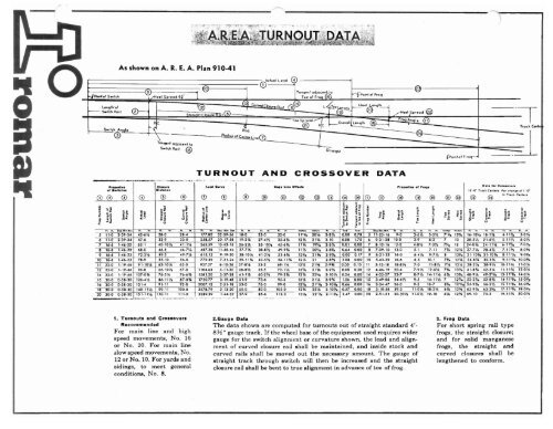
As shown on A. R. E. A. Plan 910-41<br />
I'<br />
~<br />
~~~~~~~~~~~~~~~~~~~~~~~~======i==c®C'.uO' Lead<br />
(Pol'" 0' Swlteh<br />
u"qlh'ol<br />
l----- S.,ieh Roll<br />
TCs)<br />
~ j Str~iahtCIOlurt F«;II (5).<br />
~., R~d<br />
1-1--==0 I \-<br />
S- >-<br />
, 11·0 2·39·3( '2.6V, 28·0 28·' 177.80 32·39·'6 18·0 2'·0 --32·0 11'1Ii ~2cf~ -0.00 0.78~.16 9·0 3·6VJ ,·,V, 7'1
(<br />
TURNOUTS<br />
Turnouts are the means by<br />
which rolling stock is<br />
diverted from one track to<br />
another. This is done by<br />
making use of a frog,<br />
switch, stock <strong>and</strong> closure<br />
rails. <strong>Romar</strong> maintains a<br />
working stock of turnout<br />
accessories in order to<br />
provide a complete turnout<br />
or to assist you in turnout<br />
or maintenance needs.<br />
.........rolllar_43<br />
-----1
DIAGRAMS giving names of the main formations in trackwork<br />
RIGHT HAND TURNOUT<br />
EQUILATERAL TURNOUT<br />
LEFT HAND TURNOUT<br />
THREE-WAY TURNOUT<br />
CROSSING<br />
FROG-TYPE CROSSING(<br />
RIGHT HAND CROSSOVER LEFT HAND CROSSOVER DOUBLE CROSSOVER<br />
o<br />
.....-rollla~_44 1
<strong>Rail</strong>road Frogs<br />
FROG CONSTRUCTION<br />
BOLTED RIGID FROGS - Constructed of carbon ste&! rails with<br />
rolled cast fillers, securely bolted together. While this type of<br />
construction may vary from heavy to extremely light duty, the<br />
rolled steel rails receive the full impact <strong>and</strong> wear.<br />
SPRING RAIL FROGS· Generally used on main lines where the<br />
turnout run is infrequently u~ed. Elim inating the open flangeway in<br />
the turnout run reduces impact <strong>and</strong> wear at the point, <strong>and</strong> provides<br />
smoother operation in the main line.<br />
RAIL BOUND MANGANESE STEEL FROGS· Designed for maximum<br />
severity of service, they incorporate acast managanese steel<br />
center, designed to receive the full impact <strong>and</strong> wear through the<br />
intersection. Rolled carbon steel rails support the manganese steel<br />
center, with arms extending to a point where conventional splices<br />
may !:'e able to the connecting rails. All components. lnell-ding<br />
fillers, are securely bolted with heat-treated bolts.<br />
SOLID MANGANESE STEEL FROGS· Completely integrated<br />
frogs. cast in one piece from manganese steel. Such a frog is<br />
designed to receive the connecting rails, so necessary straps <strong>and</strong><br />
special length bolts are furnished with the frog. The st<strong>and</strong>ard joint<br />
bars are usually supplied by the User.<br />
SOLID MANGANESE STEEL SELF-GUARDED FROGS - Similar<br />
to solid manganese steel frogs, with the addition of raised guards,<br />
cast integrally with the frog body. These are designed to guide the<br />
wheel flanges past the frog point. The design eliminates need for<br />
separate guard rails in the track opposite the frog <strong>and</strong> is used in<br />
yards <strong>and</strong> other locations where speeds are moderate to slow.<br />
FROG NUMBERS AND ANGLES ARE AS FOLLOWS<br />
No. 4 Frog - Angle 14°15'00"<br />
No. 5 Frog - Angle 11°25'16"<br />
No. 6 Frog - Angle 9°31'38"<br />
No. 7 Frog - Angle 8°10'16"<br />
No. 8 Frog - Angle 7°09'10"<br />
No. 9 Frog - Angle 6°21'35"<br />
No. 10 Frog - Angle 5°43'29"<br />
No. 11 Frog - Angle 5°12'18"<br />
No. 12 Frog - Angle 4°46'19"<br />
No. 14 Frog - Angle 4°05'27"<br />
No. 16 Frog - Angle 3°34'47"<br />
No. 18 Frog - Angle 3°10'56"<br />
No. 20 Frog - Angle 2°51'51"<br />
The simple turnout frog is a device to enable the wheels<br />
running on one track to cross the rail of a diverging track. It<br />
provides continuous channels for the wheel flanges, <strong>and</strong><br />
supports the wheels over the intersection of the flangeways.<br />
Turnout frogs are divided into two principal classes: RIGID<br />
FROGS, which are without movable parts; <strong>and</strong> SPRING RAIL<br />
FROGS, in which one wing is movable.<br />
Information required when ordering frogs<br />
Refer to type of frog required.<br />
<strong>Rail</strong> <strong>Section</strong>: weight, arid section number.<br />
Drilling for joints: distance from end of rail to center of first hole.<br />
DistanCe center to center, first <strong>and</strong> second holes, <strong>and</strong> second <strong>and</strong><br />
third holes. Diameter of holes. Distance from bottom of rail to center of hole.<br />
Frog angle or number.<br />
Length over all. Also distance from theoretical point to heel as<br />
indicated in diagram on following page.<br />
45<br />
rOIDar<br />
----I
FROG. DETAILS<br />
(<br />
Preferred names of parts<br />
When a frog is needed to meet certain existing conditions or a st<strong>and</strong>ard<br />
size cannot be used. it is necessary that certain dimensions be furnished<br />
before construction can take place.<br />
Send rough sketch showing LENGTH. TOE LENGTH. HEEL LENGTH.<br />
TOE SPREAD AND HEEL SPREAD. GIVE DIMENSIONS TO GAUGE.<br />
LINES AND FROM ACTUAL POINT OF FROG<br />
IMPORTANT: The above applies toSTRAIGHT FROGS ONLY. If ONE or<br />
BOTH tracks are curved. we will furnish special instructions.<br />
(<br />
HOW TO ORDER FROGS<br />
Give the following information:<br />
1. Type of Frog - refer to catalog figure number when same applies.<br />
2. Frog number or angle--found by dividing the length overall (L)<br />
by the sum of the gage line spreads at the heel <strong>and</strong> toe (HS & TS).<br />
3. Detail of <strong>Rail</strong>-weight <strong>and</strong> section number in rail manufacturer's<br />
catalog (See Page 112).<br />
Diagram to show how Frog Number is obtained<br />
for Curved Frog<br />
For curv~d (rog submit dio~ram showina: direction of curvature <strong>and</strong> radiu<br />
or sun;cien~ d:ata to c1etumine the curvature <strong>and</strong> radius. (Le.) the heet Iprca<br />
(HSl. toe spread (TS). h«1 offset (HOI <strong>and</strong> toe offset (TOl.<br />
GAGE<br />
LINE<br />
The Frog Number is the ratio of the SPREAQ 10 Its<br />
DISTANCE from the theoretical pOint The spread<br />
must be at right angles to the centerline. as shown In<br />
the diagram.<br />
For example: spread in the diagram IS 1" in 4". a ratio<br />
of 14. designating a Number 4 Frog If the spread to<br />
distance is 2" in 8". or 3" in 12" etc. the 14 ratio still<br />
holds. designating a Number 4 frog<br />
If spread to distance is '" in 7". or 2" in '4". the Frog<br />
Number is 7. Similarly. spread to distance of 3" in {<br />
15" designates a Number 5 frog 2" In 12". a Number<br />
6 frog: 2" in goo. a Number 4 1 /;>" frog. etc<br />
rolDar_46-------'
__- '"0G~lM6Tll HEEL. LEMGTH<br />
C<br />
L27 L27 L23<br />
SECTION A-A<br />
SECTION c-e<br />
SECTION B-B<br />
ELEVATION OF POINT<br />
BOLTED RIGID FR OG<br />
'/<br />
Recommended for yard And other medium speed<br />
turnouts where heavy duty design!; are not reqwred.<br />
St<strong>and</strong>ard lengths~Hnd the quantity
__..rOlllar_49-- ---1<br />
<strong>Rail</strong>bound Manganese<br />
STEEL FROGS A.R.E.A. Plans 622-625<br />
<strong>Rail</strong> bound manganese steel frogs for heavy traffic<br />
ELEVATION OF WING WHEEL RISER<br />
FROG AREA FROG FROG AREA FROG<br />
NO. PLAN LENGTH NO, PLAN LENGTH<br />
6 622 11'Or 12 624 20'4"<br />
7 622 12'0" 14 624 237"<br />
8 622 13'0" 15 624 24'4%"<br />
9 623 16'0" 16 625 26'0"<br />
10 623 16'6" 18 625 29'3"<br />
11 623 18'8'/2" 20 625 3O'10\fz"
~ook Twin Tie Plates<br />
,<br />
Required For <strong>Rail</strong>bound Manganese<br />
Steel Frogs<br />
Hook tWin lie plates as listed below will be furnished with frogs are classified by width - Type 1, Type 2, Type 3 - as indicatec<br />
unless. otherwIse specified. Quantities shown are based on in table. Any type, style or arrangement of plates can b<br />
19 1 //' lie spacing, with center of one tie 4" back of 112" point. <strong>Rail</strong>s furnished when specified.<br />
Hook twin tie plates required for A.R.E.A. frogs -<br />
Plans 611 to 615 inclusive.<br />
Type 1 <strong>Rail</strong>s - <strong>Rail</strong>s having Type 2 Ralls - <strong>Rail</strong>s having Type 3 <strong>Rail</strong>s - <strong>Rail</strong>s having<br />
base up 10 SJ/ 1fi " <strong>and</strong> head 2 9 / 16 " inc!. base up 10 5%" <strong>and</strong> head 2 3 / 4 " incl. base up 10 6" <strong>and</strong> head 3" incl.<br />
Frog Mark No. Mark No. Mark No.<br />
No. l23 l27 LR23 lR27 lR3l L23 L27 LR23 LR27 LR3l L23 L27 LR23 LR27 LR31<br />
4 4 4 2 0 0 2 6 2 2 0 2 6 2 2 0<br />
5 6 4 4 0 0 4 6 4 2 0 4 6 4 2 0<br />
--<br />
6 10 2 2 2 0 4 8 2 2 2 4 10 2 2 2<br />
7 12 4 2 2 0 8 8 2 2 2 10 6 2 2 2<br />
8 12 4 2 2 0 8 10 2 4 2 8 10 2 4 2<br />
9 16 4 2 2 0 10 .10 2 4 2 10 10 2 4 2<br />
10 16 4 4 2 0 12 8 4 4 2 12 10 4 4 2<br />
11 18 6 4 2 0 14 10 4 2 2 12 14 4 2 4<br />
12 18 8 4 4 0 14 12 4 4 2 12 14 4 4 4<br />
,14 22 8 4 4 0 16 14 4 6 2 14 16 4 6 4<br />
15 24 8 4 4 0 16 18 4 6 2 16 18 4 6 4<br />
16 26 8 6 2 0 16 18 6 6 2 16 20 6 6 4<br />
18 26 12 6 4 0 18 22 6 8 2 18 22 6 8 4<br />
20 32 10 6 6 0 20 24 6 8 4 16 28 6 8 6<br />
Hook twin tie plates required for A.R.E.A. frogs -<br />
Plans 622 to 625 inclusive.<br />
Type 2 <strong>Rail</strong>s - <strong>Rail</strong>s having base up 10 Type 3 <strong>Rail</strong>s - Ralls having base up 10<br />
5%" <strong>and</strong> head 2W' inct 6" <strong>and</strong> head 3" Inc!.<br />
Frog No. Mark No. Mark No.<br />
.<br />
L23 . l27 L3l LR23 LR27 LR31 L23 L27 L3l LR23 LR27 LR3l<br />
6 4 8 2 2 2 2 4 8 2 2 2 2<br />
7 4 10 2 2 2 2 4 10 2 2 2 2<br />
8 6 10 2 2 4 2 6 10 2 2 4 2<br />
9 e 10 2 ~ 4 ~ tl lU ~ 2 4 2<br />
10 10 10 2 2 4 2 10 12 2 2 4 2<br />
11 10 12 2 4 2 2 10 14 2 4 2 4<br />
12 10 14 2 4 4 2 10 14 2 4 4 4<br />
14 10 18 2 4 6 2 10 18 2 4 6 4<br />
15 12 18 4 4 6 2 12 18 4 4 6 4<br />
16 12 20 2 6 6 2 12 22 2 6 6 4<br />
18 16 22 2 6 8 2 16 22 2 6 8 4<br />
20 16 28 2 4 8 4 16 28 2 4 8 6<br />
J•<br />
.lQ<br />
- ...... ==- rolfta~ 51
Solid Manganese<br />
Steel Self-guarded Frogs<br />
Solid manganese steel self-guarded frogs can be used to<br />
eliminate cost of guard rail installation <strong>and</strong> maintenance<br />
in yard tracks <strong>and</strong> at terminals where speeds are<br />
moderate, <strong>and</strong> traffic is heavy.<br />
Frog is designed to guide the wheel flanges past the frog<br />
point by means of raised guards which form easy contact<br />
with the outside rim of the wheels, deflecting them into<br />
proper alignment without shock.<br />
A.R.E.A. has adopted st<strong>and</strong>ard plans for solid manganese<br />
steel self-guarded frogs of Nos. 4 to 10, inclusive.<br />
Solid manganese steel self-guarded frog. heavy duty type,<br />
desgined to provide years of dependable service under the most<br />
rugged conditions.<br />
Hook twin tie plates as listed below will be furnished with frogs<br />
unless otherwise specified. Quantities shown are based on<br />
19%" tie spacing, with center of onetie 4" back of l/2" point. <strong>Rail</strong>s<br />
are classified by width - Type 1, Type 2, Type 3 - as indicated<br />
in fable.<br />
QUANTITY OF HOOK TWIN TIE-PLATES REQUIRED<br />
Type 1 <strong>Rail</strong>s - <strong>Rail</strong>s having base up to Type 2 <strong>Rail</strong>s - <strong>Rail</strong>s having base up to Type 3 <strong>Rail</strong>. - <strong>Rail</strong>a having b.ae up 10<br />
53/,." <strong>and</strong> head 2'/11" incl. 5%" <strong>and</strong> head 23j.' incl. 6" <strong>and</strong> head 3" Incl.<br />
Mark No. Mark No. Mark No.<br />
Frog L L H H H H LR LR LR Frog L L H H H H LR LR LR Frog L L H H H H LA LR LA<br />
No. 23 27 23 27 31 35 23 27 31 No. 23 27 23 27 31 35 23 27 31 No. 23 27 23 27 31 35 23 27 31<br />
4 2 4 4 2 0 0 0 0 0 4 2 4 4 2 0 0 0 0 0 4 2 2 4 2 0 2 0 0 0<br />
5 4 2 4 2 0 2 0 2 0 5 4 2 4 2 0 2 0 2 0 5 4 2 4 2 0 2 0 2 0<br />
6 4 2 4 2 0 2 0 2 0 6 4 2 4 2 0 2 0 2 2 6 4 2 4 2 2 2 0 2 2<br />
7 4 4 2 4 0 2 2 2 0 7 4 4 2 4 0 2 2 2 2 7 4 2 4 4 2 2 0 2 2<br />
8 6 2 2 4 2 0 2 4 0 8 6 4 4 4 2 0 0 4 2 8 4 4 4 4 2 2 0 4 2<br />
9 8 2 2 4 2 0 2 4 0 9 6 4 4 6 0 0 2 4 2 9 4 4 6 6 2 0 0 4 2<br />
10 8 2 4 6 0 0 4 4 0 10 6 4 6 6 2 0 2 4 2 10 6 4 6 6 2 0 2 4 2<br />
I<br />
(<br />
rolftarS2<br />
I
L..---·----TOTAL LENGTH -----+,<br />
7 -IJZ* fOR ·9 FROG<br />
." fOR ·10 FROG<br />
fn I<br />
~j.,,~!<br />
TYPICAL PLAN VIEW<br />
FROG LENGTHS<br />
WHEElIISfl<br />
GROUP A RAilS GROUP B RAILS GROUP C RAilS GROUP D RAILS RAilS 112 lBS OR HEAVIER<br />
FIIOG DIIE/ISIONS FROG<br />
/10. NO.<br />
R' I' I' I' TotJl Toe Heel V.r. TotJl Toe H"I V'I, 10111 Toe H"I V.r. lot.l Toe lltel V.r. TotJl Toe Heel V.r.<br />
lel\lfh laneth l'ncth Radius l'ncth l·ncth l.nJlh ladius l.nelh lenJlh lenJlh Radius l.ncth lenclh ltnctlt Radius l'nclh lenclh l.nelh Radius<br />
4 11" 0" 2" 4" 5'1" 15" 3'10" 23" 5'1" IS" 3'10" 23" 5'1" IS" 3'10" 23" 5'1" IS" 3'10" n" 5'11" 2'1" 3'10" 23" 4<br />
I<br />
5 13'/, 0" 2V," 5" 5;6" 18" 4'0" 3'2" 5'5" 17" 4'0" 3'2" 5'5" 17" 4'0" 3'2" 5'5" ]7" 4'0" 3'2" 6'5" 2'1' 4'4" 3'3" 5<br />
6 16'h 0" 3" 6" 6'0" 22" 4'2" 4'10" 5'11" 21" 4'2" 4'10" 5'10" 20" 4'2" 4'9" 5'10" 20" 4'2" 4'9" 7'4" 2'11" 4'5" 5'0' 6<br />
7 18" n; 3Y," 7" 6'10" 2'1" 4'g" 6'9" 6'7" 2'0" 4'7" 6'8" 6'3" 23" 4'4" 6'8" 6'2" 22" 4'4" 6'6" 8'1'," 2'11" 5'2:," 7'1)" )<br />
8 18" 4" 4" 8" no" 2'5" 5'5" S'll" 1'7" 2'4" 5'3" S'IO" 7'3" 2'3" 5'0" S'g" 6'11" 2'l" 4'10" 8'7" 8'11" 2'11" 60" S-->" 8<br />
9 20'/. 4'h" 4Y," 9" 8'10" 2'9" 6'1" 11'5" 8'5" 2'7" 5'10" 11'3" 8'1" 2'6" 5'7" 11'2" 7'g" 2'4" 5'5" 11'0" g'g" 2'11" 6'10" 11'6" 9<br />
10 22V, 5" 5" 10" 9'9" 3'0" 6'9" 14'2" 9'4" 2'10" 6'6" 14'0" 8'11" 2'9" 6'2" 13'11" 8'7" 2'7" 6'0" 13'S" 11'4'," 3'9" 7'7'';' 14'S" 10<br />
-....-.....Olllar_ 3<br />
----..I
Hook Twin Tie Plates<br />
Hook Twin Tie Plates are easily installed<br />
rolled steel tie plates that fit any tie position under any frog<br />
regardless of length. angle or-rail weight. They may be used<br />
under frogs, crossing, guard rails, switch lead rails <strong>and</strong> other<br />
special track work.<br />
'~__L-~<br />
•:':P;lBe.;.,<br />
. ". "".~<br />
A pair of hook twin tie plates provides greater bearing surface<br />
than a single ordinary plate. Warping is minimized, while their<br />
greater holding power, both against thrust <strong>and</strong> lifting, helps<br />
maintain alignment.<br />
L<br />
1---- d<br />
'UIICH '" oJ.: IOLATU OIlLY<br />
L<br />
I I:<br />
Lit<br />
r ~<br />
fu o<br />
'"UTES<br />
, :<br />
iU<br />
~~--------::~--+-h'--!=;J.<br />
J."<br />
4 SO.<br />
I fso.'"I<br />
_ I"j if- l-·~,<br />
!::~::"5:1 \'<br />
I : : , : , ; : I<br />
"L" plates are used with rolled rail sections.<br />
"H" plates are used with manganese steel castings.<br />
PLATE MARK 1<br />
LENGTH<br />
THICKNESS<br />
I PLATE MARK I LENGTH ITHICKNESS<br />
]<br />
L23 23" 9/,6"<br />
L27 'l.7" ~16<br />
L31 31 16<br />
H23 23 16<br />
H27 27 16<br />
H31 31 16<br />
H~:> 35 16<br />
Hook Twin Tie Plates are manufactured according to<br />
A.R.E.A. st<strong>and</strong>ards on automatic equipment. <strong>and</strong> guaranteed against<br />
bending or breaking when properly installed,<br />
o<br />
rolfta r_4<br />
I
TWIN TIE PLATES<br />
FLAT PLATES: A.R.E.A. 241-41<br />
____2'.0 1 /," --;1<br />
31 ,,--:l-<br />
14 I<br />
i 3/0"<br />
01-<br />
Flat twin tie plates <strong>and</strong> hook twin tie plates provide<br />
more bearing area <strong>and</strong> better support for frogs <strong>and</strong><br />
switches. They prolong tie life <strong>and</strong> reduce maintenance<br />
<strong>and</strong> inventory costs; eliminate the need for storing many<br />
special-use plates that require specific punchings to<br />
adapt them for different rail sections <strong>and</strong> tie spacings.<br />
Twin tie plates are used "as is" for turnout plates, frog<br />
plates, switch plates <strong>and</strong> guard rail plates with all rail<br />
sections on any tie spacing. Two plates fit side by side<br />
on each tie, <strong>and</strong> easily adapt to any position.<br />
; i<br />
TYPE 2<br />
+-_-+-+__2_'.6'_'-_-_-_-_-_~~I-~--iaL>;."<br />
_ '2"! ! _ I<br />
3/0' I/."<br />
I 'rO T 4 .. ,<br />
~** >;." I~<br />
TYPE 3<br />
,<br />
3/. "<br />
~ I<br />
I<br />
LlJ<br />
,.<br />
t<br />
MAIN<br />
GUARD RAIL CLAMP<br />
This design for securing guard rails meets A.R.E.A.<br />
specifications <strong>and</strong> will withst<strong>and</strong> heaviest traffic. Yoke<br />
<strong>and</strong> wedge are made of heat treated forged steel. Yoke<br />
can be installed without removing guard rail, <strong>and</strong> ad·<br />
justments are quickly <strong>and</strong> easily made. Available for rail<br />
from 60 lb•. to 140 lbs. inclusive.<br />
o<br />
o<br />
o<br />
o<br />
1GU,"" .:" m "An<br />
GUARD RAil FLARE<br />
IS DOUBLE·PLANED<br />
A.R.E.A. 504-55<br />
Fixed flangewny type guard rail ends are double-planed.<br />
flared <strong>and</strong> beveled. St<strong>and</strong>ard ('quipment includes two<br />
heavy-duty end blocks <strong>and</strong> single separator block for<br />
8'-3" length. Two separator blocks are supplied with<br />
11' <strong>and</strong> 13' lengths. Shoulder tie plates are supplied 7"<br />
wide (or rail under 1121b <strong>and</strong> 8" wide (or rail over 1121b.<br />
F~=_}_~~-_=:-:~-::--=-.·:.--:.~.=.~:":=~'nd~·"·''':U'':-''~:~C';''''-G:':'~:':u-::'::::~:~S~~- --- ~;~~=~r<br />
This guard rail hos bent flores<br />
<strong>and</strong> Includes the feature of the aree guard roil.<br />
............OIft8r_ 55 ----1
"Otr41It.1l.tK,-:<br />
IWITCII DETAILS<br />
Diagrams, with names applying to various switch parts.<br />
No particular type or design is represented.<br />
!<br />
d:1<br />
~t<br />
~<br />
-:!/rOC"<br />
A'"<br />
-.!'WI (.M<br />
I(,'D RAIL MAtl<br />
)01.'0 &A~ ~1I0{ PI. An<br />
"f L<br />
rOOl.I(,IO ..... 8llACl<br />
PLAN VIEW (FOR ILLUSTRATION ONLY) INDICATING VARIOUS PARTS OF SWITCH LAYOUTS.<br />
DRAWN FOR LEFT HAND TURNOUT.<br />
1---------·---IlEKOAC... &A.~<br />
~---'e-CUT----- ._ p""" .Nl ••U<br />
ELEVATION OF SWITCH POINT WITH UNIFORM RISERS<br />
------·---·.. -··f'l(...,OIlC_a~- ~<br />
-----·-rCll'tuT--· _0 ... =.~L.~... I<br />
ELEVATION OF SWITCH POINT WITH GRADUATED RISERS<br />
NOMENCLATURE FOR ORDERING SWITCH<br />
A "Switch Complete" consists of the two switch points with<br />
necessary clips, bolls, rods. plates <strong>and</strong> braces. Reinforcing bars,<br />
stops, heel block assemblies, etc., are also included if the type of<br />
switch requires them.<br />
"Switch Points" mean~ the rails only, except for specified<br />
reinforcing bars, clips, stops <strong>and</strong> foot guards if required.<br />
NOTE: A "Switch" is not a "Turnout" ... only part of a "Turnout"<br />
To branch from a track requires a ''Turnout'', composed in the<br />
main of a "Frog" <strong>and</strong> a "Switch Complete" plus guard rails if<br />
required.<br />
rolllar_56<br />
_
-o<br />
I<br />
I<br />
I<br />
I<br />
I<br />
• .. .. .. 0 N N .. N N ..<br />
if<br />
.... .... .... .... .:Ii .:Ii<br />
"N .... e" ew e" .. ;;; .. ;;;<br />
.. ."."<br />
"N<br />
."." ."." ."." ."." ... ." ." ... ...." ."...<br />
...<br />
"..<br />
"<br />
St<strong>and</strong>ard Bill of Material<br />
For Industrial Switch<br />
-ii--<br />
Switch Switch<br />
Length<br />
How to Order Straight Switch<br />
1. Specify area plan number or Industrial switch If possible<br />
2. Roll NT. section <strong>and</strong> drilling<br />
3. Switch Length<br />
Rods<br />
11 '·0" I 2<br />
--<br />
15'·0" 2<br />
16'·6" 2<br />
Guage<br />
Plate<br />
1 Ea.<br />
1 Ea.<br />
1 Ea.<br />
Comb. Slid.<br />
Plate.<br />
&Braces<br />
Plain<br />
Slide<br />
Plat••<br />
10 2<br />
12 2<br />
14 2<br />
.,<br />
Heel<br />
Hee' Turnout<br />
Block Plates Plates<br />
... -<br />
1 Pr. 4 B<br />
-,,' ..' =<br />
1 Pr. 4 12<br />
4. Non-Insulated or Insulated<br />
5. Non reinforced. single or double reinforced<br />
6. Track guage<br />
7. Right or left h<strong>and</strong> switch If turnout Is curved<br />
_._. ---<br />
1 Pr. 4 12<br />
SWITCH HEEL BLOCK ASSEMBLY<br />
A<br />
'\._4 :"110..____ ---- .,<br />
Heel blocks are installed at heel of switch point to<br />
maintain the stock rail <strong>and</strong> heel of switch point in<br />
perfect alignment horizontally <strong>and</strong> vertically under<br />
heavy traffic conditions. Can be furnished in cast steel<br />
or in cast iron.<br />
When ortl~ring heel blocks or assemblies separately, it<br />
is necessary to specify if switch points are level with<br />
stock rail at heel ofswitch, <strong>and</strong> ifused with graduated<br />
or uniform risers. Also advise heel spread, length of<br />
point <strong>and</strong> switch desi~ number, rail weight <strong>and</strong> section,<br />
diameter, elevation <strong>and</strong> spacing of holes (G-H-G)<br />
injointbar. Ifnot ordered in palrs, specify iffor rightor<br />
left h<strong>and</strong> point. Can be furnished as bolted type (illustrated)<br />
or floating type.<br />
~ ti-L::,~,r,~<br />
H +<br />
CROSS<br />
SECTION A·A<br />
SECTION 8·8<br />
JOINT eAR HOLE SPACING<br />
~"olDar_57<br />
___
Transit Clip<br />
"'-l.....J......L--..., ,<br />
.!'===--a.-:::-=:C:::: : ........r-.;~_..:<br />
_<br />
_<br />
Switch clips connect the switch rod to the switch point.<br />
Switch clips are of single piece, rugged, cast steel design.<br />
••<br />
•<br />
Adjustable Side Jaw Clip<br />
Single Side Jaw Clip<br />
OCTAJlMQ<br />
JIOt .2012 3012<br />
.u. (l'''.<br />
OLTAll HQ<br />
AOJ SfDt 2112 3112<br />
"•• I;L.'<br />
.MM"''''''<br />
Ill• 1'11('<br />
B 2'/>.+ 3"<br />
Hie ttl 'f .....<br />
0;- 10\'1"· IY.f,°<br />
0 I'V~<br />
....<br />
RAIL$ 110 ""•<br />
CLW·.Ol.T f'3); 1~4f<br />
OOO-..T 1;"1" If·II.'<br />
'.- I,. ....<br />
O':-----IiJ~r-----------~<br />
[....0____ 01 ~1.-.- o.;;.J1<br />
SPRING HEAD ROD, as illustrated, may be thrown as<br />
a rigid rod yet will allow the rolling stock to trail through<br />
the switch. When trailing through the switch should the<br />
l:b...o... ~ switch be set incorrectly, the wheel flanges force over<br />
C=========;;=;;~~==============;;:Z~~=====::ithe switch points by compressing the spring. After being<br />
For Transit Clips<br />
forced over, the points return to their original position.<br />
~IO,-- -.;;.o ..:o:...- .=.ol This rod can be used only where the track gauge is<br />
36" or more because of the space required for the<br />
spring <strong>and</strong> fittings. Made to suit any size rail. Rod may<br />
be used with transit clips as shown in photograph 0<br />
For Side Jaw Lllps<br />
with Side jaw clips.<br />
fJI..<br />
SPRING HEAD ROD<br />
Orders for switch rods should specify the style, the siz<br />
I :;~6~~~~.:..:~~n~'~~~'"":lI~d~!!.;;iI;;;;;;;;;;;;;;~' of rail with wh ich the rods are to be used, the gauge 0<br />
I~ --n_- I<br />
the track, the length of the switch <strong>and</strong> the throw of th<br />
switch.<br />
Illustrations show only the head rod as extended fo<br />
connection to the switch st<strong>and</strong>. The second, or ordina<br />
rod, is of the same construction but the ends are I'\~.<br />
extended. The application of these different rods·<br />
shown on the various illustrations of complete swite,'\
,-ditch plates. or slide plates. maintain the desired<br />
elevation of the switch rails. <strong>and</strong> provide a smooth sliding<br />
GAGE PLATES<br />
surface over which the rails move to right or left. Theyare<br />
of two types: plain. <strong>and</strong> with risers.<br />
Insulated<br />
gage plate<br />
..<br />
Gage plates are used directly ahead of or under the switch point as a means of holding the track to<br />
gage at the switch. gage plates are available either insulated or non-insulated,<br />
for use with adjustable or non-adjustable rail braces.<br />
Non-insulated<br />
gage plate<br />
COMBINATION SOUD RISER SUDE PLATE<br />
AND RIGID BRACE<br />
This plate is machined from solid steel <strong>and</strong> is specified<br />
with heavy-duty switches used with heavier rail sections.<br />
A shoulder provides a solid seat for the stock rail.<br />
TOP VIEW OF PLATE SHOWING<br />
NOTCHED AND RECESSED HOLES<br />
FOR INSERTION OF BOLT HEADS<br />
Plain<br />
"'9 . shape.<br />
O<br />
square<br />
ADJUSTABLE<br />
RAIL BRACE<br />
This improved Security Brace has been redesigned to<br />
provide for the insertion of the bolts from the top of the<br />
plate which facilitates easy installation. Both bolts <strong>and</strong><br />
8RACE APPLIED TO FORGED brace are readily removable which simplifies replacement<br />
SHOULDER PLATE of stock rails.<br />
Simplicity of design reduces installation <strong>and</strong> maintenance<br />
costs.<br />
Can be easily adjusted by loosening nuts, driving wedge<br />
to proper position <strong>and</strong> retightening nuts. No special tools<br />
required. The brace is designed without exterior ribs to<br />
permit the free wrenching of bolts using st<strong>and</strong>ard track<br />
wrench.<br />
....•<br />
A.R.E.A.<br />
{.C>.;; "x%.\ ...., ..~ .'Jf':"'~:.,~~.;.'~"J"' -'".<br />
of--------------·--1<br />
These plain switch plates are<br />
steel rolled <strong>and</strong> pressed to exact Shoulder slide plate-without riser.<br />
The switch point slides on<br />
the wide smooth riser surface<br />
while the stock rail abuts the<br />
riser shoulder. They are<br />
made with risers of various heights.<br />
If riser height is not speCified,<br />
•<br />
"'''~r:"<br />
i .:<br />
•<br />
'Iiii rom~~_:_~_g_h_t_w_il_l_b_e_fu_r_- S_h_O_u_ld_e_r_s_1_id_e_p_'_a_te-_-_W_._lt_h_r_is_e_f_._...I
SWITCH POINT<br />
WITH<br />
MANGANESE TIP<br />
(<br />
Switch points with manpneae tipe are dcaicned for<br />
uae on IWitchea which are wbjec:t to heavy tra5c<br />
conditions. The manpnae tip sreatly reduCeI the<br />
wear of the pointe <strong>and</strong> may be UIed OIl either or bOth<br />
.witch points.<br />
SWITCH POINT PROTECTOR: DESIGN 303<br />
Manganese steel, reversible switch point protectors<br />
are made for all sizes of rail from 60 lb. up. They are<br />
placed directly ahead of the switch point, completely<br />
absorb the impact of passing wheels <strong>and</strong> increase the<br />
service life of the switch point. It takes a "gang" to<br />
replace a costly switch point, but one man can replace<br />
this protector or reverse it--an added economy.<br />
Protectors are usually placed 2" ahead of the switch<br />
point, but this distance may be varied depending<br />
upon traffic conditions. When ordering, state size of<br />
rail with which protector will be used.<br />
o<br />
ttEAT-TREATED<br />
POINT GUARD RAIL<br />
SWITCH<br />
Design 755.B<br />
Bet hlehem's HeM-Trealed Switch-Point (;ual'd I{ail, Design 755-B.<br />
is it 4-ft-9-in.length of rail that performs guard duty at the swilt'h.<br />
It is lIsed with st<strong>and</strong>ard gage yarrl tr;ll'ks. This guard rail !
This point guard is unique in the Industry.<br />
The manganese bar Is not only replaceable,<br />
but adjustable also.<br />
Maintainability<br />
1. As wear occurs. adjustment cams can be reversed.<br />
effecting a total wear capacity of approxlmate.ly<br />
5/8", or nearly twice the normal service life.<br />
2. When the wear reaches maximum. the superstructure<br />
of the switch point guard remains In-track. Only<br />
the deflector assembly is replaced, resulting<br />
2. In substantial'materlal <strong>and</strong> labor cost reducttons.<br />
MODEL FM MANGANESE<br />
SWITCH POINT GUARD<br />
,',<br />
ItCTIOI'I ••<br />
~{~C~<br />
"'.. ......<br />
~~Ee· ~~IJ!f3=<br />
IlU\i6TIOII<br />
U-'aI<br />
]j" ~..<br />
'." .<br />
. -..e. "'." '.<br />
J _....- •..<br />
. ~"):.,<br />
Il,f~ ••<br />
JYUi.ll<br />
~~~ ".. ·~,rn···i<br />
, ,.', t<br />
I<br />
I<br />
,CCtlDlll ••<br />
RACOR MANGANESE STEEL<br />
SWITCH POINT GUARDS<br />
Racor Manganese Flange Switch Guards, illustrated on<br />
this page, are recommended for busy yard switches to<br />
protect the turnout point against weal' <strong>and</strong> thus to greatly<br />
increase its life in track. Fig. 3091 is designed for application<br />
on st<strong>and</strong>ard slide plates by omitting the rigid braces.<br />
Two bolts for attaching guard to stock rail And the short<br />
plate ahead of switch are furnished with this type. Fig.<br />
3092 is an adjustable type which is bolted to the stock rail<br />
<strong>and</strong> is securely held in place by wedges, cover plates <strong>and</strong><br />
bolts. It is designed for application on switch plates made<br />
to fit Racor Security Adjustable <strong>Rail</strong> Braces, Page 41.<br />
Three sets of wedges, cover plates <strong>and</strong> bolts <strong>and</strong> the plate<br />
ahead of switch point, as illustrated, are furnished with<br />
these guards. Additional switch plates will be furnished<br />
when desired. The guarding face can be reset when WOnt<br />
by slight grinding of the projections fitting the rail web<br />
<strong>and</strong> driving in the adjusting wedges.<br />
......._rolftar_61---------'
PARALLEL-THR<br />
FOR MEAYY RAILS<br />
New Century Model 51-A (Adjustable)<br />
COMPONENT PARTS FOR MODEL 51-A SWITCH STAND<br />
New Century Model 51-A is recommended for use with heavy<br />
rails, 70 lb per yd <strong>and</strong> over, at all points of heavy traffic on main<br />
lines. branch lines. or in the yards. It is furnished in two st.yles:<br />
with plug lamp tip, for 1I~ with switch lamp having day Larget.<br />
discs: <strong>and</strong> with socket lamp tip for use with a low t.arget.<br />
Construction. Model 51-A is a covered, low parallel-t.hrow<br />
switl'h st<strong>and</strong> of unusually heavy construction. It is of gear-type<br />
construction, as dist.inguished from the sliding-block design of<br />
other types of Bethlehem switch st.<strong>and</strong>s. It C:lIl he made posit.ive<br />
by the use of two Model 46:> latches.<br />
SPINDLE~<br />
No. 63 ~<br />
••<br />
. - Q .<br />
·.W! .<br />
~•••• f,<br />
COVER<br />
No. 39<br />
THROWING L.EVER REST<br />
No. 463<br />
ADJUSTABLE<br />
GEAR SEGMENT<br />
No. 49<br />
DOUBLE CRANK<br />
MALLEABLE<br />
No. 69<br />
DOUBLE CRANK<br />
FORGED STEEL<br />
No. 1216<br />
SINGLE CRANK<br />
FORGED STEEL No. 67<br />
RING<br />
No. 1611<br />
CROSS PIN<br />
No. 2228<br />
ADJUSTMENT BOLT<br />
No. 54<br />
(<br />
ADJUSTMENT SHi.. ··<br />
No. 1824<br />
••••••1rolDar_6 2<br />
_<br />
P_' .._os_e_o_,cI_er_o_"_p_or_ts_b_Y_"_Om_e_o_"_cl_"U_m_b_"'_'<br />
..J
No.<br />
Reqd.<br />
1<br />
1<br />
1<br />
1<br />
Parts<br />
Part<br />
No.<br />
2200<br />
220106.<br />
2202<br />
2203<br />
DESCRIPTION<br />
Spring<br />
Spindle<br />
Crank Eye<br />
Connecting Rod Forging Per Detail<br />
Hex Jam Nut for Connecting Rod<br />
Bolt for Switch Connection with Hex Nut <strong>and</strong> Cotter<br />
Bolt for Switch St<strong>and</strong> Connection wilh Hex Nut <strong>and</strong> Cotte<br />
Clevis<br />
Lamp Tip<br />
Bolts for Lamp Tip with Lock Nuts <strong>and</strong> Washers<br />
H<strong>and</strong> Lever Bolts, Square Nuts <strong>and</strong> Lock Washers<br />
Thrust Ball<br />
Base<br />
Cover<br />
4<br />
1<br />
1<br />
1<br />
1<br />
1<br />
1<br />
1<br />
1<br />
1<br />
3<br />
3<br />
1<br />
2<br />
5<br />
2213<br />
22148<br />
2215B<br />
221606.<br />
2217B<br />
2218A<br />
2220A<br />
2221<br />
2222<br />
2223/\<br />
2224<br />
2226<br />
2228B<br />
223006.<br />
2231<br />
VIEW OF<br />
WORKING PARTS<br />
WITH TOP COVER<br />
REMOVED<br />
Racor Heavy Duty Automatic<br />
safety Adjustable switch st<strong>and</strong><br />
An extra heavy duty Switch St<strong>and</strong>. with adj11.~table throw lamp rotates, so that the position of the points is indicated<br />
for yard, ladder <strong>and</strong> busy switrh turnouls, When run nd the. h<strong>and</strong> lever remains stationary. Lever n~sts are ca.st<br />
through, the switch points are partly opened hy the wheel mtegrally with base ca!':ting.<br />
flanges <strong>and</strong> throw to opposite position is automatically com- Separate Padlock Pedestals will be furnished whe'l spedpleted<br />
by st<strong>and</strong>. During automatic operation the target fied, for application over the integral lever rests, if pad·<br />
locking of h<strong>and</strong> lever is necessary.<br />
(<br />
~ 1 2204<br />
1 2205<br />
1 2206<br />
1 220806.<br />
2<br />
2 2209B<br />
1 2210<br />
1 2211A<br />
1 22126<br />
Housing Bolts, Hex Nut <strong>and</strong> lock<br />
Spring Base<br />
Washers<br />
H<strong>and</strong> Lever<br />
Thrust Bushing<br />
Spring Cap<br />
Spring Adjuster<br />
Rear Link<br />
Intermediate Unk<br />
Pivot Link<br />
Slide Block<br />
Link Pins<br />
Holding Pins<br />
Bolt for Linkage<br />
Padlock Pedestals<br />
Oil Cups<br />
..... .... .... ....<br />
220lA<br />
., ,<br />
\<br />
2217B<br />
...<br />
... 2211A<br />
rGlftar 63 _______________--J
TRACKWORK ACCESSORIES<br />
OIL SWITCH LAMP: DESIGN 12T<br />
<strong>Rail</strong>road st<strong>and</strong>ard with day targets feature nonsweating,<br />
balanced draft ventilation. Wind-proof<br />
lamp body is permanently sealed against drafts.<br />
Hinged <strong>and</strong> hasp fastened at the top to easily open<br />
heavy steel body <strong>and</strong> square vent cone for servicing<br />
burner <strong>and</strong> oil fount. All parts<br />
are heavy terne metal coated<br />
after assembly to protect against<br />
rust <strong>and</strong> to seal joints <strong>and</strong><br />
seams.<br />
Normally equipped with 31<br />
ounce oil fount. Lenses are available<br />
in 4", 4%", 4 1 h", 5" <strong>and</strong><br />
5:lfM" diameters, can also be supplieci<br />
without day tar~ds.<br />
ELECTRIC SWITCH LAMP: DESIGN 13W<br />
Spherical lamp body is drawn from heavy stainless<br />
steel to assure strength <strong>and</strong> to resist damage <strong>and</strong> corrosion.<br />
Compact lamp is just 10"-high, has weathertight,<br />
hinged cap for ensy access to check orreplace<br />
electric bulb. Base is fabricated<br />
from ductile iron <strong>and</strong> springmounted<br />
to absorb shock <strong>and</strong><br />
protect bulb filaments. Available<br />
to operate on commercial current<br />
or batteries.<br />
REFlECTORIZED SWITCH TARGETS<br />
Type 14- CH<br />
Reflectorized Switch Targets-Modulnr design, choice<br />
of colors. High intensity reflector made of highstrength<br />
Lexan. A unique mounting arrangement discourages<br />
theft. The reflectors are impregnated with a<br />
release agent which makes them self cleaning. Low<br />
cost-no maintenance. Fits A.R.E.A. St<strong>and</strong>ard Lamp<br />
Staff. When ordering, specify color <strong>and</strong> whether<br />
single, double or triple unit is desired.<br />
These targets can also be electrified.<br />
"Olfta~_65<br />
_
SWITCH TIES<br />
Switch ties or turnout ties conforming to A.R.E.A. specifications<br />
can be furnished in the various lengths as shown in the adjoining<br />
chart for the specific frog number or angles, where heavy<br />
duty track is needed. These switch ties are pressure creosoted<br />
with ends usually S-ironed <strong>and</strong> in either 6" x 8" or 7" x 9"<br />
section. Ties are also available in sets with slightly wider spacing<br />
between ties which is usually sufficient for secondary <strong>and</strong><br />
industrial trackage,<br />
n n<br />
lli<br />
[I 11 1'1\<br />
Typical Switch Timber Schedule for Turnouts-Industrial Application<br />
Bill OF SWITCH TIES FOR TURNOUTS WITH STRAIGHT SWITCHES<br />
I<br />
U<br />
n n nr:;1'1n~n n<br />
n l-<br />
I<br />
'-<br />
II1I<br />
!l IT<br />
Uuu U'<br />
5 I 11 '0" 3'6Y," 42'6Y,"<br />
6 i 11'0" 3'9" 47'6"<br />
7 16'6" 4'8Y," 62'1"<br />
8 16'6" 5'1" 68'0"<br />
9 16'6" 6'41'1" 72'3\'/"<br />
10 16'6" 6'5" 78'9"<br />
11 22'0" 7'0" I 91'10V'"<br />
12 22'0" 7'9"",,1 96'8"<br />
14 22'0" 8'7Y," 107'0¥0 "<br />
15 30'0" 9'5" 126'4"""<br />
16 30'0" 9'5" 131'4"<br />
18 30'0" 11'0\'/" 1
STEEL MINE TIES<br />
from <strong>Romar</strong><br />
Setting new st<strong>and</strong>ards<br />
in mine rail haulage<br />
reliability <strong>and</strong><br />
durability<br />
STEEL MINE TIES<br />
• Feature special riveted rail clips for No.4 <strong>and</strong> No.5<br />
mine ties.<br />
• Lightweight. Easy to h<strong>and</strong>le.<br />
• Easy installation. Easy to relocate.<br />
• Assure constant track gauge.<br />
• For 30-lb to 85-lb rails.<br />
• Made to fit any track gauge.<br />
• Now offers the upset end TUF-TIE for use in tunneling.<br />
IRONCLAD TIES<br />
• Retain the stability <strong>and</strong> rigidity of spiked wooden ties.<br />
• Install as fast as steel ties.<br />
• Establish perfect gauge.<br />
• Pick up <strong>and</strong> relay qUickly.<br />
• Lend themselves to the most punishing main line<br />
haulage needs.<br />
• Have outst<strong>and</strong>ing longevity when used with pressuretreated<br />
oak ties.<br />
• Do not require constant inspection <strong>and</strong> maintenance.<br />
• Require no spikes to work loose <strong>and</strong> cause gauge<br />
spread.<br />
• Available in 3" x 5" X 54", 3" x 8" X 60", <strong>and</strong><br />
3" x 8" x 72" grooved <strong>and</strong> treated or untreated base.<br />
........rGlllar_67 ---------'


