Locked VCXOs for Stable Microwave Local Oscillators with ... - W1GHZ
Locked VCXOs for Stable Microwave Local Oscillators with ... - W1GHZ
Locked VCXOs for Stable Microwave Local Oscillators with ... - W1GHZ

Create successful ePaper yourself
Turn your PDF publications into a flip-book with our unique Google optimized e-Paper software.
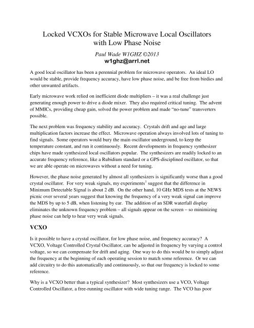
<strong>Locked</strong> <strong>VCXOs</strong> <strong>for</strong> <strong>Stable</strong> <strong>Microwave</strong> <strong>Local</strong> <strong>Oscillators</strong><br />
<strong>with</strong> Low Phase Noise<br />
Paul Wade <strong>W1GHZ</strong> ©2013<br />
w1ghz@arrl.net<br />
A good local oscillator has been a perennial problem <strong>for</strong> microwave operators. An ideal LO<br />
would be stable, provide frequency accuracy, have low phase noise, and be free from birdies and<br />
other unwanted artifacts.<br />
Early microwave work relied on inefficient diode multipliers – it was a real challenge just<br />
generating enough power to drive a diode mixer. They also required critical tuning. The advent<br />
of MMICs, providing cheap gain, solved the power problem and made “no-tune” transverters<br />
possible.<br />
The next problem was frequency stability and accuracy. Crystals drift and age and large<br />
multiplication factors increase the effect. <strong>Microwave</strong> operation always involved lots of tuning to<br />
find signals. Some operators would bury the main oscillator underground, to keep the<br />
temperature constant, and run it continuously. Recent developments in frequency synthesizer<br />
chips have made synthesized local oscillators popular. The synthesizers are readily locked to an<br />
accurate frequency reference, like a Rubidium standard or a GPS-disciplined oscillator, so that<br />
we are able operate on microwaves <strong>with</strong>out a need <strong>for</strong> tuning.<br />
However, the phase noise generated by almost all synthesizers is significantly worse than a good<br />
crystal oscillator. For very weak signals, my experiments 1 suggest that the difference in<br />
Minimum Detectable Signal is about 2 dB. On the other hand, 10 GHz MDS tests at the NEWS<br />
picnic over several years suggest that knowing the frequency of a very weak signal can improve<br />
the MDS by up to 5 dB, when listening by ear. The addition of an SDR waterfall display<br />
eliminates the unknown frequency problem – all signals appear on the screen – so minimizing<br />
phase noise can help to hear very weak signals.<br />
VCXO<br />
Is it possible to have a crystal oscillator, <strong>for</strong> low phase noise, and frequency accuracy A<br />
VCXO, Voltage Controlled Crystal Oscillator, can be adjusted in frequency by varying a control<br />
voltage, so we can compensate <strong>for</strong> drift and aging. One way to do this would be to simply adjust<br />
the frequency at the beginning of each operating session to match some reference. Or we can<br />
add circuitry to do this automatically and continuously, so that our frequency is locked to some<br />
reference.<br />
Why is a VCXO better than a typical synthesizer Most synthesizers use a VCO, Voltage<br />
Controlled Oscillator, a free-running oscillator <strong>with</strong> wide tuning range. The VCO has poor
inherent stability <strong>with</strong>out the synthesizer controlling it, and the wide tuning range makes it very<br />
sensitive to noise.<br />
As an example, a typical local oscillator frequency <strong>for</strong> 1296 MHz operation is 1152 MHz. A<br />
synthesizer <strong>for</strong> this frequency might use a VCO like the Minicircuits ROS-1285-119+, which<br />
tunes from 1115 to 1285 MHz <strong>for</strong> a tuning voltage of 0 to 5 volts. Tuning sensitivity is specified<br />
as about 56 MHz per volt – one microvolt of noise will move the frequency by 56 Hz, and a<br />
millivolt of noise will move the frequency by 56 KHz. A VCXO has much lower tuning<br />
sensitivity; I measured a 96 MHz VCXO to vary 16.5 KHz <strong>for</strong> a tuning voltage of 0 to 3.3 volts,<br />
so the tuning sensitivity is about 5 KHz per volt, roughly 10,000 times less sensitive. When<br />
multiplied by 12 to 1152 MHz, the tuning sensitivity is about 60 KHz per volt, still 1000 times<br />
better than the VCO. One millivolt of noise will move the VCXO frequency by 60 Hz, or the<br />
VCO frequency by 56 KHz. Even one microvolt of noise will move the VCO frequency by 56<br />
Hz. Any noise voltage is constantly moving the oscillator frequency around – we call it phase<br />
noise. In real equipment, it is easy to keep noise well below a millivolt, but getting below a<br />
microvolt is a lot harder. It is really hard to keep the noise on the tuning voltage low enough to<br />
eliminate it as a source of phase noise (of course, there are other sources).<br />
Frequency Synthesizers<br />
A frequency synthesizer generates a desired frequency by comparing the frequency of the<br />
oscillator in the synthesizer <strong>with</strong> a reference frequency and correcting the oscillator frequency<br />
until it is on the desired frequency. Since the desired frequency is not the same as the reference<br />
(otherwise the synthesizer is not required), the frequencies must be converted to a common<br />
frequency <strong>for</strong> comparison. One technique is to generate harmonics of the reference and do the<br />
comparison at the oscillator frequency. A more common and versatile technique, shown in<br />
Figure 1, is to digitally divide one or both frequencies to a lower common frequency and then<br />
compare.<br />
Figure 1 – Simplified Frequency Synthesizer
Some of the division schemes can get pretty fancy, in order to generate a wide range of<br />
frequencies <strong>with</strong> very small step increments, and to change frequencies quickly. Most of them<br />
also use some <strong>for</strong>m of processor chip. All of this tends to generate digital noise.<br />
For the VCXO, we are making a very simple synthesizer, hard-wired <strong>for</strong> one specific frequency.<br />
The goal is to generate a clean, stable signal. For simplicity, only integer dividers are used,<br />
using ordinary CMOS logic devices. This limits the choice of frequencies, but only a limited<br />
number of VCXO devices are readily available; however, several of them are quite useful <strong>for</strong><br />
microwave <strong>Local</strong> <strong>Oscillators</strong>.<br />
The perceived wisdom <strong>for</strong> minimizing phase noise in synthesizers includes:<br />
• A stable oscillator <strong>with</strong> small tuning range<br />
• High comparison frequency<br />
• Integer dividers<br />
• Slow loop filter time constant<br />
• Clean, stable power supply<br />
I have tried to incorporate all of these in the VCXO circuit.<br />
VCXO Board<br />
The schematic of the VCXO board is shown in Figure 2. The board assumes a packaged VCXO,<br />
but it could also control a homebrew one to operate at some other frequency. The VCXO<br />
frequency range is roughly 50 to 200 MHz, and the CMOS logic is only guaranteed to operate up<br />
to about 30 MHz, so the first divider is a prescaler chip. Several prescalers fit in this location,<br />
allowing divide ratios of 2 to 80, selected by three selection pins. The prescalers will operate up<br />
to at least 1100 MHz, so higher frequency oscillators are also possible. After the prescaler, two<br />
CMOS logic chips are available – U5 can be wired <strong>for</strong> any divisor between 2 and 16, while U6<br />
has two sections each <strong>with</strong> fixed divisors of 2 and 5. To divide by 28, <strong>for</strong> example, one chip<br />
would divide by 14 and the other by 2. All the dividers are programmed by jumper wires –<br />
simple, effective, and fine <strong>for</strong> fixed frequency operation.<br />
The programmable divider sections may be used <strong>for</strong> either the oscillator frequency or the<br />
reference frequency, in order to arrive at a common frequency. Examples will be shown <strong>for</strong> all<br />
the useful VCXO frequencies that I have found. At the common frequency, both signals go to<br />
the comparator – this is a logical Exclusive-OR (XOR) gate. The XOR gate output is high when<br />
both signals are the same and low when they are different. When the frequencies are the same,<br />
the output will be high <strong>for</strong> part of each cycle and low <strong>for</strong> part of each cycle. The output is<br />
averaged to create a DC tuning voltage which just happens to be the voltage <strong>for</strong> the desired<br />
frequency. If the frequencies were different, the voltage would be higher or lower, <strong>for</strong>cing the<br />
oscillator toward the desired frequency.
Figure 2 – <strong>Microwave</strong> VCXO Board Schematic
The output averaging is done in the loop filter, an RC filter <strong>with</strong> a long time constant, so that the<br />
oscillator is gently guided onto frequency. During testing, I can see the oscillator wave<strong>for</strong>m on<br />
an oscilloscope shift frequency over several seconds to line up <strong>with</strong> the reference wave<strong>for</strong>m.<br />
Finally, there is a MMIC buffer amplifier <strong>for</strong> the oscillator output.<br />
While all my examples use a 10 MHz reference frequency, other references can also work. If<br />
you have a good reference oscillator at another frequency, use it. Only integer dividers are<br />
available, so an integer VCXO requires an integer reference. On the other hand, to lock an odd<br />
frequency, perhaps <strong>for</strong> a beacon, an odd reference is required that can achieve a common<br />
reference frequency. A couple of possibilities are a programmable Rubidium source or a reverse<br />
DDS source.<br />
VCXO Examples<br />
80 MHz – The simplest example is an 80 MHz VXCO, useful as the LO source to multiply to<br />
2160 MHz (2304), 3600 MHz (3456), and 10800 MHz (10368). The board is shown in Figure 3<br />
– 80 MHz is divided by 8 in the MC12093 prescaler chip (select ÷ 8 by grounding pins 3 and 6)<br />
to 10 MHz, then compared directly <strong>with</strong> the 10 MHz reference. This board locks right up <strong>with</strong> a<br />
clean output.<br />
Figure 3 – 80 MHz VCXO Board
96 MHz – Another very useful frequency is 96 MHz, which is multiplied to 1152 MHz <strong>for</strong> the<br />
popular LO <strong>for</strong> 1296, <strong>with</strong> harmonics providing markers on many microwave bands. On the<br />
board shown in Figure 4, 96 MHz is divided by 8 in the MC12093 prescaler chip to 12 MHz.<br />
Then we must divide by 12 to 1 MHz, and divide the 10 MHz reference by 10 to compare at 1<br />
MHz. I tried dividing by 12 directly in the 74HC193 chip, but the output was very asymmetric,<br />
<strong>with</strong> only a narrow pulse – this would not work well <strong>with</strong> the XOR comparator. Instead, the<br />
74HC193 is wired to divide by six, followed by a divide by two in the 74HC390 chip – a divideby-two<br />
always generates a square wave output. Other sections of the 74CH390 divide the 10<br />
MHz reference by five, then two, to provide a square wave as well. This board also locks right<br />
up; the output has small spurs 1 MHz on each side of the main output.<br />
The divisor of the74HC193 chip, U5, is programmed by the ABCD jumpers on the right side or<br />
the board <strong>with</strong> the binary version of the divisor. For instance, a divisor of 12 = 1100 binary, so<br />
jumpers A and B are wired HIGH, to +5volts, and jumpers C and D are wired LOW, to ground.<br />
The board in Figure 4 is wired <strong>for</strong> a divisor of 6 = 0110 binary.<br />
Figure 4 – 96 MHz VCXO board
The bottom of the board, shown in Figure 5, has the wiring connections to divide the 10 MHz<br />
reference by 10 to 1 MHz. The input <strong>for</strong> the 10 MHz reference is at location X5.<br />
Figure 5 – Bottom side of 96 MHz VCXO board
200 MHz – provides a stable LO <strong>for</strong> 222 MHz; once you get away from 28 MHz, any IF is good.<br />
This one, shown in Figure 6, is nearly as simple as the 80 MHz, requiring only a prescaler. The<br />
prescaler is changed to a MC12080 programmed to divide by 20 <strong>for</strong> 10 MHz output. Selection<br />
of divide-by-20 requires changing pin 3 from ground to high, by cutting the PCB trace and<br />
adding a jumper wire to pin 2. This board locks right up <strong>with</strong> a clean output.<br />
Figure 6 – 200 MHz VCXO board
120 MHz – provides a stable LO <strong>for</strong> 144 MHz. As shown in Figure 7, the prescaler is a<br />
MC12080 programmed to divide by 10, to 12 MHz. Selection of divide-by-10 requires changing<br />
both pins 3 and 6 from ground to high, by cutting the PCB traces and adding jumper wires from<br />
pin 3 to pin 2 and from pin 6 to pin 7. The rest of the wiring is the same as the 96 MHz board.<br />
This board also locks right up; the output has small spurs 1 MHz on each side of the main output.<br />
Figure 7 – 120 MHz VCXO board<br />
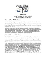
108 MHz – I haven’t yet found a VCXO <strong>for</strong> this frequency, but WA1MBA says it would be a<br />
useful frequency, and it provides another example. The prescaler must divide by 9 to 12 MHz;<br />
the MC12026 can be programmed <strong>for</strong> this. The rest of the wiring is the same as the 96 MHz<br />
board.
Multiplier Board<br />
To multiply from the VCXO board to the microwave LO frequency, I use the LO boards <strong>for</strong> my<br />
simple rover transverters 2 , replacing the oscillator <strong>with</strong> the signal from the VCXO board. The 80<br />
MHz VCXO drives the 720 MHz LO board – the frequency is further multiplied in the 2304 or<br />
3456 MHz transverter. The multiplier board in photo in Figure 8 shows the input from the<br />
VCXO bypassing the oscillator section.<br />
Figure 8 – 720 MHz LO Multiplier board configured <strong>for</strong> external VCXO<br />
The 1152 MHz LO board originally used a 64 MHz crystal oscillator. To operate <strong>with</strong> 96 MHz<br />
input from the VCXO, the filter after the first tripler must be tuned to 288 MHz. With the 64<br />
MHz oscillator, the combline filter was tuned to 192 MHz by capacitive loading of 36 pf (two 18<br />
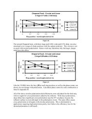
pf capacitors in parallel <strong>for</strong> lower loss). From the chart, Figure 7, in my transverter article 2 , I<br />
estimated the required capacitance <strong>for</strong> 288 MHz as 22 pf. The filter response in Figure 9 shows<br />
that the filter is tuned slightly high, <strong>with</strong> 288 MHz at the edge of the response. Increasing the<br />
capacitance to 23 pf, an18 pf in parallel <strong>with</strong> 5 pf, centered the filter near 288 MHz. The parallel<br />
capacitors slightly reduced the loss. The input connection to this multiplier board, shown in<br />
Figure 10, is similar to the one in Figure 8.
Combline Filter - 288 MHz<br />
dB<br />
5<br />
0<br />
-5<br />
-10<br />
-15<br />
-20<br />
-25<br />
-30<br />
-35<br />
250 260 270 280 290 300 310 320 330 340 350<br />
Frequency in MHz<br />
22 pf<br />
18 + 5 pf<br />
Figure 9 – Response of Combline Filter <strong>for</strong> 288 MHz<br />
Figure 10 – 1152 MHz multiplier board configured <strong>for</strong> external 96 MHz VCXO input
Phase Noise<br />
While there is no reason to expect the VCXO to be more stable than a synthesizer, our goal is to<br />
reduce phase noise. I only have data on the 80 MHz version. Figure 11 shows the phase noise<br />
starting <strong>with</strong> a pretty good TCXO, the 80 MHz VCXO, and the VCXO multiplied to 720 MHz.<br />
We expect an 8 times multiplication to add about 18 dB of phase noise – the 80 MHz VCXO has<br />
about 18 dB more phase noise in the mid-range, but is somewhat worse at very low offset<br />
frequencies. A further 9 times multiplication to 720 MHz should add another 19 dB, which we<br />
can see in the mid-range as well. The 720 MHz curve generally has the same shape as the 10<br />
MHz source, so most of the difference is due to frequency multiplication. Figure 12 compares<br />
the VCXO-based 720 MHz LO <strong>with</strong> one using an ordinary crystal oscillator. The VCXO is a few<br />
dB worse, but still really good.<br />
Figure 11 – Phase Noise of VCXO LO, showing increase <strong>with</strong> Frequency Multiplication
Figure 12 – Comparison of 720 MHz LO <strong>with</strong> Crystal and VCXO as source<br />
An LO <strong>for</strong> 1152 MHz, starting <strong>with</strong> a 96 MHz VCXO, also looks very good. In Figure 13, we<br />
can see the phase noise <strong>for</strong> the same 10 MHz TCXO, the locked 96 MHz VCXO, and the 1152<br />
MHz output from the multiplier board. The same phase noise multiplication <strong>with</strong> frequency<br />
multiplication is evident.<br />
Figure 13 – Phase Noise of 1152 MHz VCXO from locked 96 MHz VCXO
The two VCXO-base LO chains are compared in Figure 14. We would expect the 1152 MHz<br />
phase noise to be about 4 dB worse due to the greater frequency multiplication. However, the<br />
1152 MHz phase noise is lower than the 720 MHz version. A possible explanation is different<br />
crystals – the 80 MHz VCXO is made by Crystek, while the 96 MHz VCXO is made by<br />
Abracon.<br />
Figure 14 – Phase noise of both VCXO-based LO chains<br />
How do the VCXO-based LO chains compare <strong>with</strong> a synthesized LO Figure 15 shows a<br />
comparison <strong>with</strong> several popular synthesizers, all operating at 1152 MHz. With this correction,<br />
the VCXO is at least 10 dB better than the best synthesizers in the important frequency offset<br />
range, the SSB passband. The most common synthesizers, the ApolLO (curve marked N5AC<br />
A32) and the Qualcomm, have phase noise nearly 40 dB worse than the VCXO.
Figure 15 - Comparison of VCXO LO <strong>with</strong> several Synthesizers<br />
The ApolLO synthesizer was used <strong>for</strong> the MDS tests 1 that showed a 2 dB difference from a<br />
crystal oscillator LO – and the difference in phase noise is ~40 dB. Would some of the better<br />
synthesizers, only 10 or 20 dB worse than a crystal source, be any different in MDS Clearly,<br />
more work is needed.<br />
One problem is that I do not have equipment <strong>for</strong> phase noise measurement – measurement of the<br />
very low phase noise of a good oscillator is difficult. I rely on test equipment at various<br />
conferences. The results here were measured at the Eastern VHF/UHF Conference in 2012 and<br />
2013, and at <strong>Microwave</strong> Update 2012. A few oscillators are measured at all three sessions to<br />
insure that the results are comparable. Special thanks are due to the folks who provide and<br />
operate this specialized test equipment, particularly Greg Bonaguide, WA1VUG, of Rohde &<br />
Schwarz.
Spurious<br />
On the versions that divide down to 1 MHz comparison frequency, like the 96 MHz version, I<br />
found small spurs 1 MHz on each side of the VCXO frequency. The spurs were about 65 dB<br />
down, but grew significantly larger after multiplication to 1152 MHz. I suspected inadequate<br />
bypassing – the 0.1 µF capacitors at each chip are not enough to be effective at low frequencies.<br />
A quick experiment showed that the problem was at the VCXO power pin rather than the tuning<br />
voltage.<br />
I added a 1 µF chip capacitor at the VCXO and at each IC <strong>with</strong> a 1 MHz signal. The spurs were<br />
reduced to about 72 dB down, and a similar amount after multiplication. This still isn’t good<br />
enough, so I put the VCXO on a separate board <strong>with</strong> separate voltage regulator in a separate<br />
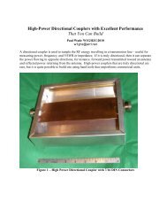
enclosure, shown in Figure 16. I added a Minicircuits directional coupler (door prize at some<br />
conference) to pick off some signal <strong>for</strong> the prescaler on the other board<br />
Figure 16 – VCXO on separate board <strong>with</strong> buffer amp and directional coupler<br />
Another choice might be to use a 12 MHz reference, eliminating the 1 MHz component entirely.<br />
This could be provided by locking a 12 MHz VCXO to GPS 3 .
The complete 1152 MHz LO is shown in Figure 17, packaged up as the start of a new 1296 MHz<br />
transverter. When I did the initial assembly, the power output at 1152 MHz was quite low.<br />
After some experimentation, I found that the harmonics of 96 MHz in the VCXO output were<br />
causing low output from the multiplier board. A low-pass filter eliminates the harmonics – I<br />
found one in the junkbox <strong>for</strong> 115 MHz which works just fine, but it wouldn’t be hard to make an<br />
adequate filter <strong>with</strong> a few coils and capacitors.<br />
Figure 17 – Complete packaged 1152 MHz LO based on locked 96 MHz VCXO<br />
I did not notice any problem <strong>with</strong> VCXO harmonics in the 720 MHz LO chain, shown in Figure<br />
18, but it used an early prototype board. I’ll have to check this out further.
Construction<br />
Figure 18 – Complete packaged 720 MHz LO based on locked 80 MHz VCXO<br />
Construction is fairly straight<strong>for</strong>ward, <strong>with</strong> almost all of the components on the top side of the<br />
board, except <strong>for</strong> a few 1 µF chip capacitors on the bottom side to <strong>for</strong> better bypassing of the 1<br />
MHz signal in some of the dividers. The VCXO and prescaler are only available in surfacemount<br />
versions, and a few of the higher frequency components around them are also surface<br />
mount. The rest of the components are traditional thru-hole.<br />
The Crystek VCXO shown in Figure 3 has four solder pads, matching the PC board, while the<br />
Abracon ABLJO-V VCXO used at the other frequencies have six pads. However, the middle<br />
ones are unused, so both types fit the PC board. I put a tiny dab of rosin paste flux on the VCXO<br />
pads be<strong>for</strong>e soldering. A VCXO is moderately expensive, but so are quality crystals.<br />
Not all the ICs are needed <strong>for</strong> all options, and different prescalers are needed, as mentioned<br />
above. The final step is programming by soldering iron, adding the wires to select the<br />
appropriate divisors to bring the VCXO and reference frequencies to a common comparison<br />
frequency, <strong>with</strong> details in Appendix A. Appendix B is a parts list.
The 1 µF chip capacitors, C18 thru C22, reduce the switching noise and resultant spurious<br />
signals in the versions <strong>with</strong> a 1 MHz comparison frequency, like 96 MHz. C18 can be seen in<br />
Figure 4, attached to the PC trace between U8 and the VCXO; the green soldermask must be<br />
scraped off the trace be<strong>for</strong>e it can be soldered. C19-22 are on the back side of the board, shown<br />
in Figure 5.<br />
Other frequencies are certainly possible, but may require homebrewing your own VCXO. For<br />
instance, Down East <strong>Microwave</strong> has instructions <strong>for</strong> the crystal oscillator in some of their older<br />
transverters; this may be useful since crystals do tend drift slightly <strong>with</strong> aging. For odd<br />
frequencies that are not easily divided to 10 MHz, an odd reference frequency may be provided<br />
by a programmable Rubidium standard or by a reverse-DDS scheme 4 .<br />
Output power at J2 is typically +3 to +5 dBm. It may be increased a bit by reducing the value of<br />
R3 – in my two piece version, R3 is 180 ohms and the output is about +10 dBm. This also<br />
increases the drive voltage to the prescaler, which should be 1000 millivolts max peak-to-peak<br />
(and at least 400 mV p-p); I used a directional coupler in the two-piece version to reduce the<br />
prescaler drive voltage.<br />
PC boards are available.<br />
Summary<br />
A local oscillator chain sourced from a locked VCXO can provide the frequency accuracy and<br />
stability of a good reference oscillator while maintaining the low phase noise of a crystal<br />
oscillator. Measured phase noise is 20 to 40 dB better than available synthesized local<br />
oscillators. Good packaged <strong>VCXOs</strong> are available <strong>for</strong> a few desirable frequencies at a cost<br />
comparable to a quality quartz crystal. Further experimentation is needed to determine whether<br />
the final system per<strong>for</strong>mance is significantly better than a good synthesizer.<br />
Notes<br />
1. Paul Wade, <strong>W1GHZ</strong>, “Phase Noise and MDS,” Proceedings of <strong>Microwave</strong> Update 2009,<br />
ARRL, 2009, pp. 193-196.<br />
2. Paul Wade, <strong>W1GHZ</strong>, “Multiband <strong>Microwave</strong> Transverters <strong>for</strong> the Rover – Simple and<br />
Cheap,” Proceedings of <strong>Microwave</strong> Update 2008, ARRL, 2008, pp. 40-67.<br />
3. Paul Wade, <strong>W1GHZ</strong>, “A Flexible VCXO Locking Board,” Proceedings of <strong>Microwave</strong><br />
Update 2012, ARRL, 2012, pp. 101-113.<br />
4. http://myweb.tiscali.co.uk/g4nns/RevDDS.html and<br />
http://www.microwaves.dsl.pipex.com/RDDS/RDDSINDX.htm
Appendix A<br />
<strong>Microwave</strong> VCXO Board Programming<br />
Freq VCXO DigiKey Prescaler Prescale Divide ABCD* ÷2 Signal Comparison Ref ÷5 Ref ÷2 Reference<br />
74HC193 74HC390 Frequency 74HC390 74HC390<br />
80 MHz Crystek 744-1214-ND MC12093 ÷8 na na na Q->Z 10 MHz na na 10MHz->REF<br />
80 MHz Abracon 535-11429-ND MC12093 ÷8 na na na Q->Z 10 MHz na na 10MHz->REF<br />
96 MHz Abracon 535-11431-ND MC12093 ÷8 ÷6 LHHL Q2->X4 Y2->Z 1 MHz 10MHz->X5 Y5->X6 Y6->REF<br />
100 MHz Abracon 535-11433-ND MC12080 ÷10 na na na Q->Z 10 MHz na na 10MHz->REF<br />
120 MHz Abracon 535-11437-ND MC12080 ÷10 ÷6 LHHL Q2->X4 Y2->Z 1 MHz 10MHz->X5 Y5->X6 Y6->REF<br />
200 MHz Abracon 887-1543-1-ND MC12080 ÷20 na na na Q->Z 10 MHz na na 10MHz->REF<br />
108 MHz homebrew MC12026 ÷9 ÷6 LHHL Q2->X4 Y2->Z 1 MHz 10MHz->X5 Y5->X6 Y6->REF<br />
NOTES:<br />
Y5->X6 means add a wire from point y5 to point X6, etc.<br />
* ABCD = LHHL: L is ground, H is +5 Volts<br />
na means not applicable - chip may be left out<br />
MC12093 ÷8: pins 3 and 6 grounded (unmodified board) Digikey MC12080DGOS-ND<br />
MC12080 ÷10: pins 3 and 6 high (jumpers to pins 2 and 7) Digikey MC12093DGOS-ND<br />
MC12080 ÷20: pins 3 grounded (unmodified) and pin 6 high (jumper to pin 7)<br />
MC12026 Digikey MC12026ADGOS-ND<br />
Crystek VCXO are CVHD-950 series<br />
Abracon VCXO are ABLJO-V series<br />
Phase Comparator 74AC86 compares Z and REF inputs, which must be at same frequency<br />
PC Boards marked 2013a are good <strong>for</strong> all frequencies<br />
PC Boards marked 2012 are good <strong>for</strong> 80, 100, and 200 MHz. A wire is needed from Pin 1 of U4 (LT116) to +5 Volts.
Appendix B – Parts List<br />
Refdes Value Description Digikey Mouser<br />
A1<br />
MAR-<br />
3SM MMIC Minicircuits<br />
C1 1 uF electrolytic P14054-ND<br />
C2 100 uF electrolytic P5123-ND<br />
C3,7,8,9,11,16,17 0.1 uF<br />
C4,5,14 1000pf chip<br />
C6,15 0.1 uF chip<br />
C10 0.33 uF 478-3194-ND<br />
C12 10 uF P813-ND<br />
C13 100 pf chip<br />
C18-22 1 uF chip 478-5906-1-ND<br />
581-<br />
SR215C104K<br />
581-<br />
SR215E334M<br />
R1 82K 1/4 watt CF14JT82K0CT-ND<br />
R2 12K 1/4 watt<br />
R3 390 chip<br />
R4 91 chip<br />
R5,6 820 chip<br />
R7 91 1/4 watt<br />
U1 VCXO see Appendix A<br />
U2 Prescaler see Appendix A<br />
U3 LT1116 LT1116CN8*PBF-ND<br />
U4 74AC86 296-4345-5-ND 512-74AC86PC<br />
U5 74HC193 296-8262-5-ND<br />
U6 74HC390 296-9199-5-ND<br />
U7 7805 78L05 adequate <strong>for</strong> 80 MHz version<br />
U8 78L3.3 497-7287-1-ND