

vtitan x Veriton X490g&X498g&X490 book.book
vtitan x Veriton X490g&X498g&X490 book.book
vtitan x Veriton X490g&X498g&X490 book.book

Create successful ePaper yourself
Turn your PDF publications into a flip-book with our unique Google optimized e-Paper software.
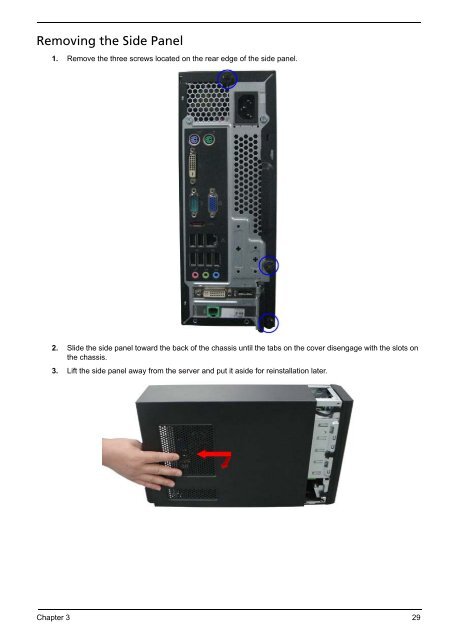
Removing the Side Panel<br />
1. Remove the three screws located on the rear edge of the side panel.<br />
2. Slide the side panel toward the back of the chassis until the tabs on the cover disengage with the slots on<br />
the chassis.<br />
3. Lift the side panel away from the server and put it aside for reinstallation later.<br />
Chapter 3 29
Removing the Front Bezel<br />
1. Release the front bezel from the chassis interior.<br />
2. Pull the bezel away from the chassis.<br />
30 Chapter 3
Removing the Heat Sink Fan Assembly<br />
WARNING:The heat sink becomes very hot when the system is on. NEVER touch the heat sink with any metal<br />
or with your hands.<br />
1. Use a long-nosed screwdriver to loosen the four screws on the heat sink, in the order as shown below.<br />
2. Lift the heat sink fan assembly away from the mainboard.<br />
3. Lay down the heat sink fan assembly, in an upright position, on top of the optical drive, as shown below,<br />
then disconnect the fan cable from the mainboard.<br />
4. Use an alcohol pad to wipe off the thermal grease from both the heat sink and the processor.<br />
Chapter 3 31
Removing the Processor<br />
IMPORTANT:Before removing a processor from the mainboard, make sure to create a backup file of all<br />
important data.<br />
WARNING:The processor becomes very hot when the system is on. Allow it to cool off first before handling.<br />
1. Release the load lever.<br />
2. Lift the load lever and load plate to the fully open, upright position (1) and (2).<br />
3. Pull out the processor from the socket.<br />
IMPORTANT: If you are going to install a new processor, note the arrow on the corner to make sure the<br />
processor is properly oriented over the socket.<br />
32 Chapter 3
Removing the Optical Drive<br />
1. Disconnect the data and power cables from the rear of the optical drive.<br />
2. Slide lock handle toward the right until the lock handle no removing as show below.<br />
3. Pull the drive out of the drive bay.<br />
Chapter 3 33
Removing the Hard Disk Drive<br />
1. Disconnect the data and power cables from the rear of the hard drive.<br />
2. Disconnect the other end of the data cable(HDD and ODD) from the mainboard.<br />
3. Remove the HDD-ODD bracket.<br />
a. Remove the screw that secures the HDD bracket to the chassis.<br />
34 Chapter 3
. Remove the two screw from chassis.<br />
c. Lift the bracket up and turn it over.<br />
4. Place the bracket on a clean, static-free work surface.<br />
5. Use two fingers to press the HDD bracket then pull the bracket up.<br />
Chapter 3 35
6. Take out the HDD module<br />
a. Use a hand to open out the HDD bracket until the hook of HDD bracket away from the HDD screw<br />
bore. then use other hand to take out the HDD module.<br />
36 Chapter 3
Removing the Power Supply<br />
1. Disconnect the 4-pin and 24-pin power supply cables from the mainboard.<br />
2. Remove the screw that secures the power supply to the chassis.<br />
3. Remove the two screws that secure the power supply to the rear panel.<br />
4. Remove the four screws that secures the power supply to the chassis.<br />
Chapter 3 37
5. Lift the power supply module out of the chassis.<br />
38 Chapter 3
Removing the VGA Card<br />
1. Remove the screw that secures the card to the chassis.<br />
2. Press the clip toward under.<br />
3. Gently pull the card to remove it from the mainboard.<br />
Chapter 3 39
Removing the Memory Modules<br />
IMPORTANT:Before removing any DIMM from the memory board, make sure to create a backup file of all<br />
important data.<br />
1. Press the holding clips on both sides of the DIMM slot outward to release the DIMM(1).<br />
2. Gently pull the DIMM upward to pull it away from the M/B(2).<br />
40 Chapter 3
Removing the Front I/O and Card Reader Boards<br />
1. Disconnector the the USB and audio cables from the mainboard.<br />
2. Open the cable retention clip,then take out these cables.<br />
3. Remove the front I/O and card reader board bracket.<br />
a. Removing the screw from chassis.<br />
Chapter 3 41
. Pull the front I/O and USB assembly from chassis.<br />
4. Remove the card reader board.<br />
a. Remove the two screws that secure the card reader board to the bracket.<br />
b. Pull the card reader board out of the bracket.<br />
42 Chapter 3
5. Remove the front I/O board.<br />
a. Remove the two screws that secure the I/O board to the bracket.<br />
b. Pull the I/O board out of the bracket.<br />
Chapter 3 43
Removing the Intrusion Alarm Cable<br />
1. Disconnector the intrusion alarm from the motherboard.<br />
2. Removing the intrusion alarm assembly.<br />
a. Removing the two screws from the chassis.<br />
b. Release the intrusion alarm assembly from the chassis.<br />
44 Chapter 3
Removing the Power Switch,OBR and LED Cable Assembly<br />
1. Disconnector the power switch,OBR and LED cable from mianboard.<br />
2. Removing the OBR and LED cable assembly.<br />
a. Release the locking tabs from the chassis interior.<br />
b. Pull the OBR and LED cable assembly from the chassis.<br />
Chapter 3 45
3. Removing the power cable assembly.<br />
a. Release the locking tabs from the chassis interior.<br />
b. Pull the power button assembly from the chassis<br />
46 Chapter 3
Removing the Mainboard<br />
1. Remove the eight screws that secure the mainboard to the chassis.<br />
Note:Circuit boards >10 cm² has been highlighted with the yellow rectangle as above image shows.<br />
Please detach the Circuit boards and follow local regulations for disposal.<br />
2. Lift the board from the chassis.<br />
Chapter 3 47
3. Punching in IO Shield then you can remove it.<br />
4. Remove the RTC battery.<br />
Note:RTC battery has been highlighted with the yellow circle as above image shows.Please detach the<br />
RTC battery and follow local regulations for disposal.<br />
48 Chapter 3
Jumper and Connector Information<br />
M/B Placement<br />
Chapter 5<br />
Chapter 5 56
Jumper Setting<br />
The section explains how to set jumper for correct configuration of the mainboard.<br />
Setting Jumper<br />
Use the motherboard jumpers to set system configuration options. Jumpers with more Than one pin are<br />
numbered. When setting the jumpers, ensure that the jumper caps are Placed on the correct pins.<br />
System Board Jumper Setting<br />
Jumper Type Description Setting (default) Picture<br />
CLR_CMOS 3-pin CLEAR CMOS 1-2: NORMAL<br />
2-3: CLEAR<br />
Before clearing the CMOS, make<br />
sure to turn the system off.<br />
ME_DISABLE 3-pin MEDISABLE 1-2: NORMAL<br />
2-3: MEDISABLE<br />
BIOS_WP 3-pin BIOS FLASH<br />
PROTECT<br />
1-2: NORMAL<br />
2-3: BIOS_WP<br />
Chapter 5 58
System Board Header Setting<br />
Refer to the following for information on connecting the motherboard’s header setting.<br />
SATA1~3: Serial ATA connectors<br />
These connectors are used to support the new Serial ATA devices for the highest data transfer rates (3.0 Gb/<br />
s), simpler disk drive cabling and easier PC assembly. It eliminates limitations of the current Parallel ATA<br />
interface. But maintains register compatibility and software compatibility with Parallel ATA.<br />
Pin Signal Name Pin Signal Name<br />
1 Ground 2 TX+<br />
3 TX- 4 Ground<br />
5 RX- 6 RX+<br />
7 Ground - -<br />
59 Chapter 5
<strong>Veriton</strong> <strong>X490</strong>G/X498G/<strong>X490</strong> Exploded Diagram<br />
NOTE: This section will be updated when more information becomes available.<br />
ITEM NAME Q’TY ITEM NAME Q’TY<br />
1 CHASSIS 1 10 BEZEL 1<br />
2 TOP-PANEL 1 11 Cardreader PCB MODULE 1<br />
3 POWER SUPPLY 1 12 HDD-SWITCH-HOLDER 1<br />
4 MOTHER BOARD 1 13 SWITCH HOLDER 1<br />
5 ODD-HDD-BRAKET MODULE 1 14 INTRUSSION-SWITCH<br />
6 LINE-CLIP 1 15 RUBBER FOOT 8<br />
7 CD-ROM 1 16 HDD MODULE 1<br />
8 USB PLATE 1 17 INTERNAL SPEAKER 1<br />
9 USB PCB MODULE 1<br />
67 Chapter 6
<strong>Veriton</strong> <strong>X490</strong>G/X498G/<strong>X490</strong> FRU List<br />
MB kit<br />
Bezel<br />
Chassis<br />
Cooler<br />
CPU<br />
Memory<br />
Category Description Part Number<br />
MB Kit V<strong>X490</strong> Intel H57 Intel 82578DC Acer Logo uATX N/A<br />
W/O 1394 LF Eup Lot6<br />
MB.VAU07.002<br />
XSFF BEZEL for New <strong>Veriton</strong> X Serial PZ.11900.141<br />
xSFF CHASSIS for New <strong>Veriton</strong> X Serial HS.13100.098<br />
CM iCooler LGA1156 w/i pure al 93x93x40h w/i 9225 fan w/o<br />
75mm duct<br />
HI.10800.059<br />
Cooler Intel LGA1156 FXC PKP775G01U22 w/o duct HI.10800.051<br />
Core i7-870 (2.93G 8M 1333FSB), Lynnfield, B-1, 95W KC.87001.CI7<br />
Core i7-860 (2.80G 8M 1333FSB), Lynnfield, B-1, 95W KC.86001.CI7<br />
Core i5-750 (2.66G 8M 1333FSB), Lynnfield, B-1, 95W KC.75001.CI5<br />
Core i5-670 (3.46G 4M 1333FSB), Clarkdale, 73W KC.67001.CI5<br />
Core i5-661 (3.33G 4M 1333FSB), Clarkdale, 87W KC.66101.CI5<br />
Core i5-660 (3.33G 4M 1333FSB), Clarkdale, 73W KC.66001.CI5<br />
Core i5-650 (3.2G 4M 1333FSB), Clarkdale, 73W KC.65001.CI5<br />
Core i3-540 (3.06G 4M 1333FSB), Clarkdale, 73W KC.54001.CI3<br />
Core i3-530 (2.93G 4M 1333FSB), Clarkdale, 73W KC.53001.CI3<br />
Pentium G6950 (2.8G 3M 1066FSB), Clarkdale, 73W KC.69501.DEG<br />
1GB, DDRIII1333 KN.1GB0B.030<br />
1GB, DDRIII1333 KN.1GB0B.036<br />
1GB, DDRIII1333 KN.1GB03.032<br />
1GB, DDRIII1333 KN.1GB0H.015<br />
1GB, DDRIII1333 KN.1GB0G.024<br />
1GB, DDRIII1333 KN.1GB01.031<br />
Chapter 6 68
HDD<br />
ODD<br />
VGA<br />
Category Description Part Number<br />
2GB, DDRIII1333 KN.2GB0B.014<br />
2GB, DDRIII1333 KN.2GB0B.024<br />
2GB, DDRIII1333 KN.2GB03.016<br />
2GB, DDRIII1333 KN.2GB0H.009<br />
2GB, DDRIII1333 KN.2GB0G.015<br />
2GB, DDRIII1333 KN.2GB01.025<br />
HDD SEAGATE 3.5" 7200rpm 320GB ST3320418AS(<br />
Pharaoh) SATA II 16MB LF F/W:CC44<br />
HDD SEAGATE 3.5" 7200rpm 500GB<br />
ST3500418AS(Pharaoh) SATA II 16MB LF F/W:CC44<br />
HDD SEAGATE 3.5" 7200rpm 750GB ST3750528AS (<br />
Pharaoh) SATA II 32MB LF F/W:CC44<br />
HDD SEAGATE 3.5" 7200rpm 1000GB<br />
ST31000528AS(Pharaoh) SATA II 32MB LF F/W:CC44<br />
HDD WD 3.5" 7200rpm 320GB WD3200AAJS-22L7A0<br />
XL320S-3 320G SATA II 8MB LF F/W:01.03E01<br />
HDD WD 3.5" 7200rpm 500GB WD5000AAKS-22V1A0<br />
SATA II 16MB LF F/W:05.01D05<br />
HDD WD 3.5" 7200rpm 640GB WD6400AAKS-22A7B2<br />
XL320M 640G SATA II 16MB LF F/W:01.03B01<br />
HDD WD 3.5" 5400rpm 1000GB WD10EADS-22M2B0 (<br />
GP500 ) SATA II 32MB LF F/W:01.00A01<br />
ODD HLDS DVD-ROM HH 16X DH20N LF+HF Black Bezel<br />
SATA w/Win7<br />
ODD PLDS DVD-ROM HH DL 16X DH-16D5SH LF+HF<br />
Black Bezel SATA w/Win7<br />
ODD HLDS Super-Multi DRIVE HH 16X GH41N Black Bezel<br />
SATA HF + Win 7<br />
ODD PLDS Super-Multi DRIVE HH 16X DH-16AASH Black<br />
Bezel SATA HF+Win7<br />
HD4350 512MB DDR 2 (64BITS) SAMSUNG-E DVI HDMI<br />
WITH 1LP BKT ROHS<br />
HD4350 512MB DDR 2 (64BITS) Hynix DVI HDMI WITH 1LP<br />
BKT ROHS<br />
288-40N44-A20AC GEFORCE 310 512MB DDR2<br />
SAMSUNG (64BITS) DVI HDMI LP BRACKET ROHS<br />
288-40N44-B20AC GEFORCE 310 512MB DDR2 HYNIX<br />
(64BITS) DVI HDMI LP BRACKET ROHS<br />
288-1N141-A00AC NV 315 512MB sDDR3 DVI+HDMI ATX<br />
(SAMSUNG)<br />
KH.32001.015<br />
KH.50001.012<br />
KH.75001.008<br />
KH.01K01.007<br />
KH.32008.016<br />
KH.50008.014<br />
KH.64008.003<br />
KH.01K08.005<br />
KV.0160D.016<br />
KV.0160F.002<br />
KU.0160D.049<br />
KU.0160F.009<br />
VG.APC43.5L3<br />
VG.APC43.5L4<br />
VG.PCPT3.111<br />
VG.PCPT3.112<br />
VG.PCPT3.153<br />
69 Chapter 6
Modem<br />
Wireless LAN<br />
Card Reader<br />
Printer port cable<br />
COM2 port cable<br />
PSU<br />
Category Description Part Number<br />
288-1N141-B00AC NV 315 512MB sDDR3 DVI+HDMI LP<br />
(HYNIX)<br />
288-5N118-A10AC NV GT320 1GB sDDR3 DVI+HDMI LP<br />
(SAMSUNG)<br />
288-5N118-B10AC NV GT320 1GB sDDR3 DVI+HDMI LP<br />
(HYNIX)<br />
D-1156E#/A10A (Low-profile), PCI-Ex1 card, LSI Universal<br />
Modem (PCI-E) 56K V.92 - Concorde (C40)<br />
HPE56L6 (Low-profile), Modem PCI-Ex1 card, LSI Universal<br />
Modem (PCI-E) 56K V.92 - Concorde (C40)<br />
VG.PCPT3.154<br />
VG.PCPT3.211<br />
VG.PCPT3.212<br />
FX.10100.003<br />
FX.10100.021<br />
VD56UL, Modem USB dongle 56K modem W/O brand logo FX.10100.023<br />
WU61RL WLAN USB dongle 802.11 b/g, Ralink RT2571WF,<br />
W/O brand logo<br />
WU71RL WLAN USB dongle, Ralink RT3070F, 802.11b/g/n<br />
1T x 1R<br />
WN7600R (Low-profile) WLAN PCI-Ex1 LP card 802.11 b/g/n<br />
1T x 2R, Ralink 1T x 2R, RT2790+RT2720<br />
NI.10200.025<br />
NI.10200.023<br />
NI.10200.009<br />
9-in-1 CR 8.5L w/USB2.0, w/USBx1 Realtek RTS-5151-DE CR.10400.087<br />
9-in-1 CR 8.5L w/USB2.0,w/USBx1 Alcor Au6475 CR.10400.083<br />
Printer port cable W/O ATX bracket of HX series chassis PC.13400.043<br />
COM2 port cable W/O ATX bracket of HX series chassis PA.14000.025<br />
Non-PFC 220W PY.2200B.006<br />
PFC 220W PY.2200B.007<br />
FR 220W 82+(ES models for X series/VX series) PY.2200B.008<br />
Non-PFC 220W PY.22009.006<br />
PFC 220W PY.22009.007<br />
FR 220W 82+(ES models for X series/VX series) PY.22009.008<br />
Chapter 6 70
External Speaker<br />
Internal Speaker<br />
Mouse<br />
Keyboard<br />
Category Description Part Number<br />
Non-PFC 220W (8.5L) EuP PY.2200F.002<br />
PFC 220W (8.5L) EuP PY.2200F.001<br />
Neosonica Speaker Acer logo /LF /0810 / 9M-20A200-000 SP.10600.011<br />
Internal Speaker_HX092 Mono, (Plug on HD audio header) SP.10600.029<br />
Acer 0810 Project PS2 Optical mouse MS.11200.013<br />
Logitech 0810_USB Optical mouse USB M-UAY-ACR2 MS.11200.014<br />
Lite-On PS2 optical mouse PS2 SM-9620 MS.11200.017<br />
Lite-On USB optical USB SM-9625 MS.11200.018<br />
Logitech USB Optical mouse USB M-UAE96 GS? MS.11200.019<br />
Keyboard CHICONY KB-0759 PS/2 Standard 104KS Black<br />
US w/o eKey<br />
Keyboard CHICONY KB-0759 PS/2 Standard 104KS Black<br />
Traditional Chinese w/o eKey<br />
Keyboard CHICONY KB-0759 PS/2 Standard 104KS Black<br />
Simplified Chinese w/o eKey<br />
Keyboard CHICONY KB-0759 PS/2 Standard 104KS Black<br />
US International w/o eKey<br />
Keyboard CHICONY KB-0759 PS/2 Standard 104KS Black<br />
Arabic/English w/o eKey<br />
Keyboard CHICONY KB-0759 PS/2 Standard 104KS Black<br />
Thailand w/o eKey<br />
Keyboard CHICONY KB-0759 PS/2 Standard 105KS Black<br />
Spanish w/o eKey<br />
Keyboard CHICONY KB-0759 PS/2 Standard 105KS Black<br />
Portuguese w/o eKey<br />
Keyboard CHICONY KB-0759 PS/2 Standard 105KS Black<br />
Canadian French w/o eKey<br />
Keyboard CHICONY KB-0759 PS/2 Standard 107KS Black<br />
Brazilian Portuguese w/o eKey<br />
Keyboard CHICONY KB-0759 PS/2 Standard 109KS Black<br />
Japanese w/o eKey<br />
Keyboard CHICONY KB-0759 PS/2 Standard 105KS Black<br />
German w/o eKey<br />
Keyboard CHICONY KB-0759 PS/2 Standard 105KS Black<br />
Italian w/o eKey<br />
Keyboard CHICONY KB-0759 PS/2 Standard 105KS Black<br />
French w/o eKey<br />
KB.PS203.284<br />
KB.PS203.285<br />
KB.PS203.286<br />
KB.PS203.287<br />
KB.PS203.288<br />
KB.PS203.289<br />
KB.PS203.290<br />
KB.PS203.291<br />
KB.PS203.292<br />
KB.PS203.293<br />
KB.PS203.294<br />
KB.PS203.295<br />
KB.PS203.296<br />
KB.PS203.297<br />
71 Chapter 6