Harbour RG-400 Coaxial Cable Specification
Harbour RG-400 Coaxial Cable Specification
Harbour RG-400 Coaxial Cable Specification

Create successful ePaper yourself
Turn your PDF publications into a flip-book with our unique Google optimized e-Paper software.
15<br />
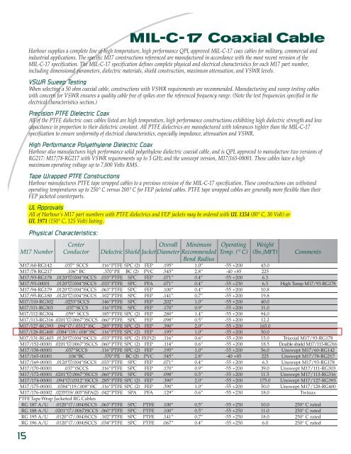
MIL-C-17 <strong>Coaxial</strong> <strong>Cable</strong><br />
<strong>Harbour</strong> supplies a complete line of high temperature, high performance QPL approved MIL-C-17 coax cables for military, commercial and<br />
industrial applications. The specific M17 constructions referenced are manufactured in accordance with the most recent revision of the<br />
MIL-C-17 specification. The MIL-C-17 specification defines complete physical and electrical characteristics for each M17 part number,<br />
including dimensional parameters, dielectric materials, shield construction, maximum attenuation, and VSWR levels.<br />
VSWR Sweep Testing<br />
When selecting a 50 ohm coaxial cable, constructions with VSWR requirements are recommended. Manufacturing and sweep testing cables<br />
with concern for VSWR ensures a quality cable free of spikes over the referenced frequency range. (Note the test frequencies specified in the<br />
electrical characteristics section.)<br />
Precision PTFE Dielectric Coax<br />
All of the PTFE dielectric coax cables listed are high temperature, high performance constructions exhibiting high dielectric strength and low<br />
capacitance in proportion to their dielectric constant. All PTFE dielectrics are manufactured with tolerances tighter than the MIL-C-17<br />
specification to ensure uniformity of electrical characteristics, especially impedance, attenuation and VSWR.<br />
High Performance Polyethylene Dielectric Coax<br />
<strong>Harbour</strong> also manufactures high performance solid polyethylene dielectric coaxial cable, and is QPL approved to manufacture two versions of<br />
<strong>RG</strong>217: M17/78-<strong>RG</strong>217 with VSWR requirements up to 3 GHz and the unswept version, M17/165-00001. These cables have a high<br />
maximum operating voltage up to 7,000 Volts RMS.<br />
Tape Wrapped PTFE Constructions<br />
<strong>Harbour</strong> manufactures PTFE tape wrapped cables to a previous revision of the MIL-C-17 specification. These constructions can withstand<br />
operating temperatures up to 250° C versus 200° C for FEP jacketed cables. PTFE tape wrapped cables are generally more flexible than their<br />
FEP jacketed counterparts.<br />
UL Approvals<br />
All of <strong>Harbour</strong>’s M17 part numbers with PTFE dielectrics and FEP jackets may be ordered with UL 1354 (80° C, 30 Volt) or<br />
UL 1971 (150° C, 125 Volt) listing.<br />
Physical Characteristics:<br />
Center Overall Minimum Operating Weight<br />
M17 Number Conductor Dielectric Shield Jacket Diameter Recommended Temp. (° C) (lbs./MFT) Comments<br />
Bend Radius<br />
M17/60-<strong>RG</strong>142 .037” SCCS .116”PTFE SPC (2) FEP .195” 1.0” -55 +200 43.0<br />
M17/78-<strong>RG</strong>217 .106” BC .370”PE BC (2) PVC .545” 2.8” -40 +85 225<br />
M17/93-<strong>RG</strong>178 .0120”(7/.004”)SCCS .033”PTFE SPC FEP .071” 0.4” -55 +200 6.3<br />
M17/93-00001 .0120”(7/.004”)SCCS .033”PTFE SPC PFA .071” 0.4” -55 +230 6.3 High Temp M17/93-<strong>RG</strong>178<br />
M17/94-<strong>RG</strong>179 .0120”(7/.004”)SCCS .063”PTFE SPC FEP .100” 0.4” -55 +200 10.8<br />
M17/95-<strong>RG</strong>180 .0120”(7/.004”)SCCS .102”PTFE SPC FEP .141” 0.7” -55 +200 19.8<br />
M17/110-<strong>RG</strong>302 .0253”SCCS .146”PTFE SPC FEP .202” 1.0” -55 +200 40.0<br />
M17/111-<strong>RG</strong>303 .037”SCCS .116”PTFE SPC FEP .170” 0.9” -55 +200 31.0<br />
M17/112-<strong>RG</strong>304 .059” SCCS .185”PTFE SPC (2) FEP .280” 1.4” -55 +200 94.0<br />
M17/113-<strong>RG</strong>316 .0201”(7/.0067”)SCCS .060”PTFE SPC FEP .098” 0.5” -55 +200 12.2<br />
M17/127-<strong>RG</strong>393 .094”(7/.0312”)SC .285”PTFE SPC (2) FEP .390” 2.0” -55 +200 165.0<br />
M17/128-<strong>RG</strong><strong>400</strong> .0384”(19/.008”)SC .116”PTFE SPC (2) FEP .195” 1.0” -55 +200 50.0<br />
M17/131-<strong>RG</strong>403 .0120”(7/.004”)SCCS .033”PTFE SPC (2) FEP(2) .116” 0.6” -55 +200 15.0 Triaxial M17/93-<strong>RG</strong>178<br />
M17/152-00001 .0201”(7/.0067”)SCCS .060”PTFE SPC (2) FEP .114” 0.6” -55 +200 18.5 Double shield M17/113-<strong>RG</strong>316<br />
M17/158-00001 .037”SCCS .116”PTFE SPC (2) FEP .195” 1.0” -55 +200 56.0 Unswept M17/60-<strong>RG</strong>142<br />
M17/165-00001 .106”BC .370”PE BC (2) PVC .545” 2.8” -40 +85 225 Unswept M17/78-<strong>RG</strong>217<br />
M17/169-00001 .0120”(7/.004”)SCCS .033”PTFE SPC FEP .071” 0.4” -55 +200 6.3 Unswept M17/93-<strong>RG</strong>178<br />
M17/170-00001 .037”(SCCS .116”PTFE SPC FEP .170” 0.9” -55 +200 39.0 Unswept M17/111-<strong>RG</strong>303<br />
M17/172-00001 .0201”(7/.0067”)SCCS .060”PTFE SPC FEP .098” 0.5” -55 +200 11.5 Unswept M17/113-<strong>RG</strong>316<br />
M17/174-00001 .094”(7/.0312”)SCCS .285”PTFE SPC (2) FEP .390” 2.0” -55 +200 175.0 Unswept M17/127-<strong>RG</strong>393<br />
M17/175-00001 .0384”(19/.008”)SC .116”PTFE SPC (2) FEP .390” 1.0” -55 +200 50.0 Unswept M17/128-<strong>RG</strong><strong>400</strong><br />
M17/176-00002 .0235”(19/.005”)SPA(2) .042”PTFE SPA PFA .129” 0.6” -55 +230 18.0 Twinax<br />
PTFETapeWrap Jacketed <strong>RG</strong> <strong>Cable</strong>s<br />
<strong>RG</strong> 187 A/U .0120”(7/.004)SCCS .063”PTFE SPC PTFE .100” 0.5” -55 +250 10.0 250° C rated<br />
<strong>RG</strong> 188 A/U .0201”(7/.0067)SCCS .060”PTFE SPC PTFE .100” 0.5” -55 +250 11.0 250° C rated<br />
<strong>RG</strong> 195 A/U .0120”(7/.004)SCCS .102”PTFE SPC PTFE .141” 0.7” -55 +250 18.0 250° C rated<br />
<strong>RG</strong> 196 A/U .0120”(7/.004)SCCS .034”PTFE SPC PTFE .067” 0.4” -55 +250 6.0 250° C rated
MIL-C-17 <strong>Coaxial</strong> <strong>Cable</strong><br />
QPL Approved<br />
Single braid<br />
Double braid<br />
Triax<br />
Twinax<br />
Electrical Characteristics:<br />
Attenuation (dB/100ft) @<br />
M17 Number Impedance Capacitance Max Voltage 100 MHz <strong>400</strong> MHz 1 GHz 2.4 GHz 5 GHz 10 GHz<br />
(ohms) (pF/ft) Typ / Max Typ / Max Typ / Max Typ / Max Typ / Max Typ / Max<br />
Max Frequency<br />
(GHz)<br />
M17/60-<strong>RG</strong>142 50 +/- 2 29.4 1900 4.0 / 5.5 8.1 / 11.7 13.4 / 19.2 21.3 / 30.4 33.3 / 48.7 - 17.4<br />
M17/76-<strong>RG</strong>217 50 +/- 2 30.8 7000 1.5 / 1.6 3.5 / 3.7 6.7 / 7.0 - - - 3.0<br />
M17/93-<strong>RG</strong>178 50 +/- 2 29.4 1000 13.0 / 16.0 27.2 / 33.0 44.2 / 52.0 41.7 / 56.1 - - 3.0<br />
M17/93-00001 50 +/- 2 29.4 1000 13.0 / 16.0 27.2 / 33.0 44.2 / 52.0 41.7 / 56.1 - - 3.0<br />
M17/94-<strong>RG</strong>179 75 +/- 3 19.4 1200 8.0 / 9.2 15.5 / 21.0 26.7 / 30.7 - - - -<br />
M17/95-<strong>RG</strong>180 95 +/- 5 17.4 1500 5.7 / 6.6 11.7 / 17.4 19.2 / 23.0 - - - -<br />
M17/110-<strong>RG</strong>302 75 +/- 3 19.4 2300 - 7.2 / 8.0 - - - - -<br />
M17/111-<strong>RG</strong>303 50 +/- 2 29.4 1900 3.5 / 3.9 7.2 / 8.0 13.5 / 15.0 - - - -<br />
M17/112-<strong>RG</strong>304 50 +/- 2 29.4 3000 2.4 / 2.7 5.8 / 6.4 10.0 / 11.1 - - - 8.0<br />
M17/113-<strong>RG</strong>316 50 +/- 2 29.4 1200 7.6 / 11.0 16.0 / 21.0 26.2 / 38.0 41.2 / 55.4 - - 3.0<br />
M17/127-<strong>RG</strong>393 50 +/- 2 29.4 2500 2.3 / 2.5 4.4 / 5.0 7.7 / 9.2 12.4 / 14.2 21.3 / 26.8 30.1 / 37.9 11.0<br />
M17/128-<strong>RG</strong><strong>400</strong> 50 +/- 2 29.4 1900 4.3 / 4.5 8.6 / 10.5 14.1 / 18.1 22.6 / 30.2 35.6 / 52.1 61.6 / 78.0 12.4<br />
M17/131-<strong>RG</strong>403 50 +/- 2 29.4 1000 - 33.3 / 37.0 - - - - 10.0<br />
M17/152-00001 50 +/- 2 29.4 1200 8.1 / 11.5 17.8 / 24.0 29.6 / 40.0 43.1 / 58.3 100.0 /110.0 153.0 /170.0 12.4<br />
M17/158-00001 50 +/- 2 29.4 1900 - 8.1 / 9.5 - - - -<br />
M17/165-00001 50 +/- 2 29.4 7000 - 3.5 / 3.7 - - - -<br />
M17/169-00001 50 +/- 2 29.4 1000 - 27.2 / 29.0 - - - - -<br />
M17/170-00001 50 +/- 2 29.4 1900 - 7.7 / 8.6 - - - - -<br />
M17/172-00001 50 +/- 2 29.4 1200 - 15.5 / 21.0 - - - - -<br />
M17/174-00001 50 +/- 2 29.4 2500 - 4.4 / 5.0 - - - - -<br />
M17/175-00001 50 +/- 2 29.4 1900 - 8.6 /10.5 - - - - -<br />
M17/176-00001 77 +/- 7 19.0 1000 - - - - - - -<br />
PTFE Tape Wrap Jacketed <strong>RG</strong> <strong>Cable</strong>s<br />
<strong>RG</strong> 187 A/U 75 +/- 3 19.4 1200 - 15.5 / 21.0 - - - -<br />
<strong>RG</strong> 188 A/U 50 +/- 2 29.4 1200 7.6 / 11.0 16.0 / 21.0 26.2 / 38.0 41.2 / 55.4 - - 3.0<br />
<strong>RG</strong> 195 A/U 95 +/- 5 17.4 1500 - 11.7 / 17.4 - - - -<br />
<strong>RG</strong> 196 A/U 50 +/- 2 29.4 1000 13.0 / 16.0 27.2 / 33.0 44.2 / 52.0 41.7 / 56.1 - - 3.0<br />
“Maximum frequencies” are those as referenced on individual slant sheets of the MIL-C-17 specification. No values are given for unswept constructions<br />
as the specification recommends these cables should not be used above <strong>400</strong> MHz. All figures referenced above are nominal unless otherwise specified.<br />
16
MIL-C-17 <strong>Coaxial</strong> <strong>Cable</strong>s<br />
- including M17/176-00001 Twinaxial Data Bus <strong>Cable</strong><br />
<strong>Harbour</strong> Industries is a QPL approved manufacturer of high temperature, high performance coaxial cables supplied<br />
in exact accordance with the MIL-C-17 specification. The information referenced has been taken from the MIL-C-17<br />
“slant sheets” which define complete physical and electrical characteristics for each MIL-C-17 part number including<br />
dimensional parameters, dielectric materials, shield constructions, VSWR, and maximum attenuation over various<br />
frequency ranges. For complete individual slant sheets, see the Defense Supply Center Columbus (DSCC) link in the<br />
Industry Links section of <strong>Harbour</strong>’s website.<br />
The Importance of VSWR Sweep Testing<br />
When selecting a 50 ohm coaxial cable, constructions with VSWR requirements are highly recommended.<br />
Manufacturing and sweep testing cables with concern for VSWR ensures a quality cable free of spikes over the<br />
frequency range referenced on the slant sheet.<br />
Precision PTFE Dielectrics Used<br />
All of the PTFE dielectric coax cables listed are high temperature, high performance constructions exhibiting high<br />
dielectric strength and low capacitance in proportion to the cable’s dielectric constant. <strong>Harbour</strong> manufactures all PTFE<br />
dielectric cable constructions with tolerances tighter than the MIL-C-17 specification to ensure uniformity of electrical<br />
characteristics, especially impedance, attenuation, and VSWR.<br />
Constructions with PTFE Tape Wrapped Jackets<br />
<strong>Harbour</strong> manufactures PTFE tape wrapped cables - specifically <strong>RG</strong>187 A/U, <strong>RG</strong>188 A/U, <strong>RG</strong>195 A/U, and <strong>RG</strong>196 A/U<br />
- in accordance with a previous revision of the MIL-C-17 specification. These constructions can withstand operating<br />
temperatures up to 250 º versus 200º C for FEP jacketed cables. PTFE tape wrapped cables are generally more flexible<br />
than their FEP jacketed counterpart. Alternative 250º constructions are also available with PFA jackets.<br />
M17 Part<br />
Center Dielectric<br />
Shield<br />
Overall Bend Weight Comments<br />
Conductor Diameter Shield Diameter Jacket Diameter Radius (lbs/mft)<br />
M17/60-<strong>RG</strong>142 .037” SCCS .116” SPC (2) .160" FEP .195” 1.0” 43.0<br />
M17/93-<strong>RG</strong>178 .0120” (7/.004”)SCCS .033” SPC .051" FEP .071” 0.4” 6.3<br />
M17/94-<strong>RG</strong>179 .0120” (7/.004”)SCCS .063” SPC .080" FEP .100” 0.4” 10.8<br />
M17/95-<strong>RG</strong>180 .0120” (7/.004”)SCCS .102” SPC .118" FEP .141” 0.7” 19.8<br />
M17/111-<strong>RG</strong>303 .037” SCCS .116” SPC .136" FEP .170” 0.9” 31.0<br />
M17/112-<strong>RG</strong>304 .059” SCCS .185” SPC (2) .240" FEP .280” 1.4” 94.0<br />
M17/113-<strong>RG</strong>316 .0201” (7/.0067”)SCCS .060” SPC .075" FEP .098” 0.5” 12.2<br />
M17/127-<strong>RG</strong>393 .094” (7/.0312”) SPC .285” SPC (2) .314" FEP .390” 2.0” 165.0<br />
M17/128-<strong>RG</strong><strong>400</strong> .0384” (19/.008”) SPC .116” SPC (2) .156" FEP .195” 1.0” 50.0<br />
M17/131-<strong>RG</strong>403 .0120” (7/.004”)SCCS .033” SPC (2) .090" FEP (2) .116” 0.6” 15.0 Triaxial <strong>RG</strong>-178<br />
M17/152-00001 .0201” (7/.0067”)SCCS .060” SPC (2) .091" FEP .114” 0.6” 18.5 Double Shield <strong>RG</strong>-316<br />
M17/158-00001** .037” SCCS .116” SPC (2) .160" FEP .195” 1.0” 56.0 Use M17/60-<strong>RG</strong>142<br />
M17/169-00001** .0120” (7/.004”)SCCS .033” SPC .051" FEP .071” 0.4” 6.3 Use M17/93-<strong>RG</strong>178<br />
M17/170-00001** .037” SCCS .116” SPC .136" FEP .170” 0.9” 39.0 Use M17/111-<strong>RG</strong>303<br />
M17/172-00001** .0120” (7/.004”)SCCS .060” SPC .075" FEP .098” 0.5” 11.5 Use M17/113-<strong>RG</strong>316<br />
M17/175-00001** .0384”(19/.008”)SPC .116” SPC (2) .156" FEP .195” 1.0” 50.0 Use M17/128-<strong>RG</strong><strong>400</strong><br />
M17/176-00002 .0235” (19/.005”)SPA(2) .042” SPA .100" PFA .129” 0.6” 18.0 Twinax<br />
<strong>RG</strong>187 A/U .0120” (7/.004”)SCCS .063” SPC .079" PTFE .100” 0.5” 10.0 Tape Wrapped Jacket<br />
<strong>RG</strong>188 A/U .0201” (7/.0067”)SCCS .060” SPC .080" PTFE .100” 0.5” 11.0 Tape Wrapped Jacket<br />
<strong>RG</strong>195 A/U .0129” (7/.004”)SCCS .102” SPC .117" PTFE .141” 0.7” 18.0 Tape Wrapped Jacket<br />
<strong>RG</strong>196 A/U .0120” (7/.004”)SCCS .034” SPC .050" PTFE .067” 0.4” 6.0 Tape Wrapped Jacket<br />
** DSCC has removed these part numbers from MIL-DTL-17.<br />
<strong>Harbour</strong> Industries • 4744 Shelburne Road • Shelburne • Vermont • 05482 • USA • 802-985-3311