IAQ Surveyor Manual - Equipco
IAQ Surveyor Manual - Equipco
IAQ Surveyor Manual - Equipco

You also want an ePaper? Increase the reach of your titles
YUMPU automatically turns print PDFs into web optimized ePapers that Google loves.
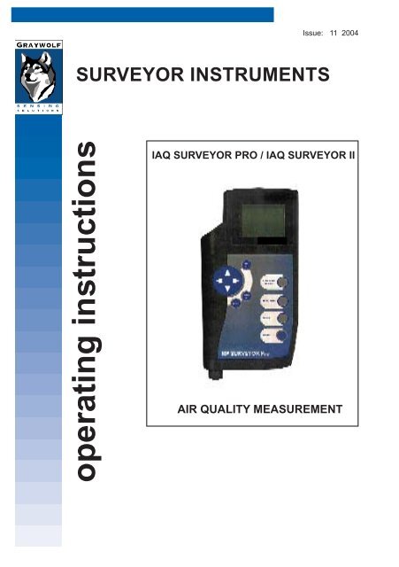
Issue: 11 2004<br />
SURVEYOR INSTRUMENTS<br />
operating instructions<br />
<strong>IAQ</strong> SURVEYOR PRO / <strong>IAQ</strong> SURVEYOR II<br />
AIR QUALITY MEASUREMENT
MAN <strong>IAQ</strong> <strong>Surveyor</strong> Issue 11 2004<br />
2
MAN <strong>IAQ</strong> <strong>Surveyor</strong> Issue 11 2004<br />
HELP US TO HELP YOU<br />
Every effort has been made to ensure the accuracy in the<br />
contents of our documents, however, GratWolf Sensing<br />
Solutions, LTD can assume no responsibility for any errors or<br />
omissions in our documents or their consequences.<br />
GrayWolf would greatly appreciate being informed of any<br />
errors or omissions that may be found in the contents of any<br />
of our documents and to this end we include the following<br />
form for you to photocopy, complete and return to us so that<br />
we may take the appropriate action.<br />
3
MAN <strong>IAQ</strong> <strong>Surveyor</strong> Issue 11 2004<br />
HELP US TO HELP YOU<br />
To:<br />
Marketing Communications,<br />
GrayWolf Sensing Solutions<br />
12 Cambridge Dr.<br />
Trumbull, CT 06611<br />
From :<br />
Address :<br />
Tel : 203-416-0005<br />
Fax : 203-416-0002<br />
email : <strong>Manual</strong>s@WolfSense.com<br />
Tel :<br />
Fax :<br />
email :<br />
I suggest the following corrections/changes be made to Section ...........<br />
Marked up copies attached (as appropriate):<br />
Yes / No<br />
Please inform me of the outcome of this change: Yes / No<br />
For Marketing Communications, GrayWolf:<br />
Actioned By:<br />
Response:<br />
Date:<br />
Date:<br />
4
MAN <strong>IAQ</strong> <strong>Surveyor</strong> Issue 11 2004<br />
COPYRIGHT AND WARRANTY<br />
COPYRIGHT<br />
This publication contains information partly derived from<br />
proprietary data of GrayWolf. The express purpose of this<br />
information is to assist in the operation and maintenance of the<br />
instrument described herein. The publication of this information<br />
does not convey any right to reproduce or use the information for<br />
any purpose other than in the operation or maintenance of the<br />
equipment described herein.<br />
GrayWolf shall not be liable for any incidental or consequential<br />
damages in connection with any deletions, errors or omissions in<br />
this <strong>Manual</strong>.<br />
PRODUCT WARNING<br />
GrayWolf Sensing Solutions' <strong>IAQ</strong> <strong>Surveyor</strong> instruments are<br />
NOT suitable for use in fl ammable or potentially explosive<br />
environments. They are NOT certifi ed intrinsically safe. They are<br />
also NOT intended for use in confi ned spaces where operator<br />
safety might be at risk due to exposure levels, such as reduced<br />
oxygen, during the course of the instrument survey.<br />
WARRANTY<br />
GrayWolf warrants each SURVEYOR instrument to be free from<br />
any defects in workmanship, materials and components for one<br />
year from the date of purchase. Any SURVEYOR instrument<br />
found to be defective by GrayWolf within the warranty period<br />
will be repaired (or replaced at GrayWolf's discretion), providing<br />
that the product is returned, shipping prepaid, to GrayWolf or an<br />
authorized GrayWolf distributor.<br />
SURVEYOR instrument failure must not have occurred as a<br />
result of operation of the instrument other than in accordance<br />
with the instructions furnished with the instrument.<br />
This warranty does not apply if the instrument has been<br />
subjected to unusual physical or electrical stress or on which the<br />
original identifi cation marks have been removed or altered.<br />
5
MAN <strong>IAQ</strong> <strong>Surveyor</strong> Issue 11 2004<br />
COPYRIGHT AND WARRANTY<br />
This warranty will not apply if adjustments, repair or parts replacement<br />
is required because of accident, hazard, misuse, transportation or<br />
causes other then ordinary use; in which case<br />
repair will be charged at normal rates. An estimate will be submitted<br />
before repair work starts and a purchase order must be supplied<br />
before work begins. Any out of warranty repairs are warranted 90<br />
days from the date of invoice. The warranty does not apply if any<br />
modifications have been made by anyone other than GrayWolf or an<br />
authorized distributor.<br />
The foregoing warranty is in lieu of all other warranties, conditions,<br />
terms, undertakings and obligations implied by statute, common law,<br />
custom, trade usage, course of dealing, or otherwise, all of which<br />
are hereby excluded to the fullest extent permitted by law. This<br />
warranty does not affect the statutory rights of a consumer. In such<br />
transactions, the rights and obligations of the Buyer and Seller shall<br />
be determined by statute.<br />
GrayWolf shall have no liability or obligations under this warranty<br />
other than to remedy breaches thereof by the provision of materials<br />
and services within a reasonable time and without charge (or,<br />
where appropriate In accordance with the above at normal rates).<br />
If GrayWolf shall fail to comply with such obligations its liability for<br />
such failure shall be limited to a sum equal to the price. The foregoing<br />
states the entire liability of GrayWolf, whether in contract or in tort,<br />
for defects in the instrument notifi ed to it after the date of purchase<br />
order other than liability arising where loss of damage to any property<br />
or injury to or death of any person is caused by any negligent act or<br />
omissions or wilful misconduct of GrayWolf, its employees, agents or<br />
subcontractors or by any defect in the design or workmanship of the<br />
instrument.<br />
Save as otherwise stated, in no circumstances shall GrayWolf be<br />
liable in contract or in tort or otherwise for any direct incidental or<br />
consequential loss suffered by the purchaser or their agents.<br />
GrayWolf does not give any warranty that the instrument is fi t for<br />
any particular purpose unless the purpose is specifi cally advised<br />
to GrayWolf in writing and GrayWolf confi rms in writing that the<br />
instrument can fulfi l that particular purpose. Representations and<br />
warranties which are inconsistent with the terns of this warranty<br />
are not valid unless approved in writing by an offi cer of GrayWolf .<br />
Contact GrayWolf directly if there are any questions about this<br />
warranty.<br />
6
MAN <strong>IAQ</strong> <strong>Surveyor</strong> Issue 11 2004<br />
TWENTY SHORT-CUTS<br />
The following may be of help as a quick reference:<br />
How do I You should: Or<br />
(then press MENU/METER to Refer To<br />
return to the Measurement screen) Section:<br />
1 Change the units Press MENU/METER; 2.4.3.1<br />
of measurement for select Channel Setup;<br />
one of the sensors. select sensor to change;<br />
(not available for select Select Units;<br />
all sensors). select new units;<br />
. press ACCEPT.<br />
2 Find out when a Press MENU/METER; 2.4.3.5<br />
sensor was last select Channel Setup;<br />
calibrated.<br />
select sensor;<br />
select Channel Info.<br />
3 Calibrate a sensor. Press MENU/METER; 6.1<br />
(Not available for select Channel Setup;<br />
all sensors) select sensor;<br />
select Calibrate Sensor.<br />
Select Do Standard Low Cal;<br />
calibrate; press ACCEPT.<br />
Select Do Standard High Cal;<br />
calibrate; press ACCEPT.<br />
4 Revert to the factory Press MENU/METER; 6.3.3<br />
calibration settings select Channel Setup;<br />
for a sensor. select sensor;<br />
select Calibrate Sensor;<br />
select Clear Cal;<br />
press ACCEPT.<br />
`<br />
5 Display the Press MENU/METER; 2.5.1<br />
min/max/average press ACCEPT;<br />
values.<br />
press left/right arrows to show all<br />
available data.<br />
7
MAN <strong>IAQ</strong> <strong>Surveyor</strong> Issue 11 2004<br />
TWENTY SHORT-CUTS<br />
How do I You should: Or<br />
(then press MENU/METER to Refer To<br />
return to the Measurement screen) Section:<br />
6 Reset the Press MENU/METER; 2.5.3<br />
min/max/average select Clear Min/Max/Avg;<br />
calculations. press ACCEPT.<br />
7 Change the name Press MENU/METER; 4.2.2<br />
of a Site/Location. select Data Logging;<br />
select Rename Site/Loc;<br />
use alphanumeric screen to<br />
rename;<br />
press ACCEPT.<br />
8 Change the default Press MENU/METER; 4.2.4<br />
Site/Location. select Data Logging;<br />
press ACCEPT;<br />
select new Site/Location;<br />
press ACCEPT.<br />
9 Change the default Press MENU/METER; 4.3.5<br />
logging interval. select Data Logging;<br />
select Log Timing;<br />
change timing;<br />
press ACCEPT.<br />
10 Set the instrument Press MENU/METER; 4.3.4<br />
to log overnight. select Data Logging;<br />
select Log Timing;<br />
change Auto St. to ON;<br />
set start time/date;<br />
set fi nish time/date;<br />
press ACCEPT<br />
8
MAN <strong>IAQ</strong> <strong>Surveyor</strong> Issue 11 2004<br />
TWENTY SHORT-CUTS<br />
How do I You should: Or<br />
(then press MENU/METER to Refer To<br />
return to the Measurement screen) Section:<br />
11 Find out how much Press MENU/METER; 2.2.3<br />
log memory remains. select Instrument Info;<br />
press ACCEPT.<br />
12 View the log data Press MENU/METER; 4.4.2<br />
that is stored in the select Data Logging;<br />
instrument. select View Log Data;<br />
select Site/Location;<br />
select session to view;<br />
limit data to be viewed;<br />
press ACCEPT.<br />
13 Print the log data Press MENU/METER; 4.4.4<br />
that is stored in the select Data Logging;<br />
instrument. select Print Logged Data;<br />
select Site/Location;<br />
press ACCEPT;<br />
select session;<br />
limit data to be printed;<br />
press ACCEPT.<br />
14 Display the battery Press MENU/METER; 2.2.3<br />
remaining life select Instrument Info,<br />
percentage press ACCEPT<br />
15 Lock the keypad. Press MENU/METER; 2.3.3.4<br />
select Instrument Setup;<br />
select Lock Keypad;<br />
press ACCEPT.<br />
16 Unlock the keypad. Press the cursor left and right 2.3.3.4<br />
arrows at the same time.<br />
9
MAN <strong>IAQ</strong> <strong>Surveyor</strong> Issue 11 2004<br />
TWENTY SHORT-CUTS<br />
How do I You should: Or<br />
(then press MENU/METER to Refer To<br />
return to the Measurement screen) Section:<br />
17 Switch on/off the Press MENU/METER; 2.3.3.1<br />
alarm or keypad select Instrument Setup;<br />
bleep.<br />
press ACCEPT;<br />
press right arrow;<br />
press up for On or down for Off;<br />
press ACCEPT.<br />
18 Change the alarm Press MENU/METER; 2.4.4<br />
levels for one of the select Channel Setup;<br />
sensors.<br />
select sensor to change;<br />
select Set Alarms;<br />
change alarm level;<br />
press ACCEPT.<br />
19 Display the serial Press MENU/METER; 2.2.3<br />
number of a probe. select Instrument Info;<br />
press ACCEPT<br />
20 Switch off one of the Press MENU/METER; 2.4.3.4<br />
sensors.<br />
select Channel Setup;<br />
select sensor to switch off;<br />
select Disable Channel;<br />
press ACCEPT.<br />
10
MAN <strong>IAQ</strong> <strong>Surveyor</strong> Issue 11 2004<br />
CONTENTS<br />
Section<br />
Page<br />
Twenty Short-cuts 7<br />
1. INTRODUCTION 17<br />
1.1 Introduction 17<br />
1.2 Main Features 18<br />
1.2.1 <strong>IAQ</strong> <strong>Surveyor</strong> Pro 18<br />
1.2.2 <strong>IAQ</strong> <strong>Surveyor</strong> II 18<br />
1.3 Power Supplies 19<br />
1.4 Battery Life 20<br />
1.5 Probe Connections 20<br />
1.6 Connecting Auxiliary Equipment 21<br />
1.7 Keypad Functions 22<br />
1.8 Modes of Operation 24<br />
1.8.1 General 24<br />
1.8.2 Meter Mode 25<br />
1.8.3 Menu Mode 26<br />
2. USING THE INSTRUMENTS 27<br />
2.1 Getting Started 27<br />
2.2 Using the Instrument Information Facility 28<br />
2.2.1 General 28<br />
2.2.2 Getting to the Instrument Info Screen 28<br />
2.2.3 Details on the Instrument Info screen 29<br />
2.3 Using the Instrument Setup Facility 31<br />
2.3.1 General 31<br />
2.3.2 Getting to the Instrument Setup screen 32<br />
2.3.3 Using the Instrument Setup Options 32<br />
11
MAN <strong>IAQ</strong> <strong>Surveyor</strong> Issue 11 2004<br />
CONTENTS<br />
Section<br />
Page<br />
2.4 Using the Channel Setup Facility 36<br />
2.4.1 General 36<br />
2.4.2 Getting to a Channel Setup Screen 36<br />
2.4.3 Using the Channel Setup Options 37<br />
2.4.4 Changing the Alarm Limits 39<br />
2.4.5 Displayed Channel Information 40<br />
2.5 Using the Min/Max/Average Facility 41<br />
2.5.1 General 41<br />
2.5.2 Viewing the Mm/Max/Average Values 42<br />
2.5.3 Resetting the Mm/Max/Average Values 43<br />
3. MICROMANOMETER AND THERMOCOUPLE 45<br />
3.1 General 45<br />
3.2 Thermocouple 45<br />
3.3 Micromanometer 45<br />
3.3.1 General 45<br />
3.3.2 Pressure Measurements 46<br />
3.3.3 Autozero Facility 47<br />
3.3.4 Pressure Connections 47<br />
3.3.5 Volume Flow Rate 48<br />
3.3.6 Duct Averaging - Storing Readings 50<br />
3.3.7 Duct Averaging - Viewing Readings 50<br />
4. DATALOGGING FACILITIES 53<br />
4.1 General 53<br />
4.2 Confi guring the Site/Location References 53<br />
4.2.1 General 53<br />
4.2.2 Changing an Existing Site or Location 53<br />
Reference<br />
4.2.3 Adding a New Site or Location Reference 54<br />
4.2.4 Changing the Default Site/Location Reference 55<br />
4.2.5 Deleting a Site or Location 55<br />
4.2.6 Navigating to a Site and Location 56<br />
4.2.7 Using the Alphanumeric Selection Screen 57<br />
12
MAN <strong>IAQ</strong> <strong>Surveyor</strong> Issue 11 2004<br />
CONTENTS<br />
Section<br />
Page<br />
4.3 Logging the Environmental Conditions 58<br />
4.3.1 General 58<br />
4.3.2 Storing Individual Probe Measurements 59<br />
4.3.3 Logging Continuously 59<br />
4.3.4 Using the Data Logging Autostart Facility 60<br />
4.3.5 Setting the Default Logging Interval 63<br />
4.4 Accessing the Logged Data 64<br />
4.4.1 General 64<br />
4.4.2 Viewing Logged Data 65<br />
4.4.3 Deleting Logged Data 66<br />
4.4.4 Printing Logged Data 68<br />
5. PC SOFTWARE 71<br />
5.1 General 71<br />
6. CALIBRATION PROCEDURES 73<br />
6.1 Introduction 73<br />
6.2 Using the Quick Cal Facility 73<br />
6.3 Changing the Calibration Levels 74<br />
6.3.1 General 74<br />
6.3.2 Setting New Calibration Levels 75<br />
6.3.3 Reverting to the Factory Settings 76<br />
7. MAINTENANCE PROCEDURES 77<br />
7.1 Introduction 77<br />
7.2 Preventive Maintenance 77<br />
7.3 Battery Maintenance 77<br />
7.3.1 Dry Cell Batteries 77<br />
7.3.2 Rechargeable Batteries 78<br />
7.4 Troubleshooting 78<br />
7.5 Service 78<br />
13
MAN <strong>IAQ</strong> <strong>Surveyor</strong> Issue 11 2004<br />
CONTENTS<br />
Section<br />
Page<br />
8. SPECIFICATION 85<br />
8.1 Dimensions and Weight 85<br />
8.2 Display 85<br />
8.3 Serial Interface (Printer) 85<br />
8.4 Housing 85<br />
8.5 Battery Lifetime at 20 o C 85<br />
8.6 Environmental 86<br />
8.7 Electromagnetic Compatibility (EMC) 86<br />
8.8 Measurement Ranges 87<br />
9. PROBES AND ACCESSORIES 89<br />
9.1 GrayWolf Probes Available for use with the 89<br />
<strong>Surveyor</strong> instruments<br />
9.2 GrayWolf Accessories Available for use with the 90<br />
<strong>Surveyor</strong> instruments<br />
10. PITOT STATIC TUBES AND ACCESSORIES 91<br />
10.1 GrayWolf Pitot Static Tubes 91<br />
10.2 Specifi cations 92<br />
10.2.1 Nose and Head Section 92<br />
10.2.2 Flexible Tubes Types 50-4, 229MS-EXT, 92<br />
10.2.3 Rigid Tubes Types 229MS, 229MM, 299ML 92<br />
10.2.4 Dimensions and Weight (Type 50-4) 92<br />
14
MAN <strong>IAQ</strong> <strong>Surveyor</strong> Issue 11 2004<br />
CONTENTS<br />
FIGURES<br />
Figures<br />
Page<br />
1 <strong>Surveyor</strong> Instruments 17<br />
TABLES<br />
Table<br />
Page<br />
1 Instrument Display Ranges 49<br />
2 Basic Problems and Suggested Remedies 80<br />
3 Summary of the Warning Messages 82<br />
APPENDICES<br />
A Glossary of Terms and Abbreviations 95<br />
B Useful Conversions 99<br />
15
MAN <strong>IAQ</strong> <strong>Surveyor</strong> Issue 11 2004<br />
16
MAN <strong>IAQ</strong> <strong>Surveyor</strong> Issue 11 2004<br />
1. INTRODUCTION<br />
1.1 INTRODUCTION<br />
The <strong>IAQ</strong> <strong>Surveyor</strong> Pro and <strong>IAQ</strong> <strong>Surveyor</strong> II (Figure 1) are two<br />
instruments capable of measuring a variety of air parameters.<br />
These parameters include airspeed, temperature, relative<br />
humidity, CO, CO 2<br />
, etc depending on the type of probe<br />
connected to the instrument. It should be noted that certain<br />
probes will only operate with the <strong>IAQ</strong> <strong>Surveyor</strong> Pro. Up to<br />
four measured parameters are continuously displayed on<br />
the instrument's large graphics display and these readings<br />
may be stored internally. A maximum of 16 parameters are<br />
available depending upon the type of probes fi tted to the<br />
instrument.<br />
The instruments can be used for hand held walk through<br />
surveys or set up to periodically log readings which can later<br />
be downloaded to a PC for further analysis.<br />
This manual covers both instruments and therefore some<br />
features listed may not be available on the <strong>Surveyor</strong> II.<br />
Accessories<br />
Thermocouple<br />
Connecting Point.<br />
Socket Pressure Ports<br />
For PC, Printer or an<br />
(<strong>Surveyor</strong> Pro (<strong>Surveyor</strong> Pro only)<br />
external ac supply.<br />
only)<br />
Liquid Crystal<br />
Display<br />
Simple to<br />
use Keypad<br />
-<br />
+<br />
Start/Stop Average<br />
Datalog.<br />
Battery<br />
Compartment<br />
Probe<br />
Connections<br />
Probe Mounting.<br />
Showing one of the<br />
probes available.<br />
Figure 1 <strong>Surveyor</strong> Instruments<br />
17
MAN <strong>IAQ</strong> <strong>Surveyor</strong> Issue 11 2004<br />
1. INTRODUCTION<br />
1.2 MAIN FEATURES<br />
1.2.1 <strong>IAQ</strong> <strong>Surveyor</strong> Pro<br />
a. Auto data logging with log download to PC.<br />
b. Two smart probe sockets.<br />
c. Supports all types of smart probe.<br />
d. Supplied with 1260GSS <strong>IAQ</strong> Multi-parameter probe<br />
as standard.<br />
e. Built-in micromanometer and Type k thermocouple<br />
socket.<br />
f. Duct Averaging facility.<br />
1.2.2 <strong>IAQ</strong> <strong>Surveyor</strong> II<br />
a. Auto data logging with log download to PC.<br />
b. Two smart probe sockets.<br />
c. Supports all types of smart probe.<br />
d. Supplied with 1260GSS <strong>IAQ</strong> Multi-parameter probe<br />
as standard.<br />
18
MAN <strong>IAQ</strong> <strong>Surveyor</strong> Issue 11 2004<br />
1. INTRODUCTION<br />
1.3 POWER SUPPLIES<br />
Power supplies for the instruments may be:<br />
a. Three alkaline dry cells.<br />
Duracell MN1400 LR 14 types are recommended.<br />
b. Three rechargeable cells.<br />
Nickel Cadmium, Nickel Metal Hydride (NiMH) or<br />
Lithium Ion (Li Ion).<br />
Note: Alkaline dry cell batteries are used for battery life<br />
indications these indications are not valid with any<br />
other type of<br />
battery.<br />
Insert the three<br />
batteries, positive<br />
terminal fi rst, into the<br />
battery compartment<br />
and securely tighten the battery end cap.<br />
Rechargeable batteries must be removed from the instrument<br />
and recharged externally using a proprietary battery charger.<br />
Alternatively the instrument may be operated from an<br />
external GrayWolf AC Adaptor operating from a 110/240 V<br />
ac supply.<br />
Note: When the adaptor is plugged into the instrument the<br />
internal batteries are automatically disconnected.<br />
There is therefore no need to remove the batteries<br />
from the instrument when an ac adaptor is being<br />
19
MAN <strong>IAQ</strong> <strong>Surveyor</strong> Issue 11 2004<br />
1. INTRODUCTION<br />
used.<br />
1.4 BATTERY LIFE<br />
Approximately 30 hours:<br />
Using a1260GSS <strong>IAQ</strong> Multiparameter<br />
probe<br />
Approximately 170 hours: Using a 2300AHTS Multiparameter<br />
probe (assumes zero<br />
air speed)<br />
1.5 PROBE CONNECTIONS<br />
Both versions of the instrument may operate two smart<br />
probes simultaneously. Probes are connected to sockets<br />
located at the bottom of the instrument as shown below:<br />
Two 8 way connectors<br />
suitable for all probes<br />
Location of the Probe Connectors<br />
When connecting a probe ensure that the locating peg on<br />
the probe plug is aligned with the corresponding slot in the<br />
socket. Push the plug fi rmly into the socket and carefully<br />
screw the plug collar into the security ring.<br />
With the exception of the <strong>IAQ</strong> <strong>Surveyor</strong> II, an additional<br />
external temperature measurement can be made using a<br />
suitable thermocouple connected to the k type socket on the<br />
top of the instrument.<br />
Two ports on the top of the instrument allow the connection<br />
of tubing for the measurement of differential pressure<br />
(micromanometry).<br />
20
MAN <strong>IAQ</strong> <strong>Surveyor</strong> Issue 11 2004<br />
1. INTRODUCTION<br />
1.6 CONNECTING AUXILIARY EQUIPMENT<br />
Both instruments are fi tted with an accessories socket on the<br />
top left of the instrument as shown below:<br />
7 Way Accessories<br />
Connector<br />
Individual<br />
Cables<br />
PC Cable<br />
Printer Cable<br />
AC Adaptor<br />
Accessories Connector<br />
Y Adaptor<br />
Connect to PC<br />
Connect to ac Adaptor<br />
The following equipment may be connected to the<br />
accessories socket:<br />
a. An ac adaptor.<br />
b. Equipment such as a PC or printer.<br />
The GrayWolf ACC-ADY125-CL Y adaptor may be used<br />
when connecting both the ac adaptor supply and the external<br />
equipment to the instrument.<br />
21
MAN <strong>IAQ</strong> <strong>Surveyor</strong> Issue 11 2004<br />
1. INTRODUCTION<br />
1.7 KEYPAD FUNCTIONS<br />
The instrument operation is controlled from an easy to use<br />
keypad which includes a four way cursor key for selecting<br />
sub menus. The keypad functions are shown below:<br />
When the instrument is switched on, the display will briefl y<br />
LOG/F1<br />
STORE/F2<br />
START/STOP<br />
Press to initiate<br />
Press to store the displayed AVERAGE<br />
Continuous Logging. measurement. (F2 refers to Press to initiate START/<br />
(F1 refers to menu menu functions only)<br />
STOP duct averaging using<br />
functions only)<br />
the STORE/F2 key<br />
(<strong>IAQ</strong> <strong>Surveyor</strong> Pro only)<br />
4 Way Cursor Key<br />
Press the appropriate<br />
arrow to move to other<br />
information.<br />
MENU/METER<br />
Toggles between<br />
METER mode and<br />
MENU mode.<br />
CANCEL<br />
Used to abort menu<br />
selections.<br />
ACCEPT<br />
Used in conjuction with<br />
the menu selections.<br />
(ie. to accept site and<br />
locations).<br />
Keypad<br />
show the time and date. Shortly afterwards and if a probe is<br />
connected, the display will show readings from the probe with<br />
the selected units. Some sensors need time to stabilize when<br />
fi rst switched on and during this time the display will show<br />
three arrows until the probe has stabilized. The thermocouple<br />
channel will display 3 arrows until a thermocouple probe is<br />
connected (not <strong>Surveyor</strong> II). If the <strong>IAQ</strong> <strong>Surveyor</strong> Pro does<br />
not detect a probe connection, e.g. if the connector has<br />
not been fully inserted, the display will only show the built<br />
in thermocouple and micromanometer readings. The <strong>IAQ</strong><br />
<strong>Surveyor</strong> II will display WARNING Probe not connected.<br />
The display can show up to four separate readings<br />
22<br />
ON/OFF<br />
Press to switch on.<br />
To switch off, press<br />
until countdown 3, 2, 1<br />
is complete.
MAN <strong>IAQ</strong> <strong>Surveyor</strong> Issue 11 2004<br />
1. INTRODUCTION<br />
simultaneously. However, where information extends beyond<br />
that displayed, scrolling arrows are shown on the right hand<br />
side of the display as shown below:<br />
Use the cursor keys to scroll the display up or down to show<br />
450 ppm CO 2<br />
0.5 ppm CO<br />
0.5 ppm CO<br />
74.2 %RH<br />
74.2 %RH<br />
23.8 °C TEMP<br />
23.8 °C TEMP<br />
18.9 °C DEW-PT<br />
When indicated, press the<br />
cursor down arrow to show<br />
additional information.<br />
Alternatively, press the cursor<br />
up arrow to show additional<br />
information<br />
the additional information.<br />
.<br />
The display is also used<br />
to display calculated<br />
data such as dewpoint<br />
and averages, logged<br />
data, instrument setup<br />
information and instrument<br />
warnings as shown:<br />
Abbreviations are used<br />
for the measurement<br />
units and symbols for<br />
operational information.<br />
450<br />
0.5<br />
74.2<br />
23.8<br />
ppm CO 2<br />
ppm CO<br />
%RH<br />
°C TEMP<br />
L A<br />
O or V<br />
G G<br />
Alternative<br />
Symbols<br />
Battery<br />
Symbol<br />
Scrolling<br />
Arrow<br />
Scrolling arrows and other symbols that may be seen on the<br />
display, are as follows:<br />
Press the corresponding arrow on the cursor key to<br />
view the additional information (ie. a continuation to<br />
the right/left of the current display).<br />
Press the corresponding arrow on the cursor key to<br />
view the additional information (ie. a continuation<br />
below/above the current display).<br />
23
MAN <strong>IAQ</strong> <strong>Surveyor</strong> Issue 11 2004<br />
1. INTRODUCTION<br />
A<br />
V<br />
G<br />
L<br />
O<br />
G<br />
The instrument is in the duct averaging mode.<br />
(<strong>IAQ</strong> <strong>Surveyor</strong> Pro only)<br />
The instrument is carrying out a preprogrammed<br />
logging function (referred to as Continuous logging).<br />
A fully programmed logging sequence is set up and<br />
waiting (referred to as Autostart).<br />
The batteries need to be changed.<br />
Three arrows (down or up) indicate an out of range<br />
measurement.<br />
Note: Three dots after a menu item (eg. Channel Setup...<br />
in the Main Menu) indicate that the item involves<br />
subsequent selections from more than one screen.<br />
1.8 MODES OF OPERATION<br />
1.8.1 General<br />
The instruments have two display modes, Meter mode and<br />
Menu mode. The instrument will start up in the Meter Mode<br />
when initially switched on and can be changed from Meter<br />
Mode to Menu mode by pressing the MENU/METER button.<br />
Subsequent pressing of the MENU/METER button toggles<br />
the instrument between Meter and Menu modes.<br />
1.8.2 Meter Mode<br />
Meter Mode<br />
(Typical Dispay)<br />
450<br />
0.5<br />
74.2<br />
23.8<br />
ppm CO 2<br />
ppm CO<br />
%RH<br />
°C TEMP<br />
Menu Mode<br />
<strong>IAQ</strong> <strong>Surveyor</strong> II<br />
MAIN MENU<br />
View Min/Max/Avg<br />
Channel Setup...<br />
Data Logging...<br />
Clear Min/Max/Avg...<br />
Instrument Setup...<br />
Instrument Info<br />
Menu Mode<br />
<strong>IAQ</strong> <strong>Surveyor</strong> Pro<br />
MAIN MENU<br />
View Min/Max/Avg<br />
Channel Setup<br />
Data Logging...<br />
Clear Min/Max/Avg...<br />
Instrument Setup...<br />
Instrument Info<br />
Duct Averaging...<br />
24
MAN <strong>IAQ</strong> <strong>Surveyor</strong> Issue 11 2004<br />
1. INTRODUCTION<br />
The instrument displays the probe instantaneous readings<br />
and the sequence of keypad operations is as shown below:<br />
1.8.3 Menu Mode<br />
To switch on<br />
press the<br />
ON/OFF key<br />
Switch off<br />
(from any screen)<br />
Go to Menu Mode<br />
A start-up screen<br />
is shown briefl y<br />
Measurement<br />
Screen<br />
Continuous logging<br />
Spot checks<br />
Press the<br />
ON/OFF key<br />
(3, 2, 1 countdown)<br />
Press the<br />
MENU/METER<br />
button<br />
Press the<br />
MENU/METER<br />
button<br />
Press the<br />
STORE/F2 key<br />
Press the<br />
LOG/F1 key<br />
Main Menu<br />
Single-shot<br />
logging<br />
Continuous<br />
logging<br />
Sequence of Keypad operations - Meter Mode<br />
25
MAN <strong>IAQ</strong> <strong>Surveyor</strong> Issue 11 2004<br />
1. INTRODUCTION<br />
The Menu mode allows operations to be carried out such as<br />
probe sensor calibration, set up and confi guration of site and<br />
location references, alarm level settings, date and time, etc.<br />
Any of these confi guration procedures can be aborted by<br />
pressing the CANCEL button.<br />
The sequence of keypad operations is as shown below:<br />
Main<br />
Menu<br />
View Min/<br />
Max/Avg<br />
Channel<br />
Setup<br />
Data<br />
Logging<br />
Clear Min/<br />
Max/Avg<br />
Instrument<br />
Setup<br />
Instrument<br />
Info<br />
Duct<br />
Averaging<br />
(Not <strong>IAQ</strong><br />
<strong>Surveyor</strong> II)<br />
View Min/<br />
Max/Avg<br />
levels, with<br />
time/date<br />
that they<br />
occurred.<br />
Alarm<br />
Set bleeper<br />
on/off, time/<br />
date, keypad<br />
lock, printer.<br />
View instrument<br />
details (time, date,<br />
battery, log left,<br />
bleeper on/off and<br />
default site/location).<br />
Calibrate<br />
probe<br />
sensor.<br />
View calibration<br />
data stored in<br />
probe.<br />
Set calibration<br />
and alarm levels/<br />
limits. Disable<br />
channel.<br />
Select site/<br />
location as<br />
default. Delete<br />
or rename a site/<br />
location.<br />
Set log<br />
timing.<br />
View, print<br />
or delete<br />
logged data.<br />
View<br />
Results<br />
Set User<br />
Parameters<br />
Set imperial or<br />
metric units<br />
Edit/set duct<br />
values<br />
Set<br />
Compensation<br />
sensor values.<br />
Sequence of Keypad operations - Menu Mode<br />
26
MAN <strong>IAQ</strong> <strong>Surveyor</strong> Issue 11 2004<br />
2. USING THE INSTRUMENTS<br />
2.1 GETTING STARTED<br />
The instrument automatically detects the type of probe<br />
connected to it and displays the appropriate measurement<br />
units. The instrument screen displays shown in this section<br />
assume that a 1260GSS <strong>IAQ</strong> Multi-parameter probe (four<br />
function probe) is connected to the instrument.<br />
Before using the instrument:<br />
(1) Ensure that a probe suitable for the measurement<br />
requirements is connected and securely locked to the<br />
instrument.<br />
(2) Press the ON/OFF button and note that the time and<br />
date are briefl y displayed followed by the measurement<br />
screen for the connected probe.<br />
Note If a probe is not connected to the instrument, the<br />
measurement screen will just display the thermocouple<br />
and micromanometer readings or, in the case of the<br />
<strong>IAQ</strong> <strong>Surveyor</strong> II, the display will show Probe not<br />
connected.<br />
(3) Ensure that there is suffi cient battery life for<br />
the period of monitoring that is about to be<br />
undertaken.<br />
If the battery symbol is displayed all three batteries<br />
should be replaced.<br />
If the battery symbol is not displayed there are at least<br />
15 minutes battery life remaining.<br />
A more detailed state of the batteries may be obtained<br />
using the Instrument Info menu screen under<br />
Battery.<br />
27
MAN <strong>IAQ</strong> <strong>Surveyor</strong> Issue 11 2004<br />
2. USING THE INSTRUMENTS<br />
(4) To switch off, press and hold the ON/OFF button until<br />
the display 3, 2, 1 countdown is complete.<br />
2.2 USING THE INSTRUMENT INFORMATION<br />
FACILITY<br />
2.2.1 General<br />
The default settings of the instrument may be displayed on<br />
the Instrument Info screen.<br />
450<br />
0.5<br />
74.2<br />
23.8<br />
ppmCO 2<br />
ppmCO MAIN MENU<br />
View Min/Max/Avg<br />
%RH Channel Setup..<br />
Data Logging..<br />
°C Temp Clear Min/Max/Avg.. MAIN MENU<br />
Instrument Setup.. View Min/Max/Avg<br />
Instrument Info Channel Setup..<br />
Data Logging..<br />
Clear Min/Max/Avg..<br />
Instrument Setup..<br />
Instrument Info<br />
Press MENU/METER<br />
Press MENU/METER<br />
Press the down arrow to<br />
highlight Instrument Info<br />
Instrument Info<br />
Site Site 1<br />
Loc. Location 1<br />
Time 09:54:33<br />
Date 22 Jan 98<br />
Battery 98%<br />
Log Left 5218 rdgs<br />
Log Used 8%<br />
Press ACCEPT<br />
2.2.2 Getting to the Instrument Info Screen<br />
(1) From the Measurement screen, press the MENU/<br />
METER button to display the Main Menu screen.<br />
(2) From the Main Menu screen, use the cursor key to<br />
highlight the Instrument Info option.<br />
(3) Press ACCEPT to display the Instrument Info screen.<br />
28
MAN <strong>IAQ</strong> <strong>Surveyor</strong> Issue 11 2004<br />
2. USING THE INSTRUMENTS<br />
(4) Press the MENU/METER button to return to the<br />
Measurement screen.<br />
2.2.3 Details on the Instrument Info Screen<br />
Parameter details, as shown on the Instrument Info screen,<br />
are read only. Scroll to show details that are not immediately<br />
visible by pressing the up/down ( ) cursor keys.<br />
Unless otherwise stated, refer to Section 2.3 to change the<br />
default parameters settings.<br />
Site Default site reference (normally Site 1).<br />
This reference will be offered as fi rst choice<br />
when pressing the LOG or STORE button.<br />
Refer to Section 4.2 to change.<br />
Loc. Default location reference (normally Location 1).<br />
This reference will be offered as fi rst choice<br />
when you press the LOG or STORE button.<br />
Refer to Section 4.2 to change.<br />
Time<br />
Date<br />
Time, in hours:minutes:seconds that is set into<br />
the instrument. eg. 14:47:41.<br />
Day: Month: Year that is set into the instrument.<br />
eg. 19 Aug 04.<br />
Note: This format cannot be changed.<br />
Battery<br />
Approximate percentage of capacity remaining.<br />
Calculation for capacity remaining assumes that<br />
alkaline batteries are being used. There is no<br />
direct correlation with other types of battery (eg.<br />
rechargeable Li Ion).<br />
Log Left<br />
Number of readings that can be logged before<br />
29
MAN <strong>IAQ</strong> <strong>Surveyor</strong> Issue 11 2004<br />
2. USING THE INSTRUMENTS<br />
the log memory is full. This reading is calculated<br />
on the probes currently connected and the<br />
channels that are enabled.<br />
Log Used Approximate percentage of the log memory<br />
capacity that contains data.<br />
Key Beep ON/OFF refers to the beep that sounds each<br />
time one of the instrument buttons is pressed.<br />
Auto Log<br />
ON/OFF refers to the Autostart log facility (see<br />
Section 4.3).<br />
ON indicates that Autostart logging has been<br />
programmed to take place, although it may not<br />
have yet started.<br />
Log Status ON/OFF refers to the Continuous Logging facility<br />
(see Section 4.3).<br />
Continuous Logging is started, or stopped,<br />
by pressing the LOG button (while the<br />
Measurement screen displayed).<br />
Refer to Section 4.3 to change Auto Log and Log<br />
Status.<br />
Prb 1 S/No. Serial number of the probe that is connected to<br />
the Connector 1 position.<br />
Prb 1 Ver. Version number of the probe confi guration.<br />
Prb 1 Filter Whether the probe has adaptive fi ltering<br />
enabled.<br />
Prb 2 S/No. Serial number of the probe that is connected to<br />
the Connector 2 position.<br />
Prb 2 Ver. Version number of the probe confi guration.<br />
30
MAN <strong>IAQ</strong> <strong>Surveyor</strong> Issue 11 2004<br />
2. USING THE INSTRUMENTS<br />
Prb 2 Filter Whether the probe has adaptive fi ltering<br />
enabled.<br />
Prb 3 S/No Serial number of the internal probe.<br />
(not implemented in <strong>IAQ</strong> <strong>Surveyor</strong> II)<br />
Prb 3 Ver. Version number of the internal probe<br />
confi guration.<br />
(not implemented in <strong>IAQ</strong> <strong>Surveyor</strong> II)<br />
Prb 3 Filter Whether the internal probe has adaptive fi ltering<br />
enabled. (not implemented in <strong>IAQ</strong> <strong>Surveyor</strong> II)<br />
Printer<br />
ON/OFF<br />
S/W Ver.<br />
Number of columns (27, 40 or 80) of the printer<br />
to be connected to the instrument. Refer to<br />
Section 4.4 for printing details.<br />
Refers to the printer line feed facility.<br />
Version number of the instrument software that<br />
is confi gured into the instrument.<br />
2.3 USING THE INSTRUMENT SETUP<br />
FACILITY<br />
2.3.1 General<br />
Four of the default instrument settings (bleeper on/off, time/<br />
date, printer confi guration, keypad lock and Autozero Setup<br />
for pressure measurements) can be changed using the<br />
Instrument Setup screen.<br />
31
MAN <strong>IAQ</strong> <strong>Surveyor</strong> Issue 11 2004<br />
2. USING THE INSTRUMENTS<br />
Once changed, the new default settings are retained when<br />
450<br />
0.5<br />
74.2<br />
23.8<br />
ppm CO 2<br />
ppm CO<br />
MAIN MENU<br />
View Min/Max/Avg<br />
%RH<br />
Channel Setup..<br />
Data Logging..<br />
°C TEMP<br />
Clear Min/Max/Avg.. MAIN MENU<br />
Instrument Setup.. View Min/Max/Avg<br />
Instrument Info Channel Setup..<br />
Data Logging..<br />
Press MENU/METER<br />
Press MENU/METER<br />
Press the down arrow to<br />
highlight Instrument Setup<br />
Instrument Setup<br />
Clear Min/Max/Avg..<br />
Instrument Setup.. Bleeper Setup...<br />
Instrument Info Time/Date...<br />
Printer...<br />
Lock Keypad...<br />
Autozero Setup...<br />
Press ACCEPT<br />
the instrument is switched off.<br />
2.3.2 Getting to the Instrument Setup screen<br />
1) With the Measurement screen displayed, press the<br />
MENU/METER button to show the Main Menu screen.<br />
(2) On the Main Menu screen, use the down arrow key to<br />
highlight the Instrument Setup option.<br />
(3) Press ACCEPT to display the Instrument Setup screen<br />
with the Bleeper Setup option highlighted.<br />
(4) Press MENU/METER to return to the Measurement<br />
screen.<br />
2.3.3 Using the Instrument Setup Options<br />
The Instrument Setup screen can be used to confi gure the<br />
following options:<br />
2.3.3.1 Bleeper Setup<br />
32
MAN <strong>IAQ</strong> <strong>Surveyor</strong> Issue 11 2004<br />
2. USING THE INSTRUMENTS<br />
Provides an optional sounding of the bleeper with each key<br />
press, or when an alarm condition has been exceeded.<br />
(1) With Bleeper Setup highlighted, press ACCEPT to<br />
display the Bleeper Setup screen.<br />
(2) Use the cursor up/down arrows to highlight Keypress<br />
or Alarm as required.<br />
(3) Press the cursor right arrow.<br />
(4) Press the cursor down arrow to change to OFF, or the<br />
up arrow to change to ON as required.<br />
(5) Press ACCEPT to return to the Instrument Setup<br />
screen.<br />
2.3.3.2 Time/Date<br />
Provides adjustment of the internal clock/calendar.<br />
(1) With Time/Date highlighted, press ACCEPT to display<br />
the Set Time/Date screen.<br />
(2) Use the cursor up/down arrow to highlight the Time or<br />
Date as required.<br />
(3) Press the cursor right/left arrow to highlight the<br />
component to be changed (Hours or Minutes of the<br />
time; or Day, Month or Year of the date).<br />
(4) Press the cursor down arrow to decrease or the up<br />
arrow to increase, the highlighted component as<br />
required.<br />
(5) Press ACCEPT to return to the Instrument Setup<br />
screen.<br />
33
MAN <strong>IAQ</strong> <strong>Surveyor</strong> Issue 11 2004<br />
2. USING THE INSTRUMENTS<br />
2.3.3.3 Printer<br />
Sets the instrument to suit the printer that is connected to the<br />
instrument.<br />
(1) With Printer highlighted, press ACCEPT to display the<br />
Printer Setup screen.<br />
(2) Use the cursor up/down arrows to highlight Cols or<br />
Line Feed as required.<br />
(3) Press the cursor right arrow.<br />
(4) For Cols, press the cursor up/down arrows to select<br />
between 27, 40 or 80.<br />
For Line Feed, press the cursor down arrow to change<br />
to OFF or the up arrow to change to ON.<br />
(5) Press ACCEPT to return to the Instrument Setup<br />
screen.<br />
2.3.3.4 Lock Keypad<br />
By locking the instrument keypad, you can prevent accidental<br />
misuse.<br />
(1) With Lock Keypad highlighted, press ACCEPT to<br />
display the Lock Keypad screen.<br />
(2) If required, press ACCEPT to lock the keypad.<br />
The display returns automatically to the Measurement<br />
screen and if an instrument button is now pressed the<br />
34
MAN <strong>IAQ</strong> <strong>Surveyor</strong> Issue 11 2004<br />
2. USING THE INSTRUMENTS<br />
prompt: Keypad is Locked is displayed. Press cancel<br />
to return the measurement screen to the display.<br />
(3) To unlock, press the left and right cursor arrows at the<br />
same time. If one arrow is pressed slightly ahead of<br />
the other, the prompt: Keypad is Locked is displayed.<br />
2.3.3.5 Autozero (<strong>IAQ</strong> <strong>Surveyor</strong> Pro only)<br />
Provides adjustment of the time period at which the<br />
micromanometer autozero function operates.<br />
(1) With Autozero highlighted, press ACCEPT to display<br />
the Autozero Setup screen.<br />
(2) Use the cursor up/down arrow to highlight the autozero<br />
enable or autozero interval as required.<br />
(3) Press the cursor right arrow to highlight the component<br />
to be changed (autozero on/off, interval).<br />
(4) Press the cursor up arrow to turn the autozero function<br />
ON, the down cursor arrow to turn OFF.<br />
(5) The autozero interval is given in minutes. To increase<br />
35
MAN <strong>IAQ</strong> <strong>Surveyor</strong> Issue 11 2004<br />
2. USING THE INSTRUMENTS<br />
the value press the up cursor arrow, to decrease the<br />
value press the down arrow.<br />
(6) Press ACCEPT to return to the Instrument Setup<br />
screen.<br />
2.4 USING THE CHANNEL SETUP FACILITY<br />
2.4.1 General<br />
The units and alarm levels for each probe sensor can be<br />
displayed using the Channel Setup facility. These settings<br />
are stored within the probe and apply when the probe is next<br />
used, even if this is on another instrument.<br />
The Channel Setup facility is also used to calibrate the<br />
sensors. (Refer to Section 6 and the Probe Operating<br />
Instructions for further details).<br />
450<br />
0.5<br />
74.2<br />
23.8<br />
Press MENU/METER<br />
Press MENU/METER<br />
ppmCO 2<br />
ppmCO MAIN MENU<br />
View Min/Max/Avg<br />
%RHChannel Setup..<br />
Data Logging..<br />
°C Temp Clear Min/Max/Avg.. Channel To Setup<br />
Instrument Setup.. CO2<br />
Instrument Info CO<br />
RH<br />
TEMP<br />
DEW-PT<br />
Setup CO 2<br />
Select Units...<br />
Calibrate Sensor...<br />
Set Alarms...<br />
Disable Channel...<br />
Press the down arrow to<br />
highlight Channel Setup<br />
and press ACCEPT.<br />
Press ACCEPT<br />
Note: In most cases a channel corresponds to a sensor.<br />
Dewpoint is however one of the exceptions to this,<br />
there being no sensor. It is calculated from the<br />
temperature and humidity measurements.<br />
36
MAN <strong>IAQ</strong> <strong>Surveyor</strong> Issue 11 2004<br />
2. USING THE INSTRUMENTS<br />
2.4.2 Getting to a Channel Setup Screen.<br />
(1) With the Measurement screen displayed, press the<br />
MENU/METER button to show the Main Menu screen.<br />
(2) On the Main Menu screen, use the down arrow key to<br />
highlight the Channel Setup option.<br />
(3) Press ACCEPT to display the Channel To Setup<br />
screen.<br />
(4) Use the up/down cursor to highlight the required<br />
sensor.<br />
(5) Press ACCEPT to display the associated Setup<br />
screen.<br />
(6) Press MENU/METER to return to the Measurement<br />
screen.<br />
To change the units that are used in the min/max/average<br />
calculations, as well as selecting the units for each channel,<br />
refer to Section 2.4.3.<br />
2.4.3 Using the Channel Setup Options<br />
As an example of the Channel Setup options, those available<br />
on the Setup TEMP screen are listed<br />
Select TEMP Units<br />
below. Other channels may have fewer<br />
°F<br />
°C<br />
options, eg. calibration is not available for K<br />
the dewpoint channel.<br />
2.4.3.1 Select Units<br />
If available, alternative units can be selected for the<br />
measurement display.<br />
(1) With Select Units highlighted, press ACCEPT to<br />
display the corresponding Select Units screen.<br />
37
MAN <strong>IAQ</strong> <strong>Surveyor</strong> Issue 11 2004<br />
2. USING THE INSTRUMENTS<br />
(2) Highlight the required units and press ACCEPT (display<br />
returns to the Setup screen).<br />
2.4.3.2 Calibrate Sensor<br />
Refer to Section 6 for details.<br />
2.4.3.3 Set Alarms<br />
Set TEMP Alarms<br />
Lower Limit +0065.0 o F<br />
Upper Limit +0082.0 o F<br />
Low Alarm<br />
OFF<br />
High Alarm<br />
ON<br />
Allows the high and low alarms to be set,<br />
enabled and disabled (refer to Section 2.4.4 for details).<br />
(1) With Set Alarms highlighted, press ACCEPT to display<br />
the corresponding Set Alarms screen.<br />
(2) Use the cursor up/down arrows to highlight a Limit or an<br />
Alarm as required.<br />
(3) To change a limit, refer to Section 2.4.4.<br />
(4) Press the cursor right arrow.<br />
(5) To set an alarm to ON, press the up arrow. To set an<br />
alarm to OFF, press the down arrow.<br />
(6) Press the cursor left arrow and if necessary, highlight and<br />
change other selections.<br />
(7) Press ACCEPT to return to the Setup screen.<br />
2.4.3.4 Enable/Disable Channel<br />
If disabled a channel measurement<br />
not displayed on the<br />
Measurement screen, used<br />
the min/max/average calculations<br />
made available for datalogging.<br />
Setup CO 2<br />
Select Units...<br />
Calibrate Sensor...<br />
Set Zeroing Level...<br />
Set Alarms...<br />
Disable Channel...<br />
Channel Info...<br />
is<br />
in<br />
or<br />
(1) With Disable Channel highlighted, press ACCEPT to<br />
38
MAN <strong>IAQ</strong> <strong>Surveyor</strong> Issue 11 2004<br />
2. USING THE INSTRUMENTS<br />
disable the channel. The menu option will then change<br />
to Enable Channel. The channel is now disabled.<br />
(2) With Enable Channel highlighted, press ACCEPT to<br />
enable the channel. The menu option will change to<br />
Disable Channel The channel is now enabled.<br />
(3) Press MENU/METER to return to the Measurement<br />
screen.<br />
2.4.3.5 Channel Info<br />
Displays information that is stored within<br />
the probe.<br />
(1) With Channel Info highlighted,<br />
press ACCEPT to display the<br />
corresponding Channel Info screen.<br />
Channel Info<br />
CO 2<br />
Last Cal. 19Feb98<br />
Low Cal. 300.0ppm<br />
High Cal. 1000.0ppm<br />
The displayed information is read only.<br />
To change the calibration levels, refer to Section 6.3.2.<br />
(2) Press CANCEL to return to the Setup screen.<br />
2.4.4 Changing the Alarm Limits<br />
An alarm condition exists when a measurement is below the<br />
lower limit that is set for the channel, or above the upper limit<br />
that is set.<br />
An alarm is only indicated if the alarm is enabled for the<br />
channel. The related measurement fl ashes on and off and<br />
the bleeper sounds if the bleeper is enabled for the channel.<br />
The alarm indication is only removed when either the<br />
measurement returns to a value between<br />
the lower and upper limits, or the ACCEPT<br />
button is pressed. If the alarm level is still<br />
present, the reading fl ashes again and the<br />
bleeper will sound if enabled.<br />
39
MAN <strong>IAQ</strong> <strong>Surveyor</strong> Issue 11 2004<br />
2. USING THE INSTRUMENTS<br />
To change the lower and upper alarm limits:<br />
(1) On the appropriate Set Alarms screen, highlight either<br />
Lower Limit or Upper Limit as required.<br />
(2) Press the cursor right arrow, to highlight the least<br />
signifi cant digit of the limit.<br />
(3) Use the cursor up/down arrows to adjust the value of<br />
the last digit as required.<br />
Note: The value can only be set between 0 and 9. ie.<br />
Pressing the down arrow at zero or the up arrow at<br />
nine is ignored.<br />
(4) Press the cursor left arrow, to highlight the next to last<br />
digit and adjust this digit as required.<br />
(5) Repeat steps (3) and (4) for any other digits that need<br />
changing.<br />
Notes 1. The cursor right arrow can be used to return to<br />
digits that you have already adjusted.<br />
2. The position of the decimal point cannot be<br />
changed.<br />
3. Where the reading may go negative, the + sign<br />
can be toggled between + and -.<br />
4. If the lower limit is set greater than the upper limit,<br />
the alarm will operate continuously.<br />
(6) Press ACCEPT to return to the Setup screen.<br />
2.4.5 Displayed Channel Information<br />
40
MAN <strong>IAQ</strong> <strong>Surveyor</strong> Issue 11 2004<br />
2. USING THE INSTRUMENTS<br />
On the selected setup screen, highlight<br />
Channel Info... and press accept. The<br />
channel information displayed from a<br />
channel setup option comprises:<br />
2.4.5.1 Last Cal.<br />
Refers to the date on which the channel<br />
was last calibrated.<br />
2.4.5.2 Low Cal.<br />
The low calibration level that was used<br />
when the channel was last calibrated. When next calibrated,<br />
a new low calibration level may be used.<br />
2.4.5.3 High Cal.<br />
The high calibration level that was used when the channel<br />
was last calibrated. When next calibrated, a new high<br />
calibration may be used.<br />
2.5 USING THE MIN/MAX/AVERAGE FACILITY<br />
2.5.1 General<br />
Minimum, maximum and average values are calculated<br />
automatically by the instrument. These calculations are<br />
initiated:<br />
a. at instrument switch on.<br />
b. from a manual reset.<br />
c. when a probe is changed.<br />
Min/max/average calculations continue to be updated during<br />
the time that the instrument is used in Menu mode, or is used<br />
41
MAN <strong>IAQ</strong> <strong>Surveyor</strong> Issue 11 2004<br />
2. USING THE INSTRUMENTS<br />
for datalogging.<br />
For the min/max/average values to be meaningful, they must<br />
be reset manually (see Section 2.5.3).<br />
The resultant calculated values can be viewed by selecting<br />
the View Min/Max/Avg option of the Main Menu. These<br />
values are updated approximately once every second while<br />
being displayed.<br />
Note: When the units are changed for a channel, the<br />
units shown on the min/max/average display are<br />
automatically changed as well.<br />
2.5.2 Viewing the Min/Max/Average Values<br />
(1) With the Measurement screen displayed, press the<br />
MENU/METER button to display the Main Menu<br />
screen, with the View Min/Max/Avg option highlighted.<br />
(2) Press ACCEPT, to display the fi rst of four min/max/<br />
average screens.<br />
Notes: 1. If a channel has been disabled it is not shown on<br />
the min/max/average screens.<br />
2. If out of range measurements have occurred,<br />
the corresponding minimum or maximum, and<br />
probably the average, is shown as three vertical<br />
Levels Min Max<br />
ppm CO2 351 405<br />
ppm CO 0.7 1.5<br />
% RH 40.5 41.2<br />
o<br />
C TEMP 24.5 26.8<br />
o<br />
C 23.4 25.7<br />
DEW-PT<br />
Time Min Max<br />
CO2 10.27 10.44<br />
CO 10.15 10.46<br />
RH 9.55 10.47<br />
TEMP 9.21 10.47<br />
DEW-PT 12.22 13.10<br />
Date Min Max<br />
CO2 22Feb 22Feb<br />
CO 22Feb 22Feb<br />
RH 22Feb 22Feb<br />
TEMP 22Feb 22Feb<br />
DEW-PT 22Feb 22Feb<br />
Levels Average<br />
ppm CO2 376<br />
ppm CO 1.2<br />
% RH 40.8<br />
o<br />
C TEMP 25.2<br />
o<br />
C 23.8<br />
DEW-PT<br />
First display<br />
(Min, Max values).<br />
Press arrow to<br />
show Time that min/<br />
max occurred.<br />
Time that Min, Max<br />
occurred.<br />
Press arrow to<br />
show Date.<br />
Date that Min, Max<br />
occurred.<br />
Press arrow to<br />
show Average<br />
values.<br />
Average values.<br />
Press arrow to<br />
show Min/Max<br />
values.<br />
42
MAN <strong>IAQ</strong> <strong>Surveyor</strong> Issue 11 2004<br />
2. USING THE INSTRUMENTS<br />
arrows (eg ).<br />
(3) Move between the four screens by using the cursor left/<br />
right arrows.<br />
(4) Press METER/MENU to return to the Measurement<br />
screen.<br />
2.5.3 Resetting the Min/Max/Average Values<br />
Min/max/average calculations are cleared by using the Clear<br />
Min/Max/Avg option of the Main Menu, by changing a probe or<br />
by switching off the instrument.<br />
In practice, the min/max/average values should be reset by<br />
using the Clear Min/Max/Avg option on the Main Menu. The<br />
reset at switch on, or when a probe is changed, does not<br />
exclude out of range measurements that may occur during the<br />
warm up of the probe sensors.<br />
It is recommended that the min/max/average calculations are<br />
reset as follows:<br />
(1) With the Measurement screen displayed, wait until the<br />
displayed measurements have stabilized.<br />
Note: Depending on the type of probe being used, stabilisation<br />
after switch on can take two or three minutes.<br />
(2) Press the MENU/METER button to<br />
display the Main Menu screen.<br />
(3) Highlight the Clear Min/Max/Avg<br />
option and press ACCEPT.<br />
MAIN MENU<br />
View Min/Max/Avg<br />
Channel Setup..<br />
Data Logging..<br />
Clear Min/Max/Avg..<br />
Instrument Setup..<br />
Instrument Info<br />
(4) Note the prompt, Clear Min/Max/Avg Readings<br />
(5) Press ACCEPT to reset the min/max/average<br />
calculations and to return to the Main Menu screen.<br />
43
MAN <strong>IAQ</strong> <strong>Surveyor</strong> Issue 11 2004<br />
44
MAN <strong>IAQ</strong> <strong>Surveyor</strong> Issue 11 2004<br />
3. MICROMANOMETER AND THERMOCOUPLE<br />
3.1 GENERAL<br />
The <strong>IAQ</strong> <strong>Surveyor</strong> PRO, but not the <strong>IAQ</strong> <strong>Surveyor</strong> II, has a<br />
built-in Micromanometer and type k Thermocouple socket.<br />
The Micromanometer can be used to measure differential<br />
pressure or, in conjunction with a pitot static tube, to provide<br />
a direct indication of velocity and volume fl ow rate.<br />
+VE Port<br />
Thermocouple<br />
Socket<br />
3.2 THERMOCOUPLE<br />
-VE Port<br />
External<br />
Equipment<br />
Socket<br />
Any Type k thermocouple or thermocouple probe may be<br />
connected to the thermocouple socket. Simply connect the<br />
thermocouple probe to the instrument and locate the probe in<br />
the environment to be measured. The instrument can display<br />
temperature in the range -80 o C to +1100 o C.<br />
3.3 MICROMANOMETER<br />
3.3.1 General<br />
Differential pressure is applied between the two input<br />
ports (+VE and -VE, see Section 3.1) and the resultant<br />
measurement is displayed in user selected units. The<br />
instrument is factory calibrated using a deadweight tester<br />
which is designed to accurately apply a pressure differential<br />
between the two ports. Note that if a negative pressure<br />
differential is applied to the +VE port the measurement<br />
accuracy may not be within specifi cation.<br />
45
MAN <strong>IAQ</strong> <strong>Surveyor</strong> Issue 11 2004<br />
3. MICROMANOMETER AND THERMOCOUPLE<br />
Depending upon the application, the pressure differential<br />
can be used to indicate pressure, a velocity or calculate<br />
volume fl ow rate (VFR) if the duct area is programmed into<br />
the instrument. Used in conjunction with a pitot static tube,<br />
the micromanometer is particularly useful in determining the<br />
parameters of air fl ow in ducts and pipework, and can provide<br />
three basic measurement modes:<br />
3.3.2 Pressure Measurements<br />
A differential pressure of up to ±7000 Pa can be applied<br />
between the instrument inlet ports.The range and units used<br />
for the display are user-selected and the display resolution is<br />
to 0.1 Pa. In conjunction with these pressure measurements,<br />
instrument facilities are available as follows:<br />
a. <strong>Manual</strong> selection of the most appropriate pressure<br />
range to optimise the resolution of the indicated<br />
pressure.<br />
b. Selection of the most meaningful units of<br />
measurement. For example, a 3,000 Pa pressure can<br />
be displayed as a 30.0 mbar or 306 mm H 2<br />
O.<br />
c. An averaging facility to provide the mean value of a<br />
series of selected measurements.<br />
d. A datalogging facility to automatically store a series of<br />
measurements, which can be taken at timed intervals<br />
or selected manually. The logged information can be<br />
downloaded to a PC via the external equipment output<br />
connector, using the WolfSensePC software package.<br />
46
MAN <strong>IAQ</strong> <strong>Surveyor</strong> Issue 11 2004<br />
3. MICROMANOMETER AND THERMOCOUPLE<br />
3.3.3 Auto Zero Facility<br />
The auto zero facility is particularly useful in applications<br />
where ambient temperature changes occur during the<br />
measurement procedure. At user selectable intervals, the<br />
instrument automatically resets the instrument zero by<br />
disconnecting the external pressure circuit and connecting<br />
together the two input pressure ports for approximately<br />
fi ve seconds. During this zeroing process, ZEROING is<br />
indicated on the display and the digital display is held at the<br />
last measured pressure-difference (or velocity/VFR). Refer<br />
to section 2.3.3.5 for details of how to setup the Autozero<br />
function.<br />
3.3.4 Pressure Connections<br />
WARNING<br />
None of the instruments are suitable for use with corrosive<br />
gas or for liquid pressure measurements and are not<br />
approved for use in life support applications.<br />
CAUTIONS<br />
1. Pressures greater than 100 kPa (400 in H 2<br />
O) above<br />
atmospheric must not be applied to the instrument input<br />
ports.<br />
2. While in use, the instrument must not be left in direct<br />
sunlight for long periods.<br />
3. Moisture can block the instrument pressure ports. Do<br />
not moisten the ends of the pressure tubes or apply<br />
pressure by mouth.<br />
47
MAN <strong>IAQ</strong> <strong>Surveyor</strong> Issue 11 2004<br />
3. MICROMANOMETER AND THERMOCOUPLE<br />
Notes: 1. Normally, the light colored, or clear, silicone tubing<br />
is used for the positive pressure connection<br />
(+VE) and the dark colored silicone tubing for the<br />
negative pressure connection (-VE).<br />
2. Ensure that the connections to both pressure<br />
ports are of the same length and that the tubing is<br />
neither kinked nor squashed.<br />
3. To avoid any liquid or contaminant draining into<br />
the pressure ports when making measurements<br />
on saturated or dirty airstreams, use the full length<br />
of the tubing provided with the instrument and<br />
keep the instrument above the pressure tapping<br />
point. If possible, allow the tubing to descend<br />
below the level of the tapping point before rising to<br />
the instrument.<br />
Connect to the pressure ports as follows:<br />
(1) For positive static measurements, connect the gauge<br />
pressure tapping (for example, duct static, plenum<br />
pressure and inlet cone depression), to the +VE port,<br />
and leave the -VE port open to atmosphere.<br />
(2) For negative static measurements, connect the gauge<br />
pressure tapping to the -VE port, and leave the +VE<br />
port open to atmosphere.<br />
(3) For differential pressure measurements (for example,<br />
orifi ce plates, venturi devices, fl ow grids, valves,<br />
diaphragms and fi lters) connect the upstream tapping<br />
to the +VE port and the downstream tapping to the<br />
-VE port.<br />
3.3.5 Volume Flow Rate<br />
In order for the instrument to calculate volume fl ow rate from<br />
48
MAN <strong>IAQ</strong> <strong>Surveyor</strong> Issue 11 2004<br />
3. MICROMANOMETER AND THERMOCOUPLE<br />
Table 1 Instrument Display Ranges<br />
Units Range (±) Zero Displayed<br />
Indication Resolution<br />
Pressure Indications<br />
Pa ±7000 Pa 0.0 0.1 Pa<br />
mm H 2<br />
O 700.00 0.00 0.01 mm H 2<br />
O<br />
in H 2<br />
O ±30.000 0.000 0.001 in H 2<br />
O<br />
mbar ±70.00 0.00 0.01 mbar<br />
air velocity, the duct dimensions must be entered into the<br />
<strong>Surveyor</strong> instrument. The dimensions can be in the form of<br />
a duct cross sectional area (csa) in m 2 (or ft 2 ), or duct height<br />
and width in meters (or feet).<br />
(1) Press Meter/Menu.<br />
(2) Use the cursor key to select 'Duct Averaging' and<br />
press accept.<br />
(3) With 'User Parameters' highlighted, press accept.<br />
(4) With 'Units' highlighted, press accept and select<br />
'Imperial' or 'Metric'.<br />
(5) With 'Duct Values' highlighted, press accept.<br />
(6) Select 'Edit Area' 'Yes' to enter csa dimensions, or 'No'<br />
to enter height and width dimensions.<br />
(7) Press 'Cancel' to return to meter mode.<br />
The Volume Flow Rate reading displayed and logged will<br />
now be calculated using these duct dimensions.<br />
49
MAN <strong>IAQ</strong> <strong>Surveyor</strong> Issue 11 2004<br />
3. MICROMANOMETER AND THERMOCOUPLE<br />
3.3.6 Duct Averaging - Storing Readings<br />
The <strong>IAQ</strong> <strong>Surveyor</strong> Pro provides a facility to record<br />
measurements as a duct is traversed and then to<br />
automatically calculate the average values.<br />
To enter the duct averaging mode:<br />
(1) Press the START/STOP<br />
AVERAGE button and then select<br />
the Site and Location.<br />
100.0<br />
23.0<br />
28.1<br />
280.2<br />
PaPrsr<br />
°C Tc A<br />
V<br />
m/s Vel G<br />
m3/s<br />
Vfr<br />
(2) To indicate that the instrument is<br />
in the averaging mode, the display will show the letters<br />
AVG vertically on the right side of the screen.<br />
(3) Place the probe in the required location and wait for<br />
the instrument reading to stabilise.<br />
(4) Log the displayed readings at the selected location by<br />
pressing the STORE (F2) button.<br />
(5) Repeat steps (3) and (4) at all the required locations.<br />
(6) When all the required readings have been taken and<br />
logged, press the START/STOP AVERAGING button.<br />
(7) When prompted to cancel the logging process, press<br />
the ACCEPT button.<br />
3.3.7 Duct Averaging - Viewing Readings<br />
To view the readings taken:<br />
(1) Press the MENU/METER button to display the Main<br />
Menu.<br />
(2) Select Duct Averaging and press ACCEPT.<br />
50
MAN <strong>IAQ</strong> <strong>Surveyor</strong> Issue 11 2004<br />
3. MICROMANOMETER AND THERMOCOUPLE<br />
(3) Select View Results and press ACCEPT.<br />
(4) Select site and location and press ACCEPT.<br />
(5) Select Session and press ACCEPT.<br />
(6) Select appropriate channel (such as velocity) and<br />
press ACCEPT.<br />
(7) The instrument will display the minimum, average and<br />
maximum readings obtained during the traversing<br />
period.<br />
(8) Refer to Section 4.4.2 if it is required to view individual<br />
51
MAN <strong>IAQ</strong> <strong>Surveyor</strong> Issue 11 2004<br />
52
MAN <strong>IAQ</strong> <strong>Surveyor</strong> Issue 11 2004<br />
4. DATALOGGING FACILITIES<br />
4.1 GENERAL<br />
Once the instrument has been set up with an appropriate<br />
probe, each channel that is required to record is switched<br />
on, checked and set to the required units, individual<br />
measurements may be Stored or a longer term Log may be<br />
initiated.<br />
To ensure that the results of the survey may be identifi ed, the<br />
appropriate Site and Location reference must be set before<br />
logging starts.<br />
The logged data stored in the instrument may be viewed<br />
or printed, or the WolfSensePC Software may be used to<br />
download and analyze the results on a PC.<br />
4.2 CONFIGURING THE SITE/LOCATION<br />
REFERENCES<br />
4.2.1 General<br />
The Site and Location references can be confi gured to be<br />
suitable for each <strong>IAQ</strong> Survey undertaken. The confi guration<br />
that is set up is retained when the instrument is switched off.<br />
Confi guring these references is simplifi ed using the<br />
WolfSensePC Software and a PC.<br />
4.2.2 Changing an Existing Site or Location Reference<br />
(1) Press MENU/METER to display<br />
the Main Menu screen.<br />
(2) Highlight Data Logging and<br />
press ACCEPT to display the<br />
Data Logging screen.<br />
(3) Highlight Rename Site/Loc and press ACCEPT to<br />
display the Rename Site/Loc screen.<br />
53
MAN <strong>IAQ</strong> <strong>Surveyor</strong> Issue 11 2004<br />
4. DATALOGGING FACILITIES<br />
(4) Navigate to the required Site or Location as detailed in<br />
Section 4.2.6.<br />
(5) Press F1 to display the alphanumeric selection screen.<br />
Change the name of the Site or Location as described<br />
in Section 4.2.7.<br />
Note: When the name of a Location is changed, any existing<br />
logged data remains available under the new name.<br />
4.2.3 Adding a New Site or Location Reference<br />
(1) Press MENU/METER to display the Main Menu<br />
screen.<br />
(2) Highlight Data Logging and press ACCEPT to<br />
display the Data Logging screen, Select Site/Loc is<br />
highlighted.<br />
(3) Press ACCEPT to display the Select Site/Loc screen.<br />
Note: This screen is also accessed by pressing LOG or<br />
STORE when the Measurement screen is displayed<br />
and pressing F1 to change the site location (refer to<br />
Section 4.3).<br />
(4) To add a Site, highlight one of the existing Sites. To<br />
add a Location, navigate to an existing Location at the<br />
required Site (see Section 4.2.6).<br />
(5) Press F1 to display the Add Site/<br />
Loc alphanumeric screen. Add a<br />
new Site or Location reference as<br />
described in Section 4.2.7.<br />
(6) Press ACCEPT to confi rm the addition.<br />
54
MAN <strong>IAQ</strong> <strong>Surveyor</strong> Issue 11 2004<br />
4. DATALOGGING FACILITIES<br />
4.2.4 Changing the Default Site/Location Reference<br />
If LOG or STORE is pressed with the Measurement screen<br />
displayed, confi rmation is required that the default Site/<br />
Location is the reference against which the data is to be<br />
stored. To change this default Site/Location:<br />
(1) Press MENU/METER to display the Main Menu<br />
screen.<br />
(2) Highlight Data Logging and press ACCEPT to<br />
display the Data Logging screen, Select Site/Loc is<br />
highlighted.<br />
(3) Press ACCEPT to display the Select Site/Loc screen.<br />
(4) Navigate to the required Site/<br />
Location as described in Section<br />
4.2.6.<br />
(5) Press ACCEPT to set the selected<br />
Site/Location as the default.<br />
4.2.5 Deleting a Site or Location<br />
Before deleting a Site or Location reference, or just the stored<br />
data at that reference, ensure that there is no further use for<br />
any of the data by viewing it (see Section 4.4.2) or printing it<br />
out (see Section 4.4.4).<br />
(1) Press MENU/METER to display the Main Menu<br />
screen.<br />
(2) Highlight Data Logging and press ACCEPT to display<br />
the Data Logging screen.<br />
(3) Highlight Delete Site/Loc and press ACCEPT to<br />
display the Delete Site/Loc screen.<br />
55
MAN <strong>IAQ</strong> <strong>Surveyor</strong> Issue 11 2004<br />
4. DATALOGGING FACILITIES<br />
(4) Navigate to the required<br />
Site/Location as described<br />
in Section 4.2.6 and press<br />
ACCEPT to display the Delete<br />
What screen.<br />
(5) Select Data Only or Data & Site and press ACCEPT.<br />
(6) Confi rm the deletion. Press ACCEPT to returned to<br />
the Delete Site/Loc screen.<br />
(7) As necessary, delete any other Sites or Locations, or<br />
press MENU/METER to return to the Measurement<br />
screen.<br />
4.2.6 Navigating to a Site and Location<br />
When a screen showing Site/Location information<br />
is displayed (eg. when it is required to log the <strong>IAQ</strong><br />
measurements to other than the default Site/Location), the<br />
available Sites are displayed with a right arrow at the end of<br />
the name.<br />
(1) Use the cursor up/down keys to highlight the required<br />
Site.<br />
Highlight the Site ......<br />
then press the ‘right’ arrow<br />
(2) Press the cursor right arrow to display the Locations<br />
that are available at the selected Site.<br />
56
MAN <strong>IAQ</strong> <strong>Surveyor</strong> Issue 11 2004<br />
4. DATALOGGING FACILITIES<br />
(3) Use the cursor up/down arrows to select the required<br />
Location.<br />
(4) If necessary, press the cursor left arrow to return to the<br />
list of Sites.<br />
4.2.7 Using the Alphanumeric Selection Screen<br />
Use the alphanumeric selection screen to add, or rename, a<br />
Site or Location (see Sections 4.2.2 or 4.2.3).<br />
An alternative to using this screen is to connect the<br />
instrument to a PC and use the WolfSensePC Software to<br />
rename the Site or Location.<br />
Note: Upper case characters are only available when using<br />
the alphanumeric selection<br />
screen, however, upper or<br />
lower case characters are<br />
available when using the<br />
WolfSensePC Software.<br />
(1) When the alphanumeric<br />
screen is fi rst displayed,<br />
the letter J is highlighted,<br />
together with the fi rst<br />
character of the Site or<br />
Location name.<br />
(2) Use the four cursor keys, up/down and left/right, to<br />
move the cursor around the QWERTY display and<br />
to highlight the fi rst alphanumeric character that is<br />
required for the new name.<br />
(3) Press F1 to select the character, which is then inserted<br />
in the Site or Location name at the position of the<br />
highlighted character.<br />
57
MAN <strong>IAQ</strong> <strong>Surveyor</strong> Issue 11 2004<br />
4. DATALOGGING FACILITIES<br />
Note: If ACCEPT is pressed instead of F1, the name is<br />
accepted as it is and if this is incorrect the rename<br />
process will have to be repeated (see Section 4.2.2).<br />
(4) As necessary, use the following options to complete<br />
the renaming of the Site or Location.<br />
a. To insert a space, select the square symbol (next to<br />
the letter M) and press F1.<br />
b. To move past characters that you do not want to<br />
change, select the left or right arrows ( ) and<br />
press F1.<br />
Notes: 1. You cannot move past a blank position, you must<br />
insert a space or a character.<br />
2. You cannot delete a character, you must overwrite<br />
it with a new character (or space).<br />
(5) When you have compiled the Site or Location name,<br />
press ACCEPT.<br />
Note: If you repeat an existing Site/Location reference, you<br />
are prompted to change the name that you have just<br />
entered.<br />
4.3 LOGGING THE ENVIRONMENTAL<br />
CONDITIONS<br />
4.3.1 General<br />
Every time a log is carried out at a particular location a new<br />
session is started. A session consist of one or more samples<br />
of readings, new sessions will be started under the following<br />
conditions:<br />
a. Addition of a probe.<br />
58
MAN <strong>IAQ</strong> <strong>Surveyor</strong> Issue 11 2004<br />
4. DATALOGGING FACILITIES<br />
b. Removal of a probe.<br />
c. Pressing the STORE F2 button.<br />
d. Stopping and starting another continuous log<br />
session.<br />
Sessions are displayed based upon the start time.<br />
4.3.2 Storing Individual Probe Measurements<br />
To store individual probe measurements (eg. for a spot check<br />
<strong>IAQ</strong> survey):<br />
(1) Press the STORE button.<br />
(2) Press ACCEPT to confi rm that the measurements are<br />
required to be stored against the default Site/Location.<br />
(3) Alternatively, press F1 to navigate to another reference<br />
(see Section 4.2.6) or to add a new Site or Location<br />
(see Section 4.2.3).<br />
4.3.3 Logging Continuously<br />
To log continuously, at the default time interval (see Section<br />
4.3.5), press the LOG button to start logging and the LOG<br />
button again to stop logging.<br />
While a continuous logging session is in progress, the<br />
Menu mode can be used to view the instrument information,<br />
including the data being logged (see Section 4.4.2), but:<br />
a. switching off the instrument ends the continuous<br />
logging session (ie. the session does not restart when<br />
the instrument is switched on again).<br />
b. the STORE button or the Channel Setup facility<br />
cannot be used and the Data Logging screen has a<br />
59
MAN <strong>IAQ</strong> <strong>Surveyor</strong> Issue 11 2004<br />
4. DATALOGGING FACILITIES<br />
restricted number of options.<br />
c. the logging interval, the measurement units or the<br />
alarm levels cannot be changed. During a continuous<br />
logging session, a sensor cannot be calibrated or<br />
disabled, or a Site or Location<br />
deleted.<br />
d. a probe may be changed while<br />
datalogging but this will stop the<br />
current session and start a new<br />
session.<br />
(1) Press the LOG button to start logging.<br />
(2) Press ACCEPT to confi rm the measurements are to<br />
be stored against the default Site/Location, to start<br />
logging and to return to the Measurement screen (the<br />
LOG symbol is displayed).<br />
Note: The LOG symbol is extinguished each time a reading<br />
is being stored.<br />
Data is logged at each default logging interval (see<br />
Section 4.3.5).<br />
(3) Alternatively, press F1 to navigate to another reference<br />
(see Section 4.2.6) or to add a new Site or Location<br />
(see Section 4.2.3).<br />
(4) Press LOG to end the logging session.<br />
434<br />
7.2<br />
45.6<br />
81.0<br />
(5) Confi rm the end of the logging session by pressing<br />
ACCEPT, or CANCEL to continue logging.<br />
4.3.4 Using the Data Logging Autostart Facility<br />
ppm CO 2<br />
ppm CO<br />
L<br />
O<br />
%RH<br />
60
MAN <strong>IAQ</strong> <strong>Surveyor</strong> Issue 11 2004<br />
4. DATALOGGING FACILITIES<br />
The instrument can be set to log overnight, for example, at<br />
start and fi nish times when it is known that a building will be<br />
unoccupied.<br />
Autostart allows the instrument to automatically start and<br />
stop a continuous logging session using start and stop times<br />
specifi ed by the user.<br />
Notes: 1. Ensure that the instrument clock is correct<br />
before using Autostart. The instrument clock<br />
time is displayed briefl y when fi rst switched on<br />
or by accessing the instrument info screen (see<br />
section 2.2.3). See section 2.3.3.2 on setting the<br />
clock.<br />
2. The clock time may be changed during Autostart<br />
logging but the logging session will be ended if the<br />
clock time goes outside the start and fi nish times.<br />
Autostart logging takes place during two time intervals:<br />
a. The fi rst interval is before the specifi ed start time.<br />
During this time, no logging takes place but the<br />
Autostart symbol ( ) is displayed to show that<br />
Autostart is confi gured. If the instrument is switched off<br />
and back on again before the specifi ed start time, the<br />
Autostart remains confi gured.<br />
b. The second interval is between the specifi ed start and<br />
fi nish times. During this time, continuous logging takes<br />
place and the LOG symbol is displayed, however the<br />
restrictions described in Section 4.3.3 apply.<br />
Autostart logging can be stopped by pressing the LOG<br />
button.<br />
To confi gure Autostart:<br />
(1) Press MENU/METER to display the Main Menu<br />
61
MAN <strong>IAQ</strong> <strong>Surveyor</strong> Issue 11 2004<br />
4. DATALOGGING FACILITIES<br />
screen.<br />
(2) Highlight Data Logging and press ACCEPT to display<br />
the Data Logging screen.<br />
(3) Highlight Log Timing and press ACCEPT to display<br />
the Log Timing screen, with Interval highlighted. The<br />
time shown is the default time interval.<br />
(4) If necessary, change the default time interval by<br />
pressing the cursor right arrow once to highlight the<br />
units of minutes, or twice to highlight the units of<br />
seconds.<br />
Increase these times by using the up arrow, or<br />
Log Timing screen ... ... with the Autostart ON<br />
decrease by using the down arrow, then press the left<br />
arrow until Interval is highlighted.<br />
(5) Highlight Auto St. and then press the right arrow to<br />
highlight OFF.<br />
(6) Press the up arrow to change to ON (down arrow to<br />
return to OFF) and to add the Autostart Start and<br />
Finish times to the display.<br />
(7) To set the Start time, highlight Start and use the left/<br />
right arrows to move to the required portion of the<br />
time/date. Use the up/down arrows to change the time/<br />
date.<br />
62
MAN <strong>IAQ</strong> <strong>Surveyor</strong> Issue 11 2004<br />
4. DATALOGGING FACILITIES<br />
(8) Similarly, set the Finish time.<br />
About the Start and Finish times of Autostart:<br />
a. The displayed Start and Finish times both default to<br />
the current time and date. To use Autostart, the Finish<br />
time must be changed.<br />
b. If the Start time is incremented, the Finish time will<br />
follow automatically.<br />
c. The Duration time is automatically changed to show<br />
the difference between the Start and Finish times.<br />
d. The Max Dur. time is calculated automatically and<br />
depends on the memory available to store the<br />
proposed measurements. That is, it is reduced as<br />
memory is used up but increased if some of the probe<br />
sensors are disabled (see Section 2.4.3.4). In the case<br />
of the <strong>IAQ</strong> <strong>Surveyor</strong> II, if no probe is connected, the<br />
instruments calculate this value assuming a 1260GSS<br />
<strong>IAQ</strong> Multi-parameter probe is to be used.<br />
(9) Press ACCEPT to return to the Data Logging screen.<br />
If logging is confi gured to start at the current time (eg.<br />
the Start time is not altered) the prompt Autostart<br />
Datalogging Commenced will be displayed. Press<br />
ACCEPT to return to the Data Logging screen.<br />
(10) Press MENU/METER to return to the Measurement<br />
screen, which shows the Autostart symbol ( ) at the<br />
right-hand side.<br />
If logging is confi gured to start at the current time (see<br />
Step 9), the LOG symbol is displayed (see Step 11).<br />
(11) When the Start time is reached, the prompt Autostart<br />
Datalogging Commenced is displayed. Press<br />
63
MAN <strong>IAQ</strong> <strong>Surveyor</strong> Issue 11 2004<br />
4. DATALOGGING FACILITIES<br />
ACCEPT and the LOG symbol is displayed.<br />
Note: Logging starts at the Start time, it does not wait for the<br />
ACCEPT to be pressed.<br />
4.3.5 Setting the Default Logging<br />
Interval<br />
(1) Press MENU/METER to<br />
display the Main Menu screen.<br />
(2) Highlight Data Logging and press ACCEPT to display<br />
the Data Logging screen.<br />
(3) Highlight Log Timing and press ACCEPT to display<br />
the Log Timing screen, with Interval highlighted. The<br />
time shown is the default time interval (normally 15<br />
minutes).<br />
(4) Press the cursor right arrow once to edit the units of<br />
minutes, or twice to edit the units of seconds.<br />
Increase these times with the up arrow, or decrease<br />
with the down arrow.<br />
Note: The value can only be set between 0 and 9. ie.<br />
Pressing the down arrow at zero or the up arrow at<br />
nine is ignored.<br />
(5) Press ACCEPT to confi gure the new default logging<br />
interval.<br />
Note: The default logging interval is not altered when you<br />
switch off.<br />
4.4 ACCESSING THE LOGGED DATA<br />
64
MAN <strong>IAQ</strong> <strong>Surveyor</strong> Issue 11 2004<br />
4. DATALOGGING FACILITIES<br />
4.4.1 General<br />
Data that has been logged to the instrument can be viewed<br />
on the instrument display, selectively deleted or printed to a<br />
printer that is attached to the instrument.<br />
Alternatively, these procedures can be carried out more<br />
effectively by using the WolfSensePC Software.<br />
4.4.2 Viewing Logged Data<br />
(1) Press MENU/METER to display the Main Menu<br />
screen.<br />
(2) Highlight Data Logging and press ACCEPT to display<br />
the Data Logging screen.<br />
(3) Highlight View Logged Data and<br />
press ACCEPT to display the<br />
View Logged Data screen.<br />
(4) Navigate to the required Site/<br />
Location as described in Section<br />
4.2.6 and press ACCEPT to display the Select<br />
Session screen.<br />
Select the logged session that is required to be viewed<br />
and press ACCEPT to display the view window screen.<br />
The Start time that is shown is for the fi rst data that<br />
has been logged to the selected Site/Location. The<br />
data that is required to be viewed may be much later<br />
than this start time.<br />
(5) In order to limit the view window to the required data,<br />
use the left/right arrows to highlight the sections of the<br />
time/date that is to be altered.<br />
Use the up/down arrows to change the time/date.<br />
65
MAN <strong>IAQ</strong> <strong>Surveyor</strong> Issue 11 2004<br />
4. DATALOGGING FACILITIES<br />
An attempt to change the time/date past that for which<br />
there is data is ignored.<br />
(6) Press ACCEPT to display the logged data, starting at<br />
the time specifi ed in step (5).<br />
(7) After viewing the data, press MENU/METER to return<br />
to the Measurement screen.<br />
Log data is displayed for the fi rst probe channel and is<br />
arranged vertically with the most recent at the top and with<br />
Log data for CO 2<br />
is<br />
displayed ...<br />
... press the right<br />
the top measurement highlighted.<br />
arrow to view CO data<br />
Use the up/down arrows to highlight other measurements for<br />
the same channel. As other measurements are highlighted,<br />
the time/date at the top of the screen changes to refer to the<br />
data that is highlighted.<br />
Display the data from any other channels by using the left/<br />
right arrows. If the data has been logged from the 1260GSS<br />
<strong>IAQ</strong> Multi-parameter probe, up to fi ve channels are available.<br />
4.4.3 Deleting Logged Data<br />
4.4.3.1 General<br />
66
MAN <strong>IAQ</strong> <strong>Surveyor</strong> Issue 11 2004<br />
4. DATALOGGING FACILITIES<br />
Logged data can be deleted either by initialising the complete<br />
log memory or by deleting data at individual Site/Location<br />
references.<br />
CAUTION<br />
Before deleting any log data, ensure that there is no<br />
further use for it by viewing the data (see Section 4.4.2)<br />
or printing it out (see Section 4.4.4).<br />
4.4.3.2 Deleting Log Data at an<br />
Individual Site/Location<br />
To delete log data at an individual Site/<br />
Location, proceed as follows:<br />
(1) Press MENU/METER to display the Main Menu<br />
screen.<br />
(2) Highlight Data Logging and press ACCEPT to display<br />
the Data Logging screen.<br />
(3) Highlight Delete Site/Loc and press ACCEPT to<br />
display a list of Sites and Locations.<br />
(4) Navigate to the required Site/Location as described in<br />
Section 4.2.6 and press ACCEPT to display the Delete<br />
What screen.<br />
(5) Select Data Only or Data & Site and press ACCEPT.<br />
For a specifi c Location, selecting Data Only deletes all<br />
the log data stored against that Location. For Data & Site<br />
the Location name is removed from those available at the<br />
associated Site.<br />
For a specifi c Site, selecting Data Only deletes the log data<br />
stored against all the Locations associated with that Site. For<br />
Data & Site the Site name, and all associated Locations, are<br />
67
MAN <strong>IAQ</strong> <strong>Surveyor</strong> Issue 11 2004<br />
4. DATALOGGING FACILITIES<br />
also removed.<br />
(6) Press ACCEPT to confi rm the deletion and the prompt<br />
Now deleting, please wait is displayed.<br />
The display returns to the Delete Site/Loc screen.<br />
(7) Delete data at any other Sites or Locations as<br />
required. Press MENU/METER to return to the<br />
Measurement screen.<br />
4.4.3.3 Initializing the Complete Log<br />
Memory<br />
This procedure deletes all logged data. To<br />
initialize the complete log memory, proceed<br />
as follows:<br />
(1) Press MENU/METER to display the Main Menu<br />
screen.<br />
(2) Highlight Data Logging and press ACCEPT to display<br />
the Data Logging screen.<br />
(3) Highlight Initialize Entire Log and press ACCEPT to<br />
display the Initialise Data Log screen, with a prompt<br />
asking for confi rmation of the deletion.<br />
(4) Press ACCEPT to confi rm the deletion and to return to<br />
the Data Logging screen.<br />
Note: Log data at all Sites and Locations is deleted, but the<br />
Site and Location structure is not affected.<br />
4.4.4 Printing Logged Data<br />
To print the log data that is stored in the instrument, ensure<br />
that the printer:<br />
68
MAN <strong>IAQ</strong> <strong>Surveyor</strong> Issue 11 2004<br />
4. DATALOGGING FACILITIES<br />
a. Has a serial port (a 25-pin female connector on the<br />
printer).<br />
b. Is confi gured to print from a serial port.<br />
c. Has the serial interface set to:<br />
baud rate of 9600;<br />
8 data bits;<br />
no parity bit;<br />
one stop bit<br />
X On/Off is not used<br />
DTR is not used<br />
d. Line Feed On/Off and the number of columns is<br />
correctly confi gured. Use the Instrument Setup<br />
option of the Main Menu to change these settings as<br />
described in Section 2.3.<br />
To be sure about these items refer to the documentation that<br />
was provided with the printer.<br />
Note: Alternatively, the WolfSensePC Software may be used<br />
to print stored data to a printer that is attached to your<br />
PC.<br />
(1) Connect the GrayWolf printer cable (reference ACC-<br />
CA1-PR) to the instrument external accessories<br />
connector (7-pin DIN).<br />
(2) Connect the other end of the<br />
printer cable (25-pin male<br />
connector) to the serial socket of<br />
the printer.<br />
(3) Switch on the instrument and<br />
press MENU/METER to display the Main Menu screen.<br />
(4) Highlight Data Logging and press ACCEPT to display<br />
69
MAN <strong>IAQ</strong> <strong>Surveyor</strong> Issue 11 2004<br />
4. DATALOGGING FACILITIES<br />
the Data Logging screen.<br />
(5) Highlight Print Logged Data and press ACCEPT to display<br />
the Print Logged Data screen, which allows selection of the<br />
required Site/Location.<br />
(6) Navigate to the required Site/Location as described in<br />
Section 4.2.6.<br />
(7) Press ACCEPT to display the Print Window screen, which<br />
shows the fi rst and last time/dates at which data has been<br />
stored against the selected Site/Location.<br />
(8) To limit the window to the required data, adjust the Start and<br />
End times and dates.<br />
The display cannot be moved outside the start and end times<br />
and dates that were fi rst displayed.<br />
Note: When the hours reading is increased to more than 24, the<br />
date also changes.<br />
(9) Press ACCEPT and the prompt Now Printing is displayed.<br />
Depending on the amount of data selected for printing, this<br />
prompt could remain displayed for two or three minutes.<br />
The display returns to the Print Window screen.<br />
Note: If the confi guration of the printer, or the connection to the<br />
instrument is incorrect, the Now Printing prompt can remain<br />
displayed permanently. Under these conditions, press<br />
CANCEL to return to the Print Window screen.<br />
(10) Select any other data for printing, or press MENU/METER to<br />
return to the Measurement screen.<br />
70
MAN <strong>IAQ</strong> <strong>Surveyor</strong> Issue 11 2004<br />
5. PC SOFTWARE<br />
5.1 GENERAL<br />
The <strong>IAQ</strong> <strong>Surveyor</strong> Pro and <strong>IAQ</strong> <strong>Surveyor</strong> II can be connected<br />
to a PC in order to download logged data to a Microsoft<br />
Excel TM spreadsheet. A software utility (WolfSensePC) is<br />
available to enable transfer of the data to a hard disk and<br />
provide basic graphical analysis. The utility also enables easy<br />
setup of the logging parameters such as site locations, etc.<br />
Using the WolfSensePC Software can simplify the operation<br />
of the instrument, particularly in confi guring it for datalogging<br />
and in analyzing the results of an <strong>IAQ</strong> survey.<br />
71
MAN <strong>IAQ</strong> <strong>Surveyor</strong> Issue 11 2004<br />
72
MAN <strong>IAQ</strong> <strong>Surveyor</strong> Issue 11 2004<br />
6. CALIBRATION PROCEDURES<br />
6.1 INTRODUCTION<br />
Calibration procedures are detailed in the Probe Operating<br />
Instructions that accompany each of the GrayWolf probes.<br />
This section provides a summary of those calibration<br />
procedures.<br />
Each sensor should be calibrated at two levels (low and<br />
high) and for some sensors (ie. carbon monoxide) the low<br />
calibration level is zero.<br />
Use the Quick Cal facility to calibrate the low calibration level<br />
for a sensor, but this method does rely on the sensor being<br />
in the correct zero environment at the time of calibration (see<br />
Section 4.2).<br />
If a probe or sensor fails to calibrate, it should be returned<br />
to GrayWolf or one of their approved agents for repair or<br />
replacement.<br />
6.2 USING THE QUICK CAL FACILITY<br />
This procedure is not applicable for all sensors (i.e. dew point<br />
or temperature).<br />
CAUTION<br />
Take great care when using Quick Cal that the<br />
environmental conditions to which the sensor is exposed<br />
are known. For example, do not assume that the carbon<br />
monoxide level in the atmosphere is zero.<br />
(1) Display the channel Setup screen for the sensor as<br />
described in Section 2.4.2.<br />
(2) With Calibrate Sensor highlighted, press ACCEPT to<br />
73
MAN <strong>IAQ</strong> <strong>Surveyor</strong> Issue 11 2004<br />
6. CALIBRATION PROCEDURES<br />
display the Calibration<br />
screen for the selected<br />
sensor.<br />
(3) With Quick Cal (Zero<br />
Only) highlighted, press ACCEPT.<br />
(4) The prompt Zeroing Sensor, Are you sure will be<br />
displayed.<br />
Press ACCEPT to zero the sensor<br />
at the default low calibration level<br />
(refer to Section 6.3.2 to change this<br />
calibration level).<br />
(5) Press MENU/METER to return to the Measurement<br />
screen.<br />
6.3 CHANGING THE CALIBRATION LEVELS<br />
6.3.1 General<br />
To calibrate a sensor at a level that is different to that<br />
programmed into the probe, (eg. if the appropriate gas is<br />
not available), change the calibration level as described in<br />
Section 6.3.2 and, when calibrated, the new level will be<br />
programmed into the probe.<br />
An adjustable Calibration Time is provided for each sensor.<br />
This time is in addition to any time that has been allowed for<br />
sensor measurements to stabilise, and is intended as a time<br />
to allow the sensor measurement to be observed prior to<br />
calibration.<br />
The calibration levels for each sensor that are programmed<br />
into the probe may be changed at any time back to those<br />
originally used in the factory. By doing this (see Section<br />
6.3.2) the output of the sensor is automatically set to<br />
correspond with that expected at the factory setting.<br />
74
MAN <strong>IAQ</strong> <strong>Surveyor</strong> Issue 11 2004<br />
6. CALIBRATION PROCEDURES<br />
6.3.2 Setting new Calibration Levels<br />
(1) Display the channel Setup screen for the appropriate<br />
sensor as described in Section 2.4.2.<br />
(2) With Calibrate Sensor highlighted, press ACCEPT to<br />
display the Calibration screen for the selected sensor.<br />
(3) With Do Standard Cal Setup highlighted, press<br />
ACCEPT to display the associated Cal Setup screen.<br />
(4) Highlight the required calibration<br />
level, Low Cal or High Cal.<br />
(5) Press the cursor right arrow, to<br />
highlight the least signifi cant digit<br />
of the calibration level.<br />
(6) Use the cursor up/down arrows to<br />
adjust the value of this digit.<br />
Note: The value can only be set between<br />
0 and 9. ie. Pressing the down<br />
arrow at zero or the up arrow at nine is ignored.<br />
(7) Press the cursor left arrow, to highlight the next to last<br />
digit. Adjust this digit if required. Adjust any other digits<br />
as required.<br />
Note: The position of the decimal point cannot be changed.<br />
(8) Repeat Steps 4 to 7, if required, to adjust the other<br />
calibration levels.<br />
Adjusting the Calibration Time:<br />
(9) On the Cal Setup screen, highlight Cal. Time.<br />
75
MAN <strong>IAQ</strong> <strong>Surveyor</strong> Issue 11 2004<br />
6. CALIBRATION PROCEDURES<br />
(10) Repeat Steps 5 to 7 to adjust the Calibration Time.<br />
Note: Cal Time digits are adjusted by positioning the cursor<br />
to the left of the required digit.<br />
(11) Press ACCEPT to return to the Calibration screen and<br />
MENU/METER to return to the Measurement screen.<br />
6.3.3 Reverting to the Factory Settings<br />
Use this procedure to change the calibration levels that<br />
are stored in the probe back to those originally used during<br />
production. The calibration levels that are programmed into<br />
the instrument are not changed. These levels remain as<br />
previously set, but will change automatically to correspond<br />
with any new probe that is connected to the instrument.<br />
(1) Display the channel Setup screen for the appropriate<br />
sensor as described Section 2.4.2.<br />
(2) With Calibrate Sensor<br />
highlighted, press ACCEPT to display the Calibration<br />
screen for the selected sensor.<br />
(3) With Clear Cal highlighted, press ACCEPT and a<br />
prompt Clear Calibration is<br />
displayed.<br />
(4) Press ACCEPT to restore<br />
the factory calibration levels,<br />
including the Calibration Time,<br />
for the selected sensor.<br />
Note: The sensor alarm levels are not restored to their<br />
factory settings.<br />
(5) Press MENU/METER to return to the Measurement<br />
screen.<br />
76
MAN <strong>IAQ</strong> <strong>Surveyor</strong> Issue 11 2004<br />
7. MAINTENANCE PROCEDURES<br />
7.1 INTRODUCTION<br />
Routine maintenance of the instruments consists of<br />
external care only. Except for the batteries, there are no<br />
user serviceable parts inside the instrument. Opening the<br />
instrument voids the warranty.<br />
This section provides details of the recommended preventive<br />
maintenance, advice on battery maintenance and lists some<br />
simple checks that can be carried out if operational problems<br />
are experienced.<br />
7.2 PREVENTIVE MAINTENANCE<br />
(1) Ensure that the battery end cap is fully screwed into<br />
position.<br />
(2) Ensure that the exterior of the instrument is clean, dry<br />
and free of corrosive contaminants. If necessary, wipe<br />
with a cloth moistened with a mild detergent. Allow to<br />
dry before using the instrument.<br />
(3) Ensure that the batteries are kept in a useable<br />
condition.<br />
7.3 BATTERY MAINTENANCE<br />
7.3.1 Dry Cell Batteries<br />
(1) When the battery warning symbol is shown on the<br />
instrument display, switch off and replace all three dry<br />
cell batteries.<br />
This symbol indicates that there is at least 15<br />
minutes use remaining. For a more precise<br />
estimation, refer to the Instrument Info option of<br />
the Main Menu (see Section 2.2.3).<br />
77
MAN <strong>IAQ</strong> <strong>Surveyor</strong> Issue 11 2004<br />
7. MAINTENANCE PROCEDURES<br />
(2) Insert the new<br />
batteries into the<br />
instrument battery<br />
compartment,<br />
positive terminal<br />
fi rst, and ensure<br />
that the battery end cap is replaced securely.<br />
7.3.2 Rechargeable Batteries<br />
To charge rechargeable batteries, fi rst remove them from the<br />
instrument.<br />
(1) NiCd batteries should be fully discharged before<br />
charging.<br />
(2) Charge fully discharged NiCd, NiMH or Li Ion batteries<br />
according to the instructions supplied with your<br />
external battery charger.<br />
(3) Insert the recharged batteries into the instrument<br />
battery compartment, positive terminal fi rst and ensure<br />
that the battery end cap is replaced securely.<br />
7.4 TROUBLESHOOTING<br />
Basic problems that may encountered with the instruments<br />
are listed in Table 3 and a summary of possible displayed<br />
warnings in Table 4.<br />
7.5 SERVICE<br />
GrayWolf offers calibration and repair services at many<br />
locations throughout the world. Contact GrayWolf for details<br />
of your nearest Service Location.<br />
78
MAN <strong>IAQ</strong> <strong>Surveyor</strong> Issue 11 2004<br />
7. MAINTENANCE PROCEDURES<br />
The instrument is warranted for one year and is<br />
manufactured to the specifi cations applicable at that time.<br />
GrayWolf is under no obligation to update or modify products<br />
once sold.<br />
If an instrument failure occurs:<br />
(1) Carefully read these Operating Instructions and<br />
the Probe Operating Instructions, ensuring that the<br />
problem is not a user fault or easily corrected.<br />
(2) Notify GrayWolf or your nearest Authorized Distributor,<br />
giving full details of the problem, including the<br />
instrument Serial Number and details of any displayed<br />
fault messages.<br />
(3) Forward the instrument with shipping prepaid<br />
according to the shipping instructions.<br />
(4) The time required for servicing the <strong>Surveyor</strong><br />
instruments depends on whether the instrument is<br />
returned to a GrayWolf Service Location or if it can be<br />
repaired or replaced locally.<br />
For instrument returns in the UK or North America,<br />
please contact the nearest Service Location for a<br />
Return Authorization Number before despatching the<br />
instrument. This procedure helps GrayWolf to provide<br />
a speedy response and accurate tracking of the<br />
instrument.<br />
79
MAN <strong>IAQ</strong> <strong>Surveyor</strong> Issue 11 2004<br />
7. MAINTENANCE PROCEDURES<br />
Table 2 Basic Problems and Suggested Remedies<br />
Problem<br />
Display is blank.<br />
Measured indication<br />
is either zero or<br />
obviously incorrect.<br />
(ie. showing as three<br />
arrows).<br />
One, or more,<br />
of the displayed<br />
measurements is<br />
fl ashing on and off.<br />
Some of the min/max/<br />
average values are<br />
obviously incorrect.<br />
Pressing the LOG/<br />
F1 button does not<br />
display the Log<br />
symbol.<br />
There is no display<br />
from one of the<br />
Checks<br />
Is the instrument switched on<br />
Are the batteries inserted and<br />
in a satisfactory condition<br />
Is the external power supply<br />
connected and switched on<br />
Is the probe connected<br />
correctly<br />
Have you allowed time for the<br />
probe to warm up<br />
Is the probe calibrated<br />
Is the probe damaged or<br />
malfunctioning<br />
Are the sensors in an alarm<br />
condition<br />
Is the probe damaged or<br />
malfunctioning<br />
Have you reset the min/max/<br />
average values<br />
Is the probe functioning<br />
correctly<br />
Is the keypad locked<br />
Is the Autostart symbol already<br />
displayed<br />
Was logging already running<br />
Suggested Remedies<br />
Press the On/Off button.<br />
Check that the battery end cap<br />
is screwed in fully.<br />
Replace/recharge the batteries.<br />
Check that the probe<br />
connection is tight.<br />
Allow three minutes for the<br />
probe to warm up (also, try<br />
moving the probe in the air).<br />
Calibrate the probe.<br />
Try another probe.<br />
Try switching off the sensor<br />
alarms (use the Channel<br />
Setup menu option).<br />
Try another probe.<br />
Reset the min/max/average<br />
values (use the Clear min/<br />
max/avg option).<br />
Try another probe.<br />
Press the right and left arrows<br />
together to release the lock.<br />
Check the Log Status from the<br />
Instrument Info menu option.<br />
Check the enable/disable<br />
status from the Channel Setup<br />
menu option.<br />
80
MAN <strong>IAQ</strong> <strong>Surveyor</strong> Issue 11 2004<br />
7. MAINTENANCE PROCEDURES<br />
Table 2 Basic Problems and Suggested Remedies (Cont.)<br />
Problem Checks Suggested Remedies<br />
sensors of a Multi<br />
Function probe.<br />
One of the sensors<br />
of the Multi Function<br />
probe will not<br />
calibrate.<br />
Pressing the ON/<br />
OFF button does<br />
not switch off the<br />
instrument<br />
Is the sensor disabled<br />
Was the probe ordered with a<br />
full set of sensors<br />
Is the probe damaged or<br />
malfunctioning<br />
Are the test gases appropriate<br />
to the sensor being calibrated<br />
Are you trying to calibrate by<br />
using Quick Cal in an unclean<br />
atmosphere<br />
Is the probe damaged or<br />
malfunctioning<br />
Are you holding the button<br />
pressed long enough<br />
Is the keypad locked<br />
Check your original order.<br />
Try another probe.<br />
Calibrate using known good<br />
(and appropriate) test gases.<br />
Try another probe.<br />
Keep the ON/OFF button<br />
pressed until the 3, 2, 1<br />
countdown has fi nished.<br />
Press the right and left arrows<br />
together to release the lock.<br />
81
MAN <strong>IAQ</strong> <strong>Surveyor</strong> Issue 11 2004<br />
7. MAINTENANCE PROCEDURES<br />
Table 3 Summary of the Warning Messages<br />
Warning<br />
Ref.<br />
Warning Text<br />
Reason for Warning<br />
Refer To<br />
Section<br />
1001<br />
Sensor Failed to Zero<br />
Displayed when a sensor cannot<br />
be zeroed (Quick Cal), either<br />
because of a faulty sensor or the<br />
sensor output is not within the<br />
zeroing range.<br />
6.3<br />
1002<br />
Unable to Log. Log is Full<br />
Displayed when the log memory<br />
is full and either the LOG or<br />
STORE button is pressed.<br />
4.1<br />
1003<br />
Unable to Add New Site/Loc. List<br />
is Full<br />
Displayed when the combined<br />
number of Sites and Locations<br />
is at a maximum, and the LOG<br />
button is pressed to initiate<br />
logging to a new Site or Location.<br />
4.2.3<br />
1004<br />
Unable to Add New Site/Loc. List<br />
is Full<br />
As Warning 1003, but the STORE<br />
button is pressed.<br />
4.2.3<br />
1005<br />
Unable to Add New Site/Loc. List<br />
is Full<br />
As Warning 1003, but Menu<br />
mode is used to try to add a new<br />
Site or Location.<br />
4.2.3<br />
1006<br />
Site/Loc. Exists. Please Enter<br />
New Name<br />
Displayed if you try to add a Site<br />
(or Location at a Site) that already<br />
exists.<br />
4.2.3<br />
1007<br />
Name is Blank. Please Enter<br />
New Name<br />
Displayed if you try to add a blank<br />
name as a Site or Location.<br />
4.2.7<br />
1008<br />
Site Exists. Please Enter New<br />
Name<br />
Displayed if you try to rename a<br />
Site (or Location at a Site) the<br />
same as one that already exists.<br />
4.2.3<br />
1009<br />
Name is Blank. Please Enter<br />
New Name<br />
Displayed if you try to rename<br />
a Site or Location with a blank<br />
name.<br />
4.2.3<br />
1010<br />
No data is logged at this<br />
location.<br />
Displayed if you try to view log<br />
data from a Location where data<br />
has not been logged or has been<br />
deleted.<br />
4.4.2<br />
82
MAN <strong>IAQ</strong> <strong>Surveyor</strong> Issue 11 2004<br />
7. MAINTENANCE PROCEDURES<br />
Table 3 Summary of the Warning Messages (Cont.)<br />
Warning<br />
Ref.<br />
Warning Text<br />
Reason for Warning<br />
Refer To<br />
Section<br />
1011<br />
No data is logged at this<br />
location.<br />
Displayed if you try to print log<br />
data from a Location where data<br />
has not been logged or has been<br />
deleted.<br />
4.4.1<br />
1012<br />
All Channels are now Disabled<br />
Displayed if you try to disable all<br />
available channels.<br />
2.4.3.4<br />
1013<br />
Sensor Failed to Calibrate<br />
Displayed when a sensor cannot<br />
be calibrated, probably because<br />
of a faulty sensor. Return to<br />
Zellweger Analytics.<br />
6.1<br />
1014<br />
Instrument Clock Not Set<br />
Displayed if the clock has never<br />
been set. Normally only seen<br />
during production.<br />
2.3.3.2<br />
1015<br />
BATTERIES FLAT PLEASE<br />
REPLACE<br />
Displayed if the batteries reach a<br />
critical low voltage. Only the ON/<br />
OFF button can be used.<br />
1.3<br />
1016<br />
User has removed a Probe<br />
Displayed in the Menu mode<br />
when a probe is disconnected.<br />
1.7<br />
Probe is not Connected prompt<br />
is displayed in Meter mode when<br />
a probe is disconnect.<br />
1017<br />
User has attached a Probe<br />
Displayed in Menu mode when a<br />
probe is connected.<br />
1.7<br />
Probe is not Connected prompt<br />
display in Meter mode is removed<br />
when a probe is connected.<br />
Autostart Datalogging<br />
Commenced<br />
Displayed when the set start<br />
time of Autostart datalogging is<br />
reached.<br />
4.3.4<br />
Press ACCEPT to carry on using<br />
Menu mode while datalogging<br />
takes place.<br />
83
MAN <strong>IAQ</strong> <strong>Surveyor</strong> Issue 11 2004<br />
7. MAINTENANCE PROCEDURES<br />
Table 3 Summary of the Warning Messages (Cont.)<br />
Warning<br />
Ref.<br />
1019<br />
1021<br />
1022<br />
1023<br />
Warning Text<br />
Autostart enabled or running.<br />
Invalid probe detected.<br />
No data points recorded.<br />
Averaging session initiated.<br />
Reason for Warning<br />
Displayed when manually trying to log a<br />
reading whilst logging is running.<br />
Probe is not supported by the instrument.<br />
Displayed when trying to view duct<br />
averaging results when no data has been<br />
logged.<br />
84
MAN <strong>IAQ</strong> <strong>Surveyor</strong> Issue 11 2004<br />
8. SPECIFICATION<br />
8.1 DIMENSIONS AND WEIGHT<br />
Depth:<br />
Width:<br />
Length:<br />
Weight (Including Battery):<br />
<strong>IAQ</strong> <strong>Surveyor</strong> II<br />
<strong>IAQ</strong> <strong>Surveyor</strong> Pro<br />
40 mm (1.57 inches).<br />
130 mm (5.12 inches).<br />
260 mm (10.24 inches).<br />
815 g (28.8 oz)<br />
893 g (31.5 oz)<br />
8.2 DISPLAY<br />
Liquid Crystal Display (LCD): 128 x 64 point dot matrix.<br />
Viewing Area:<br />
65 mm (2.55 inches) x<br />
40 mm (1.6 inches).<br />
8.3 SERIAL INTERFACE (PRINTER)<br />
Baud Rate: 9600.<br />
Data Bits: 8.<br />
Parity:<br />
none.<br />
Stop Bits: 1.<br />
X On/Off:<br />
Not used.<br />
DTR Polarity:<br />
Not used.<br />
8.4 HOUSING<br />
Material:<br />
Sealing:<br />
ABS moulded plastic.<br />
Rubber grip.<br />
Nylon and rubber hand strap<br />
.<br />
to IP54 (NEMA4).<br />
8.5 BATTERY LIFETIME AT 20°C<br />
Typical Life Using<br />
<strong>IAQ</strong> Multi-function probe<br />
Alkaline:<br />
up to 30 hours<br />
85
MAN <strong>IAQ</strong> <strong>Surveyor</strong> Issue 11 2004<br />
8. SPECIFICATION<br />
8.6 ENVIRONMENTAL<br />
Operation Range:<br />
Storage Range:<br />
-10°C (+15°F) to +55°C<br />
(+131°F).<br />
0 to 100% rh (non condensing)<br />
-20°C (-5°F) to +60°C (+140°F)<br />
0 to 100% rh (non condensing)<br />
8.7 ELECTROMAGNETIC COMPATIBILITY<br />
(EMC)<br />
Within the limits of EMC Directive 89/336/EEC,<br />
the design of the instrument has been tested to<br />
EN 50270:1999 and is compliant with respect to<br />
RFI, ESD and RF emissions.<br />
86
MAN <strong>IAQ</strong> <strong>Surveyor</strong> Issue 11 2004<br />
8. SPECIFICATION<br />
8.8 MEASUREMENT RANGES<br />
Quantity to Avaialable Measurement<br />
be Measured Probe Range<br />
Relative 1260GSS Multi- 0 to 100% rh.<br />
Humidity Function Probe<br />
Relative<br />
Humidity<br />
2300AHTS Multi- 0 to 100% rh.<br />
Function Probe<br />
Dewpoint 1260GSS Multi- -45°C to +71°C.<br />
Temperature Function Probe -50°F to +160°F.<br />
Dewpoint 2300AHTS Multi- -33°C to +70°C.<br />
Temperature Function Probe -50°F to +160°F.<br />
Air 1260GSS Multi- -23°C to +93°C.<br />
Temperature Function Probe 10°F to 200°F.<br />
Air<br />
2300AHTS Multi- -26°C to +70°C.<br />
Temperature Function Probe -15°F to 158°F.<br />
Air Type K Thermo- -80°C to +1100°C.<br />
Temperature couple Probe -112°F to 2012°F.<br />
Airspeed Vane 0 to 40 m/s.<br />
(discont'd) Anemometer 200 ft/min to 8000 ft/min.<br />
Airspeed Hot Wire 0 to 12 m/s.<br />
(discont'd) Anemometer 0 ft/min to 2500 ft/min.<br />
Airspeed<br />
2300AHTS Multi- 0 to 12 m/s.<br />
Function Probe 0 ft/min to 2500 ft/min.<br />
Airspeed Differential 0 to 100 m/s.<br />
* + Pressure 400 ft/min to 20000 ftmin.<br />
87
MAN <strong>IAQ</strong> <strong>Surveyor</strong> Issue 11 2004<br />
8. SPECIFICATION<br />
Differential * Differential ±7000 Pa.<br />
Air Pressure Pressure ±30 in. H 2<br />
O.<br />
Rotational Infrared 0 to 30000 rpm.<br />
Speed Tachometer 0 Hz to 500 Hz.<br />
(discont'd)<br />
CO<br />
1260GSS Multi- 0 to 1000 ppm.<br />
Concentration Function Probe<br />
CO 2<br />
Concentration<br />
1260GSS Multi- 0 to 5000 ppm.<br />
Function Probe<br />
Particles per 1401PC 0 to 100 kp/cf.<br />
Unit Volume Particle Counter (size 0.3 μm to 2.5 μm).<br />
0 to 2000 kp/cf.<br />
(discont'd)<br />
(size 0.3 μm to 1 μm).<br />
0 to 64 μg/m 3 .<br />
(size 0.3 μm to >100<br />
μm).<br />
Volumetric 2300AHTS Multi- 0 to 1198 M 3 /min.<br />
Flow Rate function Probe 0 to 19.98 M 3 /sec.<br />
0 to 42,300 ft 3 /min.<br />
0 to 2,540,113 ft 3 /hr.<br />
* <strong>IAQ</strong> <strong>Surveyor</strong> Pro only.<br />
+ When used with a pitot static tube (not included).<br />
88
MAN <strong>IAQ</strong> <strong>Surveyor</strong> Issue 11 2004<br />
9. PROBES AND ACCESSORIES<br />
9.1 PROBES AVAILABLE FOR USE WITH THE<br />
SURVEYOR INSTRUMENTS<br />
1 <strong>IAQ</strong> Multi-function probe. Measuring CO,<br />
CO 2<br />
, temperature and humidity (dewpoint is<br />
calculated within the instrument).<br />
NDIR<br />
1260GSS<br />
2 Differential Pressure probe, with auto<br />
zeroing. (Discontinued)<br />
561LPS<br />
3 Hotwire Anemometer (Discontinued)<br />
4 Vane Anemometer (Discontinued)<br />
5 Pitot Static Tube<br />
6 Optical Tachometer (Discontinued)<br />
7 Particle Counter<br />
(Discontinued)<br />
129MSS<br />
228MSS<br />
229MS<br />
327TMS<br />
1401PCS<br />
8. HVAC Multi-function Probe<br />
2300AHTS<br />
9.2 GRAYWOLF ACCESSORIES<br />
AVAILABLE FOR USE<br />
WITH THE SURVEYOR<br />
INSTRUMENTS<br />
89
MAN <strong>IAQ</strong> <strong>Surveyor</strong> Issue 11 2004<br />
9. PROBES AND ACCESSORIES<br />
1 Carrying Case (included) PCC-31-CL<br />
2 AC Adaptor ACC-AA2-CL<br />
3 PC Cable (included) ACC-CA1-CL<br />
4 Printer Cable ACC-CAP-CL<br />
5 Printer ACC-PR1<br />
6 Power/Comms Y Adaptor Cable ACC-ADY125-CL<br />
7 Gas Calibration Kit (CO/CO 2<br />
) CA-GCK4-CL<br />
8 Relative Humidity Calibration Kit CA-HC4-COL<br />
9 1.5m dual tubing (included with ACC-bbTU6<br />
<strong>Surveyor</strong> Pro))<br />
90
MAN <strong>IAQ</strong> <strong>Surveyor</strong> Issue 11 2004<br />
10. PITOT STATIC TUBES AND ACCESSORIES<br />
10.1 GRAYWOLF PITOT STATIC TUBES<br />
The pitot static tube type PIT-50-4 is a portable instrument<br />
set with four easily assembled sections, which provide pitot<br />
tube lengths up to 1.3m (51 inches). The nose and head form<br />
are designed to internationally recognised standards, with a<br />
short tip/stem ratio and a wide yaw angle tolerance. All four<br />
sections of the pitot static tube type PIT-50-4 are constructed<br />
in stainless steel tubing throughout. Standard accessories<br />
include:<br />
a. Sliding spring clip markers on the head section,<br />
to indicate the depth of head insertion at the<br />
measurement location.<br />
b. Two direction pointers, which can be fi tted to the pitot<br />
tube sections and used to indicate the pitot head<br />
orientation.<br />
c. Flexible tubes, which are pre-fi tted to the total (clear<br />
tube) and static (dark tube) outputs, and are suitable<br />
for connection to the <strong>IAQ</strong> <strong>Surveyor</strong> Pro pressure ports.<br />
d. Marker pen, which can be used as an alternative to the<br />
spring clip depth markers.<br />
e<br />
Pitot nose protector.<br />
The PIT-229EXT pitot tube is telescoping. Other pitot static<br />
tubes (types PIT-229MS, PIT-229MM and PIT-229ML) are of<br />
fi xed length construction.<br />
91
MAN <strong>IAQ</strong> <strong>Surveyor</strong> Issue 11 2004<br />
10. PITOT STATIC TUBES AND ACCESSORIES<br />
10.2 SPECIFICATIONS<br />
Note: Unless stated otherwise, the following details apply to<br />
all the pitot static tubes.<br />
10.2.1 Nose and Head Section<br />
Type:<br />
NPL MENC, all welded<br />
construction.<br />
Design Standard: BS 1042 Pt 2A 1973.<br />
Calibration Coeffi cient:<br />
Typically 0.997 to 0.998 at air<br />
speeds more than 1.5m/s.<br />
DP Error:<br />
Less than 1% for yaw angles<br />
up to 24°.<br />
10.2.2 Rigid Tubes Types 229MS, 229MM, 229ML<br />
Material: Stainless steel, type 304.<br />
10.2.3 Flexible Tubes (Types 50-4,229EXT)<br />
Material: Stainless steel, type 304.<br />
10.2.4 Dimensions and Weight (Type 50-4)<br />
Fully Assembled Length: 1.3m (51 inch).<br />
Weight:<br />
0.43kg.<br />
Dimensions (other pitot static tubes):<br />
Type 229MS:<br />
200mm long x 4mm diameter.<br />
Type 229MM:<br />
500mm long x 8mm diameter.<br />
Type 229ML:<br />
1000mm long x 8mm diameter.<br />
92
MAN <strong>IAQ</strong> <strong>Surveyor</strong> Issue 11 2004<br />
10. PITOT STATIC TUBES AND ACCESSORIES<br />
93
MAN <strong>IAQ</strong> <strong>Surveyor</strong> Issue 11 2004<br />
94
MAN <strong>IAQ</strong> <strong>Surveyor</strong> Issue 11 2004<br />
APPENDIX A GLOSSARY OF TERMS AND ABBREVIATIONS<br />
The following terms and abbreviations are used in this <strong>Manual</strong> or<br />
are associated with surveys of Indoor Air Quality:<br />
AHU<br />
Alarm condition<br />
Alarm level<br />
ASHRAE<br />
atm<br />
Auto Log<br />
Autostart logging<br />
Autorange<br />
Auto zero<br />
Bleep<br />
Button<br />
Air handling unit.<br />
Condition that exists when an alarm level<br />
has been exceeded, but which is ignored<br />
unless the channel has been enabled.<br />
Associated measurement fl ashes on and<br />
off, and bleeper sounds (if enabled for that<br />
alarm).<br />
Two levels that are available for most<br />
channels, which can be preset from<br />
the instrument but which are stored in<br />
the probe: High above which an alarm<br />
condition exists Low below which an alarm<br />
condition exists.<br />
American Society of Heating, Refrigeration<br />
and Air Conditioning Engineers.<br />
Atmospheric pressure.<br />
Another name for Autostart.<br />
Continuous logging that has a specifi ed<br />
start and fi nish time/date.<br />
Automatic selection of measurement range.<br />
Automatic zeroing of the pressure sensors.<br />
Momentary audible sound.<br />
LOG/F1, STORE/F2, ACCEPT, MENU/<br />
METER, CANCEL and ON/OFF switches<br />
are referred to as buttons.<br />
Calibration date Date at which a particular measurement<br />
channel was last calibrated.<br />
Channel<br />
One measurement, which may be derived<br />
from more than one sensor. eg. Dewpoint<br />
is derived from temperature and humidity.<br />
Clock time Time and date .<br />
Columns<br />
Printer function, determined by the width of<br />
the printer paper. Most A4 printers use 80<br />
columns.<br />
Confi gure<br />
Set the instrument parameters, such as the<br />
alarm limits.<br />
Continuous logging Repetitive storing of measurement data<br />
95
MAN <strong>IAQ</strong> <strong>Surveyor</strong> Issue 11 2004<br />
APPENDIX A GLOSSARY OF TERMS AND ABBREVIATIONS<br />
Countdown<br />
Cursor key<br />
Datalogging<br />
Datalogging session<br />
Dewpoint<br />
Duration<br />
EC<br />
EMC<br />
ESD<br />
Factory setting<br />
Hg<br />
Highlight<br />
HVAC<br />
<strong>IAQ</strong><br />
Instrument setup<br />
K<br />
Key<br />
Keypad<br />
Keypad lock<br />
kp/cf<br />
LCD<br />
at the logging time interval. Started and<br />
fi nished, by pressing the LOG button.<br />
Delayed switch off to avoid accidental use<br />
of the ON/OFF button.<br />
4-way switch on the <strong>Surveyor</strong> instruments<br />
front panel.<br />
Storing measurement data within the<br />
<strong>Surveyor</strong> instruments under controlled<br />
conditions.<br />
Log data identifi ed by a Site Code.<br />
Temperature at which the moisture held in<br />
the atmosphere condenses.<br />
Difference between the start and fi nish<br />
times of Autostart logging.<br />
Electrochemical Cell.<br />
Electromagnetic compatibility.<br />
Electrostatic discharge.<br />
Default values of calibration and alarm<br />
levels that are set into a probe during<br />
manufacture.<br />
Mercury.<br />
Indication in white on a black background.<br />
Heating, ventilation and air conditioning.<br />
Indoor Air Quality.<br />
Instrument options set for a particular<br />
application.<br />
Kelvin.<br />
Four way cursor switch.<br />
General term that includes the 4-way<br />
cursor switch and the instrument buttons.<br />
Security facility that disables all the<br />
instrument switches, except for the left and<br />
right cursor keys.<br />
Kilo particles per cubic foot.<br />
Liquid crystal display.<br />
96
MAN <strong>IAQ</strong> <strong>Surveyor</strong> Issue 11 2004<br />
APPENDIX A GLOSSARY OF TERMS AND ABBREVIATIONS<br />
Line feed<br />
Location<br />
Log data<br />
Logging interval<br />
Logging session<br />
Measurement screen<br />
MENC<br />
Menu mode<br />
Meter mode<br />
Navigate<br />
NDIR<br />
NiCd<br />
NiMH<br />
OSHA<br />
Out of range<br />
Overrange<br />
Pa<br />
PC<br />
Probe<br />
Printer function, to move to the next<br />
line. Most printers have line feed as an<br />
automatic function.<br />
Reference for logged measurements. Sub<br />
division of a Site.<br />
Stored information for each channel that<br />
was enabled during a logging session.<br />
Time between repetitively storing<br />
measurement data. Applies to Continuous<br />
logging as well as Autostart logging.<br />
Log period from start to fi nish, which<br />
includes Continuous logging and Autostart.<br />
Pressure, velocity or volume fl ow rate.<br />
Modifi ed ellipsoidal nose confi guration.<br />
Mode in which the <strong>Surveyor</strong> instruments<br />
can be confi gured or retained data can<br />
be viewed. Press MENU/METER when in<br />
Meter mode.<br />
Mode in which the probe measurements<br />
are displayed. Press MENU/METER to<br />
change to Menu mode.<br />
Use the cursor key to move the highlighted<br />
selection around the displayed information.<br />
Non-dispersive Infrared.<br />
Nickel cadmium rechargeable battery.<br />
Nickel metal hydride (rechargeable<br />
battery).<br />
Occupational Safety and Health<br />
Administration.<br />
Measurement that is outside the channel<br />
specifi cation. Usually occurs while the<br />
probe is warming up, either after switch on<br />
or when a probe has been changed.<br />
Measurement exceeds the selected range.<br />
Pascals (pressure).<br />
Personal computer.<br />
Measurement device that can be attached<br />
to the <strong>Surveyor</strong> instruments and which<br />
contains up to four sensors.<br />
97
MAN <strong>IAQ</strong> <strong>Surveyor</strong> Issue 11 2004<br />
APPENDIX A GLOSSARY OF TERMS AND ABBREVIATIONS<br />
RFI<br />
rh<br />
Site<br />
Site Code<br />
Software version<br />
STP<br />
Store<br />
Time-interval<br />
datalogging<br />
Toggle<br />
Underrange<br />
VFR<br />
Radio frequency interference.<br />
Relative humidity.<br />
Reference for logged measurements. Sub<br />
divided into Locations.<br />
4-digit code, used to identify the site<br />
location<br />
Refers to the software within the <strong>Surveyor</strong><br />
instruments.<br />
Standard temperature and pressure.<br />
Datalogging <strong>IAQ</strong> measurements (either<br />
as a result of spot checks or continuous<br />
logging).<br />
Datalogging at user-selected time intervals<br />
Sequential selection of two functions.<br />
Measurement is less than the selected<br />
range.<br />
Volume fl ow rate.<br />
WolfSensePC Software GrayWolf software system that enables<br />
the <strong>Surveyor</strong> instruments to be confi gured<br />
from a PC, and also to display logged data<br />
in various formats.<br />
Y adaptor<br />
Connector that allows the <strong>Surveyor</strong><br />
instruments to be connected to both a PC<br />
and an ac adaptor.<br />
98
MAN <strong>IAQ</strong> <strong>Surveyor</strong> Issue 11 2004<br />
APPENDIX B USEFUL CONVERSIONS<br />
B1. PRESSURE CONVERSIONS<br />
Useful<br />
Approximations<br />
1 Pascal 0.010 mbar 7.501 x 10 -3 mm Hg 0.01 mbar<br />
0.102 mm H 2<br />
O 1.451 x 10 -4 psi 0.1 mm H 2<br />
O<br />
0.004 inch H 2<br />
O 9.869 x 10 -6 atm 10 x 10 -6 atm<br />
1 mbar 100.0 Pa 0.750 mm Hg 100 Pa<br />
10.20 mm H 2<br />
O 0.014 psi 10 mm H 2<br />
O<br />
0.402 inch H 2<br />
O 9.869 x 10 -4 atm 0.4 in H 2<br />
O<br />
1 mm H 2<br />
O 9.806 Pa 0.074 mm Hg 0.04 in H 2<br />
O<br />
0.098 mbar 1.423 x 10 -3 psi 10 Pa<br />
0.039 inch H 2<br />
O 9.678 x 10 -5 atm 0.1 mbar<br />
1 in H 2<br />
O 249.1 Pa 1.868 mm Hg 250 Pa<br />
2.491 mbar 0.036 psi 25 mm H 2<br />
O<br />
25.40 mm H 2<br />
O 2.458 x 10 -3 atm 2.5 mbar<br />
1 mm Hg 133.3 Pa 0.535 inch H 2<br />
O 0.5 H 2<br />
O<br />
1.333 mbar 0.019 psi 0.02 psi<br />
13.60 mm H 2<br />
O 1.316 x 10 -3 atm 133 Pa<br />
1 psi 6892 Pa 27.67 inch H 2<br />
O 700 mm H 2<br />
O<br />
68.92 mbar 51.70 mm Hg 50 mm Hg<br />
702.8 mm H 2<br />
O 0.068 atm 0.07 atm<br />
1 atm 101.3 Pa 406.78 inch H 2<br />
O 15 psi<br />
1013.2 mbar 760 mm Hg 100 kPa<br />
10330 mm H 2<br />
O 14.696 psi 400 in H 2<br />
O<br />
B2. VELOCITY CONVERSIONS<br />
1 m/s 197 ft/min<br />
1 ft/min 5.08 x 10 -3 m/s<br />
B3. VOLUME FLOW RATE CONVERSIONS<br />
1 m 3 /s 2.12 x 10 3 cfm 10 3 l/s<br />
1 cfm 5.08 x 10 -3 m 3 /s 0.47 l/s<br />
1 l/s 13.2 gal/min 792 gal/hr<br />
99
Issue: 11 2004<br />
GrayWolf Sensing Solutions, LLC<br />
12 Cambridge Dr.<br />
Trumbull, CT 06611<br />
Phone: 203-416-0005<br />
Fax: 203-416-0002<br />
GrayWolf Sensing Solutions, LTD<br />
Tuamgraney Industrial Estate<br />
Tuamgraney, Co Clare, Ireland<br />
Phone: (353)61921736<br />
Fax: (353)61921528<br />
Distributor:<br />
This publication is not intended to form the basis of a contract, and the company reserves the<br />
right to amend the design and specifi cation of the instruments without notice.<br />
GrayWolf Sensing Solutions<br />
advanced environmental measurements<br />
www.WolfSense.com