Terrestrial Laser Scanning on Rock Mass Stability Analysis - Ejge.com
Terrestrial Laser Scanning on Rock Mass Stability Analysis - Ejge.com
Terrestrial Laser Scanning on Rock Mass Stability Analysis - Ejge.com

Create successful ePaper yourself
Turn your PDF publications into a flip-book with our unique Google optimized e-Paper software.
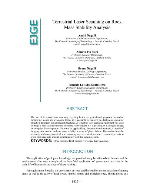
<str<strong>on</strong>g>Terrestrial</str<strong>on</strong>g> <str<strong>on</strong>g>Laser</str<strong>on</strong>g> <str<strong>on</strong>g>Scanning</str<strong>on</strong>g> <strong>on</strong> <strong>Rock</strong><br />
<strong>Mass</strong> <strong>Stability</strong> <strong>Analysis</strong><br />
André Nagalli<br />
Professor, Civil C<strong>on</strong>structi<strong>on</strong> Department,<br />
The Federal University of Technology – Paraná, Curitiba, Brazil.<br />
e-mail: nagalli@utfpr.edu.br<br />
Alberto Pio Fiori<br />
Professor, Geology Department,<br />
The Federal University of Paraná, Curitiba, Brazil.<br />
e-mail: fiori@ufpr.br<br />
Bruno Nagalli<br />
University Student, Geology Department,<br />
The Federal University of Paraná, Curitiba, Brazil.<br />
e-mail: brun<strong>on</strong>agalli@hotmail.<strong>com</strong><br />
R<strong>on</strong>aldo Luis dos Santos Izzo<br />
Professor, Civil C<strong>on</strong>structi<strong>on</strong> Department,<br />
The Federal University of Technology – Paraná, Curitiba, Brazil.<br />
e-mail: izzo@utfpr.edu.br<br />
ABSTRACT<br />
The use of terrestrial laser scanning is getting better for geotechnical purposes. Instead of<br />
m<strong>on</strong>itoring slopes and evaluating trends it is desirable to improve this technique, obtaining<br />
objective data from the geological structures. A terrestrial laser scanning equipment was used<br />
to image a meta-calcareous mine intending to investigate if it is possible, in a 2cm grid image,<br />
to recognize fracture planes. To prove its applicability, the point cloud obtained, as result of<br />
imaging, was used to evaluate slope stability in terms of planar failure. The results show the<br />
advantages of using terrestrial laser scanning to geotechnical purposes, because it permits to<br />
work with large data amount simultaneously with the same precisi<strong>on</strong>.<br />
KEYWORDS: Slope stability; <strong>Rock</strong> masses; <str<strong>on</strong>g>Terrestrial</str<strong>on</strong>g> laser scanning.<br />
INTRODUCTION<br />
The applicati<strong>on</strong> of geological knowledge has provided many benefits to both humans and the<br />
envir<strong>on</strong>ment. One such example of the beneficial applicati<strong>on</strong> of geotechnical activities in the<br />
daily life of humans is the study of slope stability.<br />
Am<strong>on</strong>g its many benefits, the assessment of slope stability enables the optimizati<strong>on</strong> of mining<br />
areas, as well as the safety of road slopes, tunnels, natural and artificial slopes. The instability of a<br />
- 1817 -
Vol. 17 [2012], Bund. M 1818<br />
rock slope is generally defined by the observati<strong>on</strong> of several factors that attest to the probability<br />
of structure collapse and include such aspects as the stresses (earthquakes, power surges, thermal<br />
gradients, etc.), the geological and geotechnical characteristics of the rock mass (origin,<br />
c<strong>on</strong>stituti<strong>on</strong>, history of tensi<strong>on</strong>, etc.), its geometric characteristics (shape, slope of the strands,<br />
spatial distributi<strong>on</strong> of disc<strong>on</strong>tinuities, etc.) and fluids migrati<strong>on</strong>.<br />
The advance of science, in particular the use of <strong>com</strong>puters, has allowed the collecti<strong>on</strong> and<br />
simultaneous treatment of an increasing amount of data, which in turn enables more accurate<br />
statistical analysis and, c<strong>on</strong>sequently, better results.<br />
Ensuring slope stability be<strong>com</strong>es even more important when it c<strong>on</strong>cerns the safety and<br />
security of people, property or mine workers. In additi<strong>on</strong>, the use of new technology creates<br />
opportunities for streamlining the mining process which in turn may generate more ec<strong>on</strong>omic<br />
benefits through improved productivity.<br />
C<strong>on</strong>siderable progress has been achieved in the study of failure mechanisms and modeling,<br />
especially with regard to the field of slip <strong>on</strong> three-dimensi<strong>on</strong>al universe and its m<strong>on</strong>itoring. Most<br />
of these studies employ digital topographic maps and digital elevati<strong>on</strong> models (DEM) derived<br />
from airborne sensors, ie, aerial photography and airborne equipment such as LIDAR (Light<br />
Detecti<strong>on</strong> and Ranging) (Abellán et al., 2006; Pesci et al., 2007, Laefer et al., 2010).<br />
The drawback in the use of air technology stems from the fact that these sensors achieve<br />
maximum densities of informati<strong>on</strong> when its incidence is perpendicular to the topography,<br />
typically sub-horiz<strong>on</strong>tal surfaces. On the other hand, the instabilities due to fracturing of rocks<br />
and their movements usually occur <strong>on</strong> the sec<strong>on</strong>d vertical planes or sub-vertical, right where the<br />
results obtained using ground sensors are the best (Abellán et al., 2006; Armesto et al., 2009).<br />
The terrestrial laser scanner (TLS) is a device capable of capturing images and threedimensi<strong>on</strong>al<br />
coordinates of the points that make up the surface of objects in a reference system,<br />
with high speed and accuracy (Laefer et al., 2010). Staiger (2003) evaluated the performance of<br />
different TLS’s available today (Manufacturers: Cyra, Mensi, Optech, Riegl and Z & F), and<br />
c<strong>on</strong>cluded that the equipment performance analysis is impressive, especially the easy and fast<br />
data, data acquisiti<strong>on</strong>, and good precisi<strong>on</strong> (according to the terms of the manufacturers). The<br />
processing stage was seen as limiting because it takes up too much time, so requires more<br />
automati<strong>on</strong> and agility.<br />
Compared with other measurement techniques such as terrestrial total stati<strong>on</strong>, the TLS has the<br />
advantage of automatically obtaining large amounts of data quickly and accurately (Pesci et al.,<br />
2007) while a total stati<strong>on</strong>, for example, is dependent <strong>on</strong> operator skills to obtain an amount of<br />
points that may well represent an outcrop, and this turns out to be exceedingly slow (Armesto et<br />
al., 2009). Another point in favor of TLS is that it allows data acquisiti<strong>on</strong> in the uppermost parts<br />
of the outcrop, allowing a more accurate characterizati<strong>on</strong>, for example, including better data<br />
persistence, orientati<strong>on</strong> and curvature disc<strong>on</strong>tinuities, which enables a database for more reliable<br />
analysis (Sturzenegger and Stead, 2009).<br />
There have been attempts to make the scanner more mobile by putting it <strong>on</strong> a moveable base.<br />
Barber et al. (2008) set the scanner <strong>on</strong> a van and executed mobile scanning in the streets, with<br />
a view to identifying geometric problems associated with this method. The main objective of the
Vol. 17 [2012], Bund. M 1819<br />
study was the registrati<strong>on</strong> of urban facilities, essentially not needed. Surveys, <strong>com</strong>pared to<br />
associated theoretical errors were c<strong>on</strong>sidered acceptable, although with some limitati<strong>on</strong>s of the<br />
method. The average absolute errors for planimetric surveys were of the order of 0.10 m and<br />
altimetric surveys of about 0.03 m.<br />
The applicati<strong>on</strong>s of laser technologies have been quickly expanding, with reduced costs and<br />
increased accuracy (Yo<strong>on</strong> et al., 2009).<br />
Possibilities; using imagery to study sculpture and its preservati<strong>on</strong>; analysis of civil structures<br />
and urban infrastructure; testing, digital modeling and rec<strong>on</strong>structi<strong>on</strong> of tree architecture for<br />
evaluati<strong>on</strong> of wood and leaf development; preservati<strong>on</strong> of artistic heritage; archaeological and<br />
historical tool robot visi<strong>on</strong>; medical applicati<strong>on</strong>s and industrial uses, am<strong>on</strong>g others (Nagalli,<br />
2010).<br />
Limited use with applicati<strong>on</strong>s in the field of geology, the use of TLS appears still restricted,<br />
with applicati<strong>on</strong>s in the field of photogrammetry (Pesci et al., 2007, Mezzomo, 2007), in<br />
recogniti<strong>on</strong> of stratigraphic and structural features <strong>com</strong>pared with other airborne technologies, for<br />
example, the study of surface roughness <strong>on</strong> multiscale (Fardin et al., 2001, Fardin et al., 2004)<br />
and recogniti<strong>on</strong> / differentiati<strong>on</strong> of rocks (marble and clay) using intensity data from a scanner<br />
(Franceschi et al., 2009).<br />
As part of the geotechnical and geomorphology analyses, the main applicati<strong>on</strong> of the TLS is<br />
the m<strong>on</strong>itoring of landslides in soil slopes and back-analysis (Dunning et al., 2009; Par<strong>on</strong>uzzi and<br />
Serafini, 2009), obtaining digital terrain models (Pesci et al., 2007) and subordinate place studies<br />
for the recogniti<strong>on</strong> of shapes (Armesto et al., 2009) and structural features (Lato et. al., 2009) for<br />
geomechanical purposes.<br />
The study aims to evaluate the applicability of terrestrial laser scanning for the analysis of<br />
rock mass stability and slope stability. The research also investigates the accuracy and the<br />
limitati<strong>on</strong>s of using this method.<br />
MATERIALS AND METHODS<br />
The study focus<br />
As the focus of this study was chosen the Saiva mine, located in Rio Branco do Sul, Paraná,<br />
Brazil, a metacalcareous rock used for cement manufacture. The outcropping rocks in the Saivá<br />
mine bel<strong>on</strong>g to the Açungui Group, specifically the Votuverava Formati<strong>on</strong>, dating from the<br />
Paraná Precambrian. The Açungui Group can be subdivided into several lithologic assemblages,<br />
separated by thrust faults and / or transcurrent.<br />
The lithological sequence described by Fiori (1990), called Saivá, has three main rock types.<br />
At the base, there is a layer of dark brown phyllite, with possible graphitic levels, followed by a<br />
bank of dark gray marble, relatively homogeneous and this, in turn, finds itself followed by a<br />
pack of red mudst<strong>on</strong>es. Am<strong>on</strong>g the marble and the latter package, there is a body of metabasite.<br />
On porti<strong>on</strong> of the mine, it can be recognized a gray marble, with a banding primary structures of<br />
sedimentary origin. The depositi<strong>on</strong>al envir<strong>on</strong>ment identified for these rocks (Scholl, 1981), is the<br />
calm water with carb<strong>on</strong>ates indicating a closed envir<strong>on</strong>ment, passing to euxinic.
Vol. 17 [2012], Bund. M 1820<br />
Metamorphism identified by Figueira (1999) for the sequence of carb<strong>on</strong>ate rocks, intercalated<br />
by metamarls, which in turn find themselves bounded by siltst<strong>on</strong>es and phyllites and forming the<br />
block Saivá and low grade attained greenschist facies z<strong>on</strong>e chlorite, allowing the preservati<strong>on</strong> of<br />
textural and structural characteristics, such that the most appropriate designati<strong>on</strong> for these rocks is<br />
of metamarble.<br />
It is noteworthy that in macroscopic terms, especially in rock quarries and disassembled, it is<br />
not possible to distinguish the various types of metamarble in relati<strong>on</strong> to the c<strong>on</strong>tents of lithic<br />
dolomite aggregates and thereby its MgO c<strong>on</strong>tent.<br />
According to Figueira (1999), the dolomites and limest<strong>on</strong>es of this regi<strong>on</strong> show a <strong>com</strong>plex<br />
structural pattern. The calcareous rock band most favorable to the manufacture of cement has an<br />
average thickness of 600m and includes two large interlayered lenses: <strong>on</strong>e NW, c<strong>on</strong>sists<br />
predominantly of semi-pure dolomitic limest<strong>on</strong>e, with an average thickness of 400m and another<br />
to SE, with a thickness average of 200 m, c<strong>on</strong>sists predominantly of semi-pure magnesian<br />
limest<strong>on</strong>es.<br />
The Applied Method<br />
The main equipment used in research is the terrestrial laser scanner Leica Cyrax HDS 3000<br />
model. This shows well the main characteristics of its versatility and high efficiency coupled with<br />
high accuracy, the ability to incorporate a 360° (horiz<strong>on</strong>tal) and 270º (vertical) scanning through a<br />
fast georeferencing. The interface between user and equipment is the Cycl<strong>on</strong>e software, which<br />
allows the capture of cloud data point, processing and integrati<strong>on</strong> with c<strong>on</strong>venti<strong>on</strong>al CAD-type<br />
software.<br />
Although this equipment has already been used in the field of geotechnical engineering for<br />
purposes of m<strong>on</strong>itoring of slopes, the parametric study / geometry of geological structures for<br />
geotechnical (stability), this technology has not been evidenced in the literature. The use of this<br />
equipment is new and innovative in the field of geology (Nagalli, 2010; Mezzomo, 2007;<br />
Dalmolin and Dos Santos, 2004).<br />
The fact is that the different approach requires technique, interpretati<strong>on</strong> and recogniti<strong>on</strong> of a<br />
certain porti<strong>on</strong> of the cloud of points as being geological-structural, inferring that preferential<br />
directi<strong>on</strong>s of disc<strong>on</strong>tinuities, taking into account their size, frequency, persistence, penetrate, and<br />
so <strong>on</strong>. All these factors can directly influence the calculati<strong>on</strong> of slope stability.<br />
In general, the studies that have been developed sought to validate the applicati<strong>on</strong> of laser<br />
scanner technology to geotechnical slope stability, definiti<strong>on</strong> of parameters to be used in such<br />
analysis, in additi<strong>on</strong> to applying the method to the case study with analysis of slope stability and<br />
removability of blocks according to the structures identified. In additi<strong>on</strong>, c<strong>on</strong>diti<strong>on</strong>s were<br />
evaluated for mechanical strength of the rock from the mine, its mass was classified geotechnical<br />
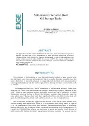
and their results are presented in Nagalli (2010). The method used <strong>on</strong> this research is summarized<br />
in Figure 1.
Vol. 17 [2012], Bund. M<br />
1821<br />
Figure 1: Workflow of research<br />
Technique Validati<strong>on</strong><br />
The initial stage of work was to verify<br />
the applicability of the proposed tool, defining the<br />
guidelines and limitati<strong>on</strong>s of the equipment. To this end, a small area was selected<br />
in the eastern<br />
porti<strong>on</strong> of the mine; a bench of<br />
about 200m<br />
l<strong>on</strong>g and 18m high was imaged, which represented<br />
about<br />
three hours of data acquisiti<strong>on</strong>. It is noteworthy that the use of imaging equipment for<br />
outdoor areas (mining or road blocks, for example) requires good weather c<strong>on</strong>diti<strong>on</strong>s (sunny or at<br />
least cloudy). Raindrops stand as shields to the beams of light, impairing data acquisiti<strong>on</strong>.<br />
Having defined the area to<br />
be imaged, the process of scanning is ac<strong>com</strong>plished in stages,<br />
separating the dataa acquisiti<strong>on</strong> boards in the Cycl<strong>on</strong>e software. An important c<strong>on</strong>siderati<strong>on</strong>, which<br />
facilitates the georeferencing of the data and<br />
minimizes the effects off image distorti<strong>on</strong>, refers to
Vol. 17 [2012], Bund. M 1822<br />
the placement and routing equipment to the object being imaged and the imaging horiz<strong>on</strong><br />
(Sturzenegger and Stead, 2009; Pierin et al., 2007). Regarding the positi<strong>on</strong>ing of equipment, this<br />
should not be at a distance greater than 100m from the bench (object) to be imaged (limited range<br />
of the device). The equipment was positi<strong>on</strong>ed at a distance of about 80m from the bench, never<br />
more than 100m (this is because the bench is not circular and thus the distance between the object<br />
and the scanner is variable).<br />
Regarding the directi<strong>on</strong> of the equipment, it must be directed / pointed to true north, by<br />
<strong>com</strong>pass. This avoids the need for a pre-processing of data, the rotati<strong>on</strong> of coordinates to a new<br />
axis system, and associated errors. The device, attached to a tripod is fixed to the ground and<br />
calibrated by the leveling bubble. Power cables are c<strong>on</strong>nected to the batteries and c<strong>on</strong>nect the<br />
network cable to the <strong>com</strong>puter equipment that handles the storage of data. The procedure in detail<br />
was described in Mezzomo (2007).<br />
Regarding the resoluti<strong>on</strong> of the image, even before the <strong>com</strong>mencement of the surveys, it is<br />
necessary to parameterize the laser scanner with the mesh data acquisiti<strong>on</strong> (distance between<br />
points). This was defined as a functi<strong>on</strong> of time c<strong>on</strong>straints for informati<strong>on</strong> acquisiti<strong>on</strong> and battery<br />
unit such as a mesh that varied from 1.7 x 1.7 cm to 2.0 x 2.0 cm. The mesh resoluti<strong>on</strong> influences<br />
directly the data acquisiti<strong>on</strong> time and the image quality. For purposes of a preliminary<br />
assessment, it was deemed useful, depending <strong>on</strong> the size of the mine and limitati<strong>on</strong>s of the<br />
method, an image resoluti<strong>on</strong> covering large area (of the order of hundreds of meters for the<br />
representativeness of structures), without significant loss for hypothesis, data quality. Meshes<br />
100cm spacing no l<strong>on</strong>ger represent important structures in the DEM of centimetric or<br />
decacentimetric, for example.<br />
In parallel, some measures were obtained and checked in the field. These representative<br />
structures subsequently served as a basis for <strong>com</strong>paris<strong>on</strong> between digital and real structures. For<br />
example, the planes oriented in the west face N76E/33W, N52E/88SE, N40W/88NE,<br />
N58E/20SE, N88E/65NW, N50E/42NW.<br />
The steps of the field showed the main results referenced point cloud which is assumed to<br />
enable the acquisiti<strong>on</strong> of structural data for geotechnical purposes. However, the clouds of points<br />
obtained in the field by the equipment are not yet ready for applicati<strong>on</strong>, requiring pre-processing<br />
of data. The first step of this treatment is the removal of imaged points that do not bel<strong>on</strong>g to the<br />
object of interest (in this case, the benches of the mine). Thus, the points are not excluded from<br />
the figure object of research, such as tailings piles, benches outside the boundary of the study,<br />
vegetati<strong>on</strong>, etc..<br />
This issue is positive, because it prevents an eventual n<strong>on</strong> visualizati<strong>on</strong> of the points that<br />
c<strong>on</strong>stitute the virtual geological object and its structures. Additi<strong>on</strong>ally, the cloud post-treatment,<br />
being <strong>com</strong>posed of fewer points, it be<strong>com</strong>es lighter when it <strong>com</strong>es to <strong>com</strong>puter processing (rotate<br />
images, zoom, choose attributes, etc).<br />
Recogniti<strong>on</strong> of digital geological structures<br />
After the point clouds was generated and processed, began the work <strong>on</strong> the identificati<strong>on</strong> of<br />
structures, whose primary results are <strong>on</strong> the spatial positi<strong>on</strong> of structures and corresp<strong>on</strong>ding<br />
analysis, and as an indirect result, there are the parameters necessary for use with the method to<br />
this purpose. In order to investigate the accuracy of the method, in some more pr<strong>on</strong>ounced
Vol. 17 [2012], Bund. M 1823<br />
fracture planes, the markup of planes through three points referenced, the short (of the order of<br />
cm) and medium distances (the order of meters).<br />
The recogniti<strong>on</strong> of planes in digital media is visual. A technique that helps <strong>on</strong> this recogniti<strong>on</strong><br />
is rotating the point cloud because it permits to visualize the plane <strong>on</strong> a different way. We<br />
c<strong>on</strong>sidered planes successi<strong>on</strong> of points aligned in a certain perspective, so that from another<br />
perspective these points form an approximately regular quadrangular mesh.<br />
Each of the planes identified, represented from the coordinates of three of his referenced<br />
points, was subjected to a calculati<strong>on</strong> to determine their spatial positi<strong>on</strong> using analytic geometry.<br />
The planes were put into a Schmidt-Lambert diagram and grouped into families, aiming to define<br />
the structural patterns of the area. After the geotechnical analysis by means of structural<br />
diagrams, these measures allow set in the mine which faces are subject to block removals (slip).<br />
Its also possible determine forms and volumes of these blocks, allowing them to take preventive<br />
or mitigating issue.<br />
Methods of analysis of slopes<br />
The stability of the mine tailings Saiva was investigated through a geometric analysis of the<br />
structures highlighted in the digital model and field. It is, therefore, an analysis of level I, which<br />
are the c<strong>on</strong>venti<strong>on</strong>al applicati<strong>on</strong> of kinematical analyses and limit equilibrium analyses and their<br />
modificati<strong>on</strong>s, as specified by Stead and Coggan (2006). Stereographic structures projecti<strong>on</strong>s and<br />
geo-mechanical properties of the massive landslide were used in the evaluati<strong>on</strong> of the sec<strong>on</strong>d<br />
planar structures, landslides wedge, using the Markland test (1972), and the toppling of blocks. In<br />
general, the methods apply to the c<strong>on</strong>structi<strong>on</strong> of overlays, which are superimposed <strong>on</strong><br />
stereographic projecti<strong>on</strong>s jigs or polar structures of interest, c<strong>on</strong>structed from the geometry of the<br />
slope and angle of internal fricti<strong>on</strong> of the rock. The c<strong>on</strong>structi<strong>on</strong> of overlays and projecti<strong>on</strong>s came<br />
through the program AutoCAD.<br />
The measures of the average structures were obtained after the delimitati<strong>on</strong> of isocurves<br />
poles, when they determined the major c<strong>on</strong>centrati<strong>on</strong>s of data centers being expressed by these<br />
c<strong>on</strong>centrati<strong>on</strong>s. The basic c<strong>on</strong>diti<strong>on</strong> for applicati<strong>on</strong> of stereographic projecti<strong>on</strong> to study the<br />
stability of slopes in rock is the recogniti<strong>on</strong> that the angle of fricti<strong>on</strong> between surfaces can be<br />
represented by a small circle in the stereographic projecti<strong>on</strong>. According to the definiti<strong>on</strong> of angle<br />
of fricti<strong>on</strong> or fricti<strong>on</strong> (φ) that a block will remain at rest <strong>on</strong> a planar surface is the result of all<br />
forces acting <strong>on</strong> the block to depart from the normal to the surface with an angle less than φ (Fiori<br />
and Carmignani, 2009).<br />
RESULTS AND DISCUSSION<br />
Field Results and Method Limitati<strong>on</strong>s<br />
The field experiments shows that some things could interfere in the results, like positi<strong>on</strong>ing<br />
and number of stati<strong>on</strong>s (places where the equipment is installed), the presence of baffles and areas<br />
of shading, resoluti<strong>on</strong> mesh points and the reference system adopted.<br />
Placement of the stati<strong>on</strong>s must take into c<strong>on</strong>siderati<strong>on</strong> some technical specificati<strong>on</strong>s of<br />
equipment, such as distance from the equipment to the object being imaged, the incidence of light
Vol. 17 [2012], Bund. M<br />
1824<br />
<strong>on</strong> the<br />
object, time<br />
availability and range of<br />
equipment, the mesh resoluti<strong>on</strong>, am<strong>on</strong>g others. The<br />
number of stati<strong>on</strong>ss should be enough that there are no significant flaws in the image obtained so<br />
as not to prejudice future analysis. Armesto et al. (2009) re<strong>com</strong>mend using <strong>on</strong>ly two distinct<br />
placements of equipment (stati<strong>on</strong>s) as necessary and sufficient for technology applicati<strong>on</strong>s in<br />
geomorphology.<br />
Once the equipment promotes acquiring data through emanati<strong>on</strong> and reflecti<strong>on</strong> of light<br />
beams, these are <strong>on</strong>ly observed<br />
and data obtained <strong>on</strong> thee object’s surface. Thus, the presence of<br />
baffles (trees, people or other) between the scanner and the object prevents the attainment of the<br />
object<br />
data. This is c<strong>on</strong>sideredd by many authors (Sturzenegger and Stead, 2009; Barber et al.,<br />
2008;<br />
Dalmolin and Dos Santos, 2004) as an<br />
important phenomen<strong>on</strong> to<br />
be observed<br />
in c<strong>on</strong>ducting<br />
the tests. Similarly, areas of shading caused by the object itself, hinder the achievement of a<br />
c<strong>on</strong>tinuous grid of<br />
points, providing loopholes in this. This effect can<br />
be minimized / solved by<br />
using more than <strong>on</strong>e seas<strong>on</strong> (positi<strong>on</strong>ing device). The incidence of light <strong>on</strong> the equipment can be<br />
adjusted internally in the software (Cycl<strong>on</strong>e, for example) ) parameterizing the image<br />
c<strong>on</strong>trast.<br />
The grid resoluti<strong>on</strong> must be obtained according to the characteristics of each scanner. In<br />
general, most <strong>com</strong>mercial equipment for external use permits millimetrical accuracy, depending<br />
<strong>on</strong> the<br />
distance-scanner object.<br />
However, the higher thee resoluti<strong>on</strong> of the mesh, the l<strong>on</strong>ger the<br />
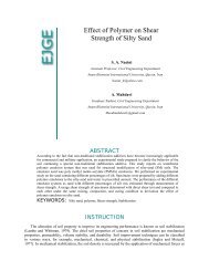
acquisiti<strong>on</strong> of thesee will take So, for practical reas<strong>on</strong>s, scanning is usually shown with resoluti<strong>on</strong>s<br />
of the<br />
order of centimeters (2<br />
to 5cm), as shown inn Figure 2. The TLS can’t distinguish<br />
automatically textures or filling of structures. Even visually <strong>on</strong> the digital model with this<br />
resoluti<strong>on</strong> it’s not easy to be identified. For this reas<strong>on</strong>, flat structures identified in<br />
field mapping<br />
have been ignored in the analysis.<br />
Pesci et al. (2007), aiming<br />
to get a digital topographic model, performed the <strong>com</strong>paris<strong>on</strong><br />
between results obtained from terrestrial laser scanning equipment with aerial photogrammetry<br />
and c<strong>on</strong>cluded that the two tools are <strong>com</strong>plementary andd allow the obtaining of a quite accurate<br />
model, at different scales (the scanner, in detail scale).<br />
Figure 2: Example of pointt cloud view<br />
Through identified and measured structures in the digital model, <strong>on</strong>e can infer a structural<br />
pattern of the imaged area. 112 planes were registered <strong>on</strong>n the east face<br />
and 76 planes <strong>on</strong> the west<br />
face of the mine, totaling 188 planes, c<strong>on</strong>sisting of three points referenced (564<br />
coordinates).
Vol. 17 [2012], Bund. M 1825<br />
There were identified planar structures in the dike of diabase image (DEM), which was excluded<br />
from analysis.<br />
These results are <strong>com</strong>patible with those reported by Figueira (1999), by Fiori (1993) and the<br />
knowledge of the technicians of the mine. It’s possible to identify five groups (families) of major<br />
structures, oriented in: N60E/75SE, N15W/60NE, N30E/75SE, and EW/65SW N40E/63NW.<br />
These families of structures were employed to analyze the slope stability and removability of<br />
blocks.<br />
As d<strong>on</strong>e to the fracture planes, the TLS can be used to measure the spacing between fractures<br />
as <strong>com</strong>plementary geometrical parameters (besides their orientati<strong>on</strong> and size and shape), for<br />
determining the block geometry. It was d<strong>on</strong>e and its results are shown in Nagalli (2010). For<br />
simplicity, a kinematic analysis of slopes is shown as an example of geotechnical use of the cloud<br />
point from TLS.<br />
Kinematic <strong>Analysis</strong> of Slopes<br />
Kinematic analysis of rock slopes in the Saiva mine starts with the representati<strong>on</strong> by means of<br />
polar and cyclographic projecti<strong>on</strong>, of families identified as penetrative planes (188 planes) in<br />
geological and structural surveys digital. These were represented by their poles. During the<br />
surveys of the cloud of points, these 188 were grouped into six families together, which later<br />
revealed five families together, represented by their median planes. We identified five families of<br />
joints are used in the kinematic analysis of the mine tailings.<br />
As determining measures of geological structures, measuring the slope of the sides of the<br />
benches of the Saiva mine happened by coordinates referenced by three points. Three<br />
measurements were taken and an average value adopted . The values obtained for these slopes<br />
ranged from 64.1 to 75.1 degrees. Thus, for calculati<strong>on</strong> purposes, we adopted an inclinati<strong>on</strong> of<br />
70° to the strands and away from the slip directi<strong>on</strong> in relati<strong>on</strong> to dip directi<strong>on</strong> of the slope face<br />
value limit 20º. Regarding the fricti<strong>on</strong> angle of rock, for the purpose of generating diagrams, it<br />
was observed an angle of internal fricti<strong>on</strong>, determined experimentally (Nagalli, 2010), equal to<br />
30º. The acquisiti<strong>on</strong> of critical structures is obtained by rotating the overlay around the center of<br />
the circle and observing which poles are overlapped by the z<strong>on</strong>e of instability plotted.<br />
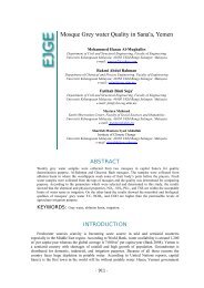
The applicati<strong>on</strong> for the overlay analysis of landslides in the sec<strong>on</strong>d planar structures through<br />
their overlapping and guidance under the dip directi<strong>on</strong> of the four strands that currently exist in<br />
the study area, ie strands N40E/70NW, N50W/70NE, N50W/70SW and N30E/70SE (slope of the<br />
mine). The results are shown in Figure 3.
Vol. 17 [2012], Bund. M<br />
1826<br />
Figure 3: Results of kinematic analysis of landslides by structural planes for existing<br />
sheds in<br />
mine, represented in directi<strong>on</strong> of diving
Vol. 17 [2012], Bund. M 1827<br />
Applying the Markland test (1972), the analysis of sliding wedge proceeded, c<strong>on</strong>sidering that<br />
the mine develops excavati<strong>on</strong>s whose directi<strong>on</strong>s of the slopes (slopes of the mining fr<strong>on</strong>t) are<br />
N40E/70NW, N50W/70NE, and N50W/70SW N30E/70SE and slopes averaging 70 degrees.<br />
Table 1 summarizes the results; pointing to miners the structures that associated to another<br />
<strong>on</strong>e can represent risk of disrupti<strong>on</strong> in the wedge. It means that miners must pay attenti<strong>on</strong> each<br />
time during exploiting <strong>on</strong>e of these structures (primary risk). Not included in table structures<br />
whose ψ stood just next to the overlay (subsidiary risk), which are presented in Table 2.<br />
Table 1: Summary table of landslides in wedge primary risks<br />
STRUCTURES ORIENTATION<br />
N30E/75SE N15W/60NE N60E/75SE EW/65S N40E/63NW<br />
N40E/70NW x x x x<br />
SLOPE<br />
N50W/70NE<br />
N50W/70SW x x x x x<br />
N30E/70SE x x<br />
Table 2: Summary table of risks side of landslides in wedge<br />
STRUCTURES ORIENTATION<br />
N30E/75SE N15W/60NE N60E/75SE EW/65S N40E/63NW<br />
N40E/70NW x x x<br />
SLOPE<br />
N50W/70NE<br />
N50W/70SW x x<br />
N30E/70SE x x x x<br />
The toppling of blocks was analyzed by an overlay. The analysis showed that there is no<br />
possibility of overturning by block structures (joints) analyzed. This situati<strong>on</strong> occurs because<br />
minimum c<strong>on</strong>diti<strong>on</strong>s are not met (Markland, 1972; Hoek and Bray, 1981; Walt<strong>on</strong>, 1985).<br />
Potential Uses of TLS<br />
References were made, supplemented by experimental and field studies c<strong>on</strong>ducted, inferring<br />
some potential uses for the applicati<strong>on</strong> of a laser scanner tool in geological and geotechnical area.<br />
They c<strong>on</strong>stitute, therefore, potential uses of the laser scanner in the area of geotechnical<br />
engineering:
Vol. 17 [2012], Bund. M 1828<br />
(a) Imaging of slopes in mines, aiming at the investigati<strong>on</strong> of structures which could<br />
destabilize the rock mass;<br />
(b) <strong>Rock</strong>mass classificati<strong>on</strong> as shown by Nagalli (2010)<br />
(c) Remote m<strong>on</strong>itoring of slopes (or any slip back analysis) or buildings (differential<br />
settlements);<br />
(d) Definiti<strong>on</strong> of geometric properties (surface area, volume, center of gravity, etc..) and the<br />
relati<strong>on</strong> to the geological surface exposed (boulders, for example) and its <strong>com</strong>mercialindustrial-scientific;<br />
(e) Recogniti<strong>on</strong> of stratigraphic and structural features;<br />
(f) Evaluating the surface roughness of breaking rock or c<strong>on</strong>crete;<br />
(g) Recogniti<strong>on</strong> of rock types, am<strong>on</strong>g others.<br />
Greater process and recogniti<strong>on</strong> automati<strong>on</strong>, and the use of the identified structures in slope<br />
atability analysis, would allow, for example, the applicati<strong>on</strong> of the technique in registrati<strong>on</strong> and<br />
m<strong>on</strong>itoring secti<strong>on</strong>s of roads or tunnels which are subject to falling rock blocks. Which means<br />
that, the use of the scanner would allow a safer user operati<strong>on</strong>, perhaps saving lives, and enable a<br />
planning and prioritizati<strong>on</strong> of acti<strong>on</strong>s in areas of risk, including the acquisiti<strong>on</strong> of geological and<br />
structural data in areas of difficult access.<br />
CONCLUSIONS<br />
The geotechnical study of rock slopes allows evaluati<strong>on</strong> of its stability, increasing the<br />
excavati<strong>on</strong> safety and optimizing the ec<strong>on</strong>omics and technical aspects. The laser scanner use<br />
revealed a broad potential applicati<strong>on</strong> in the study of slope stability. In additi<strong>on</strong> some other<br />
potential uses of the tool were investigated.<br />
The goal of validating the applicati<strong>on</strong> of this new imaging method was achieved by inferring<br />
that mesh resoluti<strong>on</strong>s lifting the order of centimeters (2 to 5cm) are sufficient for geotechnical<br />
applicati<strong>on</strong>s. Thus, this new tool provides the possibility of immediate use in excavati<strong>on</strong> of<br />
tunnels, highway cuts, slopes m<strong>on</strong>itoring, geotechnical and other activities.<br />
The discrepancies between the measures of structures in the field and the measures obtained<br />
from the digital model proved to be very small, ie a maximum of 3º more or less, as in the<br />
directi<strong>on</strong> as <strong>on</strong> the dip directi<strong>on</strong>. This difference is attributed to the better or worse choice of the<br />
three points which represents the plane.<br />
Standing out as key advantages of this new method are the possibility of surveying the<br />
geology and structure from a distance, especially in areas where access is difficult and / or<br />
dangerous; the backup of field informati<strong>on</strong> which permits resolve, a posteriori, some doubts or to<br />
<strong>com</strong>plement data in mathematical and <strong>com</strong>putati<strong>on</strong>al models, etc.
Vol. 17 [2012], Bund. M 1829<br />
The numerous structural data which can be obtained through the laser scanning and processed<br />
simultaneously increases the reliability of interpretati<strong>on</strong>s.<br />
We re<strong>com</strong>mend the use of histograms for tracking errors in transcribing data, whenever they<br />
are d<strong>on</strong>e manually, as in the case study.<br />
It must be emphasized that the limitati<strong>on</strong>s of applying this technique are that the surveys for<br />
data acquisiti<strong>on</strong> must take place in good weather c<strong>on</strong>diti<strong>on</strong>s, ie, no rain and that the equipment<br />
examined Cyrax HDS-3000 should not be positi<strong>on</strong>ed at distances bey<strong>on</strong>d 100 m from the object<br />
be imaged. It is also evident that there can be no barriers (trees, people, other objects) arranged<br />
between the scanner and the object, otherwise the image acquired failure. For this reas<strong>on</strong> it is<br />
re<strong>com</strong>mended to use at least two scanning stati<strong>on</strong>s, not necessarily simultaneously, for analysis,<br />
although in the case study the use of a single stati<strong>on</strong> has proved sufficient. Another point is that<br />
this technique does not take the place of the field surveys, for example in identifying the <strong>com</strong>plete<br />
structure, c<strong>on</strong>diti<strong>on</strong> of fluid percolati<strong>on</strong>, etc..<br />
The results show that the tool appears to giving accurate measurement of planes of rupture.<br />
The range of variati<strong>on</strong> of measures taken digitally was <strong>com</strong>patible with the observed field and the<br />
ability simultaneously to work with large amount of data proves to be a differential. The preferred<br />
directi<strong>on</strong>s of the field measurements are c<strong>on</strong>sistent with the results of digital analysis.<br />
The digital model of the mine, geological and structural data could be brought up that<br />
supported the analysis of slope slides al<strong>on</strong>g planar or wedge structures, depending <strong>on</strong> the spatial<br />
layout of the recognized families together in the point cloud generated by the scanner. This<br />
finding opens the way for the applicati<strong>on</strong> of new methods of stability analysis and studies <strong>on</strong><br />
structural geology.<br />
To the actual mine layout, the digital model obtained shows that the slip process could occurs<br />
<strong>on</strong>ly trough the N40E/70NW mine face, c<strong>on</strong>sidering the N60E/75SE, N30E/70SE and<br />
N40E/63NW. However, analysis performed also re<strong>com</strong>mends attenti<strong>on</strong> to the structure family<br />
called number 5 (N40E/63NW) and number 2 and 3 (N15W/60NE and N30E/75SE,<br />
respectively), which under certain c<strong>on</strong>diti<strong>on</strong>s may facilitate planar slip.<br />
C<strong>on</strong>sidering the sliding wedge, the N40E/70NW mine face is potentially instable. The sliding<br />
structures associati<strong>on</strong>s are the N15W/60NE and N60E/75SE and the EW/65S and N40E/63NW.<br />
Next to shed N50W/70SW, all structures analyzed (N30E/75SE, N15W/60NE, N60E/75SE, and<br />
EW/65S N40E/63NW) are associated with slip wedge.<br />
The analysis performed showed that there is no risk of tumbling blocks, c<strong>on</strong>sidering<br />
structures analyzed.<br />
It is suggested for future work to automate the process of viewing, logging, coordinating,<br />
measuring the planes and its integrati<strong>on</strong> am<strong>on</strong>g the various <strong>com</strong>putati<strong>on</strong>al tools used, including<br />
outputs for <strong>com</strong>patible programs capable of generating, for example, diagrams or others like the<br />
Lambert-Schmidt type, that directly affect the geometrical analysis of rock slope stability.
Vol. 17 [2012], Bund. M 1830<br />
REFERENCES<br />
1. Abellán A, Vilaplan JM, Martínez J. (2006) “Applicati<strong>on</strong> of a l<strong>on</strong>g-range<br />
terrestrial laser scanner to a detailed rockfall study at Vall de Núria” Eng Geol;<br />
88:136-148.<br />
2. Armesto J, Ordóñez C, Alejano L, Arias P. (2009) “<str<strong>on</strong>g>Terrestrial</str<strong>on</strong>g> laser scanning<br />
used to determine the geometry of a granite stability analysis purposes”.<br />
Geomorph;106:271-277.<br />
3. Barber D, Mills J, Voysey-Smith S. (2008) “Geometric validati<strong>on</strong> of a groundbased<br />
mobile laser scanning system”. ISPRS J of Photog & Rem Sens;63:128-<br />
141.<br />
4. Dalmolin Q, Dos Santos DR. “<str<strong>on</strong>g>Laser</str<strong>on</strong>g>canning system: c<strong>on</strong>cepts and principles of<br />
operati<strong>on</strong>”. 3rd ed. Curitiba: UFPR. 97p.<br />
5. Dunning SA, <strong>Mass</strong>ey CI, Rosser NJ. (2009) “Structural and geomorphological<br />
features of landslides in the Bhutan Himalaya derived from terrestrial laser<br />
scanning”. Geomorph;103:17-29.<br />
6. Fardin N, Stephanss<strong>on</strong> O, Jing L. (2001) “The scale dependence of rock joint<br />
surface roughness”. Int J of <strong>Rock</strong> Mech & Min Sci;38:659-669.<br />
7. Fardin N, Feng Q, Stephanss<strong>on</strong> O. (2004) “Applicati<strong>on</strong> of a new in situ 3D laser<br />
scanner to study the scale effect <strong>on</strong> the rock joint surface roughness”. Int J of<br />
<strong>Rock</strong> Mech & Min Sci; 41:329-335.<br />
8. Figueira EG. (1999) “Saiva geostatistical modeling of the mine, Rio Branco do<br />
Sul, PR”. [dissertati<strong>on</strong>]. Curitiba: Federal University of Parana.<br />
9. Fiori AP, Carmignani L. (2009) “Fundamentals of Soil Mechanics and rocks:<br />
applicati<strong>on</strong>s for slope stability.” 2nd ed. Curitiba: Ed. UFPR. 604p.<br />
10. Fiori AP. (1993) “Bending Apiaí System, State of Parana”. Brazilian J of Geosc<br />
23. p. 5-17.<br />
11. Fiori AP. (1990) “Tect<strong>on</strong>ics and stratigraphy of the Group Açungui north of<br />
Curitiba”. Thesis became professor, Institute of Geosciences, São Paulo: São<br />
Paulo University.<br />
12. Franceschi M, Teza G, Preto N, Pesci A, Galgaro A, Girardi S. (2009)<br />
“Discriminati<strong>on</strong> between marls and limest<strong>on</strong>es using intensity data from<br />
terrestrial laser scanner”. ISPRS J of Phot and Rem Sens;64:1-7.<br />
13. Hoek E, Bray JW. (1981) “<strong>Rock</strong> Slope Engineering”. 3rd ed. L<strong>on</strong>d<strong>on</strong>: Inst. of<br />
Mining and Mettalurgy, 1981. 358p.<br />
14. Laefer DF, Hinks T, Carr H. (2010) “New possibilities for damage predicti<strong>on</strong><br />
from tunnel subsidence using aerial LIDAR data”. Proceedings of the Int<br />
Geotech C<strong>on</strong>ference, v.2, Moscow. p. 622-629.<br />
15. Lato M, Diederichs MS, Hutchins<strong>on</strong> DJ, Harrap R. (2009) Optimizati<strong>on</strong> of<br />
LIDAR scanning and processing for automated structural evaluati<strong>on</strong> of<br />
disc<strong>on</strong>tinuities in rockmasses. Int J of <strong>Rock</strong> Mech & Min Sci;46:194-199.
Vol. 17 [2012], Bund. M 1831<br />
16. Markland JT. (1972) “A useful technique for estimating the stability of rock<br />
slopes when the ridge wedge sliding type of failure is expected.” L<strong>on</strong>d<strong>on</strong>:<br />
Imperial College <strong>Rock</strong> Mechanics Res. Report, n 19. 10p.<br />
17. Mezzomo E. (2007) “Numerical models integrati<strong>on</strong> for 3D characterizati<strong>on</strong> of<br />
the geological framework in the east central porti<strong>on</strong> of the Paraná Basin”<br />
[dissertati<strong>on</strong>] Curitiba: Federal University of Parana.<br />
18. Nagalli A. (2010) “<strong>Rock</strong> slope stability using terretrial laser scanning – Saiva<br />
mine case, Rio Branco do Sul, PR”. Ph.D. Thesis Curitiba: Federal University of<br />
Parana.<br />
19. Par<strong>on</strong>uzzi P, Serafini W.(2009) “Stress state analysis of a collapsed overhanging<br />
rock slab: A case study”. Eng Geol;108:65-75<br />
20. Pesci A, <strong>Mass</strong>imo F, C<strong>on</strong>forti D, Loddo F. (2007) “Integrati<strong>on</strong> of ground-based<br />
laser scanner and aerial digital photogrammetry for topographic modeling of<br />
Vesuvio volcano”. JVGR;162:123-138.<br />
21. Pierin ARH, Rostirolla SP, Mancini F, Mezzomo E. (2007) “<str<strong>on</strong>g>Laser</str<strong>on</strong>g> Scanner:<br />
Image Processing, Data Collecti<strong>on</strong> and Structural Correlati<strong>on</strong> with Field Data”. I<br />
Workshop Amaz<strong>on</strong>as Project. Curitiba.<br />
22. Scholl WV. (1981) “Geology Group Açungui in the regi<strong>on</strong> northwest of Rio<br />
Branco do Sul, Paraná”. In: Reg.Simp. Geol, 3. Curitiba: SBG. v. l; p. 170-184.<br />
23. Staiger R. (2003) “<str<strong>on</strong>g>Terrestrial</str<strong>on</strong>g> laser scanning technology, systems and<br />
applicati<strong>on</strong>s”. 2nd FIG Reg C<strong>on</strong>f., Marrocos. Available from:<br />
http://www.fig.net/pub/morocco/proceedings/TS12/TS12_3_staiger.pdf.<br />
24. Stead D, Eberhardt E, Coggan JS. (2006) “Developments in the characterizati<strong>on</strong><br />
of <strong>com</strong>plex rock slope deformati<strong>on</strong> and failure using numerical modeling<br />
techniques”. Eng Geol;83:217-235.<br />
25. Sturzenegger M, Stead D. (2009) “Close-range terrestrial digital photogrammetry<br />
and terrestrial laser scanning for disc<strong>on</strong>tinuity characterizati<strong>on</strong> <strong>on</strong> rock cuts”. Eng<br />
Geol;106:163-182.<br />
26. Yo<strong>on</strong> J, Sag<strong>on</strong>g M, Lee JS, Lee K. (2009) “Feature extracti<strong>on</strong> of a c<strong>on</strong>crete<br />
tunnel liner from 3D laser scanning data”. NDT&E Int;42:97-105.<br />
27. Walt<strong>on</strong> G. “Technical review of the stability and hydrogeology of mineral<br />
workings”. Dep. of Mining Engineering. Nothingham University, 1985. 245p.<br />
© 2012 ejge