SYPM 8R Instruction Sheet - Synergy Lighting Controls
SYPM 8R Instruction Sheet - Synergy Lighting Controls
SYPM 8R Instruction Sheet - Synergy Lighting Controls

You also want an ePaper? Increase the reach of your titles
YUMPU automatically turns print PDFs into web optimized ePapers that Google loves.
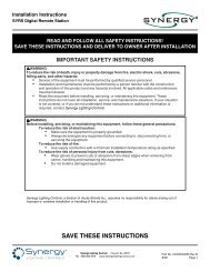
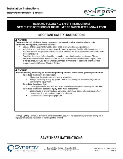
Installation <strong>Instruction</strong>s<br />
Relay Power Module - <strong>SYPM</strong> <strong>8R</strong><br />
R<br />
READ AND FOLLOW ALL SAFETY INSTRUCTIONS!<br />
SAVE THESE INSTRUCTIONS AND DELIVER TO OWNER AFTER INSTALLATION<br />
IMPORTANT SAFETY INSTRUCTIONS<br />
WARNING<br />
To reduce the risk of death, injury or property damage from fire, electric shock, cuts,<br />
abrasions, falling parts, and other hazards:<br />
• Service of the equipment must be performed by qualified service personnel.<br />
• Installation and maintenance must be performed by a person familiar with the construction<br />
and operation of this product and any hazards involved. All applicable codes and ordinances<br />
must be followed.<br />
• Read this document before installing, servicing, or maintaining this equipment. These<br />
instructions do not cover all installation, service, and maintenance situations. If your situation<br />
is not covered, or if you do not understand these instructions or additional information is<br />
required, contact <strong>Synergy</strong> <strong>Lighting</strong> <strong>Controls</strong>.<br />
WARNING<br />
Before installing, servicing, or maintaining this equipment, follow these general precautions.<br />
To reduce the risk of electrocution:<br />
• Make sure the equipment is properly grounded.<br />
• Always de-energize any equipment before connecting to, disconnecting from, or<br />
servicing the equipment.<br />
To reduce the risk of fire:<br />
• Use supply conductors with a minimum installation temperature rating as specified.<br />
To reduce the risk of personal injury from cuts, abrasions:<br />
• Wear gloves to prevent cuts or abrasions from sharp edges when removing from<br />
carton, handling and maintaining this equipment.<br />
• Do not install a damaged equipment.<br />
<strong>Synergy</strong> <strong>Lighting</strong> <strong>Controls</strong>, a division of Acuity Brands Inc., assumes no responsibility for claims arising out of<br />
improper or careless installation or handling of this product.<br />
SAVE THESE INSTRUCTIONS<br />
<strong>Synergy</strong> <strong>Lighting</strong> <strong>Controls</strong> Conyers Ga, 30012<br />
TEL : (800)-533-2719 www.<strong>Synergy</strong>lightingcontrols.com<br />
Part No. CDCS000226 REV N<br />
8/08<br />
Page 1
24V<br />
OFF<br />
4<br />
5<br />
6<br />
3<br />
7<br />
8<br />
2<br />
1<br />
9<br />
0<br />
A<br />
F<br />
B<br />
E<br />
D<br />
C<br />
C13<br />
J3 A B<br />
J4<br />
TB2<br />
TB4<br />
TB6<br />
TB8<br />
TB1<br />
TB3<br />
TB5<br />
TB7<br />
TB2<br />
TB4<br />
TB6<br />
TB8<br />
TB1<br />
TB3<br />
TB5<br />
TB7<br />
Installation <strong>Instruction</strong>s<br />
Relay Power Module - <strong>SYPM</strong> <strong>8R</strong><br />
R<br />
Quick Setup Guide<br />
Relay Module WITHOUT BREAKERS<br />
1<br />
SEE THE FOLLOWING PAGE FOR MODULES WITH BREAKERS<br />
Refer to the instructions on the following pages for complete details on the steps outlined below.<br />
Install the Relay Modules in the Enclosure.<br />
Install the first module in the top position as shown, then install additional<br />
modules in the positions below. Make sure the ribbon cable stays at the<br />
back of the enclosure behind the installed modules.<br />
2<br />
24V OFF COMMON<br />
24V OFF COMMON<br />
24V OFF COMMON<br />
24V OFF COMMON<br />
24V OFF COMMON<br />
24V OFF COMMON<br />
COMMON<br />
3<br />
4<br />
5<br />
6<br />
7<br />
2<br />
8<br />
1 0<br />
9<br />
A<br />
F<br />
E<br />
B<br />
D C<br />
Set Each Module Address to a Unique Address<br />
Rotate the address wheel to set the ID. Set the ID of the top module<br />
at "1" (as shown), the second at "2" and so on.<br />
24V<br />
OFF<br />
COMMON<br />
V+ IN1<br />
A<br />
V+<br />
IN2<br />
A<br />
ADDRESS<br />
3<br />
Connect the Ribbon Cable to Each Module<br />
4<br />
Test for Short Circuits in Load Wiring<br />
Test for short circuits in load wiring PRIOR to connecting<br />
load to relay output terminals.<br />
5<br />
6<br />
Connect Load Wiring as Shown in Figure 1<br />
Test Power Module Operation<br />
Turn on the cabinet power supply. Use the ON/AUTO/OFF switch to test the module. All module outputs should<br />
turn ON when the switch is in the right-most (ON) position and turn OFF when the switch is in the left-most (OFF)<br />
position. When testing is complete, return the switch to the AUTO (Center) postion. The ON/AUTO/OFF switch<br />
MUST be in the AUTO position for normal system operation and control from the system controller and low<br />
voltage inputs.<br />
7<br />
Connect Any Low Voltage Wiring (If Required) as Shown in Figure 1<br />
Part No. CDCS000226 REV N<br />
Page 2 8/08<br />
<strong>Synergy</strong> <strong>Lighting</strong> <strong>Controls</strong> Conyers Ga, 30012<br />
TEL : (800)-533-2719 www.<strong>Synergy</strong>lightingcontrols.com
24V<br />
OFF<br />
OFF<br />
OFF OFF<br />
OFF<br />
OFF OFF<br />
4<br />
5<br />
6<br />
3<br />
7<br />
8<br />
2<br />
1<br />
9<br />
0<br />
A<br />
F<br />
B<br />
E<br />
D<br />
C<br />
ON<br />
ON ON<br />
ON<br />
ON ON<br />
C13<br />
J3 A B<br />
J4<br />
SIGNAL ON +24V OFF COMMON<br />
TB2 TB1<br />
1<br />
SIGNAL ON +24V OFF COMMON<br />
2<br />
SIGNAL ON +24V OFF COMMON<br />
3<br />
TB4<br />
TB3<br />
SIGNAL ON +24V OFF COMMON<br />
4<br />
SIGNAL ON +24V OFF COMMON<br />
5<br />
SIGNAL ON +24V OFF COMMON<br />
6<br />
TB6<br />
TB5<br />
SIGNAL ON +24V OFF COMMON<br />
7<br />
SIGNAL ON +24V 8<br />
ON<br />
COM<br />
OFF<br />
SW1<br />
OFF<br />
AUTO<br />
ON<br />
V+<br />
V+<br />
OFF<br />
COMMON<br />
IN1<br />
IN2<br />
A<br />
A<br />
TB8<br />
TB7<br />
OFF<br />
OFF<br />
OFF<br />
OFF<br />
ON<br />
ON<br />
ON<br />
ON<br />
ON<br />
ON<br />
OFF<br />
OFF<br />
OFF OFF OFF OFF<br />
ON ON ON ON<br />
ON<br />
ON<br />
Installation <strong>Instruction</strong>s<br />
Relay Power Module - <strong>SYPM</strong> <strong>8R</strong><br />
R<br />
Quick Setup Guide<br />
Relay Module WITH BREAKERS<br />
1<br />
SEE THE FOLLOWING PAGE FOR MODULES WITHOUT BREAKERS<br />
Refer to the instructions on the following pages for complete details on the steps outlined below.<br />
Install the Relay Modules in the Enclosure.<br />
Install a neutral bar module in the top position. Install the first module in the<br />
top position as shown, then install additional modules in the positions<br />
below. Make sure the ribbon cable stays at the back of the enclosure<br />
behind the installed modules.<br />
OFF OFF<br />
24V OFF COMMON<br />
2<br />
24V OFF COMMON<br />
24V OFF COMMON<br />
24V OFF COMMON<br />
24V OFF COMMON<br />
24V OFF COMMON<br />
COMMON<br />
3<br />
4<br />
5<br />
6<br />
7<br />
2<br />
8<br />
1 0<br />
9<br />
A<br />
F<br />
E<br />
B<br />
D C<br />
Set Each Module Address to a Unique Address<br />
Rotate the address wheel to set the ID. Set the ID of the top module<br />
at "1" (as shown), the second at "2" and so on.<br />
24V<br />
OFF COMMON<br />
V+ IN1<br />
A<br />
V+<br />
IN2<br />
A<br />
3<br />
ADDRESS<br />
Connect the Ribbon Cable to Each Module<br />
4<br />
Connect the Power Feed Wiring to the Input Lugs<br />
The lugs accept #14 - 2/0 AWG conductors. Use the second lug to tap feed<br />
additional modules. See Figures 2 and 3 for typical feed wiring details.<br />
5<br />
Test for Short Circuits in Load Wiring<br />
Test for short circuits in load wiring PRIOR to connecting load to relay output terminals.<br />
6<br />
Connect Load Wiring as Shown in Figure 1<br />
7<br />
8<br />
Test Power Module Operation<br />
Turn on the cabinet power supply. Turn on all module circuit breakers. Use the ON/AUTO/OFF switch to test the<br />
module. All module outputs should turn ON when the switch is in the right-most (ON) position and turn OFF when<br />
the switch is in the left-most (OFF) position. When testing is complete, return the switch to the AUTO (Center)<br />
postion. The ON/AUTO/OFF switch MUST be in the AUTO position for normal system operation and control from<br />
the system controller and low voltage inputs.<br />
Connect Any Low Voltage Wiring (If Required) as Shown in Figure 1<br />
<strong>Synergy</strong> <strong>Lighting</strong> <strong>Controls</strong> Conyers Ga, 30012<br />
TEL : (800)-533-2719 www.<strong>Synergy</strong>lightingcontrols.com<br />
Part No. CDCS000226 REV N<br />
8/08<br />
Page 3
Installation <strong>Instruction</strong>s<br />
Relay Power Module - <strong>SYPM</strong> <strong>8R</strong><br />
R<br />
Before You Start<br />
1. Always disconnect all power.<br />
2. Install in accordance with the National Electrical Code<br />
and any other codes which may apply.<br />
3. Use only as intended and at the listed voltage.<br />
Important Module Installation Notes<br />
1. Install relay modules in cabinet starting at the top.<br />
Plug ribbon cable into each module before<br />
installing the next module. Ribbon cable installs<br />
behind modules.<br />
2. Verify the load type is compatible with voltages, loads<br />
and capacity listed on module label.<br />
3. Test branch circuits for short circuits prior to<br />
energizing module.<br />
4. Module input and output terminal specification (1)<br />
#10, #12, #14 AWG or (2) #12, #14 AWG maximum.<br />
5. Circuits with a fault current greater than 22k AIC<br />
should be wired with ONLY a single phase on each<br />
of the upper (TB2, 4, 6 & 8) or lower (TB1, 3, 5 & 7)<br />
circuit boards.<br />
7. DO NOT connect 2 or 3 pole circuits or loads to these<br />
relays. Equipment warranty void if multi-pole loads<br />
are controlled directly. Use <strong>Synergy</strong> 2, 3 or 4 pole<br />
accessory relays (SYA 2POLE/3POLE/4POLE) or<br />
external contactors only.<br />
Module Installation and Wiring<br />
1. MOUNT TOP MODULE<br />
Starting at the TOP of the cabinet, mount the module<br />
by setting the bottom tabs in the slots at the back of<br />
the cabinet then securing the top with the screws<br />
provided.<br />
2. SET MODULE ID AND CONNECT RIBBON CABLE<br />
Rotate the relay card ID switch to the address 1<br />
position. (See Figure 1) Plug the male connector on<br />
the ribbon cable into the female socket on the relay<br />
module. Ribbon cable installs behind the<br />
modules.<br />
3. Repeat steps 1 & 2 for additional modules,<br />
incrementing the relay card ID switches by 1 from<br />
the top of the cabinet down.<br />
Module Installation and Wiring Cont.<br />
4. PROVIDE PRIMARY POWER WIRING & BRANCH<br />
CIRCUIT CONNECTION<br />
Modules without breakers:<br />
Connect input terminal blocks TB1-TB8 to a 15 or 20<br />
amp single pole branch breaker. A branch breaker<br />
can be connected to several module input terminals<br />
if required. Make load wiring connections per<br />
Figure 1.<br />
Modules with breakers:<br />
Connect each module input lug to an appropriately<br />
sized conductor. Use the module's feed through lug<br />
to connect additional modules to the same phase<br />
input circuit. See Figure 1 for load connections and<br />
Figures 2 and 3 for typical feed wiring details.<br />
Refer to <strong>Synergy</strong> supplied As-Built drawings for more<br />
details. Test for short circuits prior to energizing<br />
module. Torque connection to 7 inch-lbs.<br />
5. CONNECT LOW VOLTAGE INPUT WIRING<br />
Inputs from contact closures should be terminated<br />
to the male spade connectors on the relay module.<br />
(See Figure 1) Refer to <strong>Synergy</strong> supplied As Built<br />
drawings, accessory instructions or project<br />
specifications for details.<br />
6. START-UP POWER MODULES TO ALLOW<br />
MANUAL LIGHTING CONTROL<br />
Following this procedure step by step will reduce the<br />
chance of damage due to relay closing on a short<br />
circuit. Module warranty void if relay closes on a<br />
short circuit.<br />
1. Turn off all Branch Breakers<br />
2.Verify the "Manual Override Switch" is in the ON<br />
position. (See Figure 1)<br />
3.Turn on circuit breaker for the enclosure power<br />
supply.<br />
4. Turn on branch breakers. Use the manual override<br />
switch for convenient on/off override.<br />
7. RELAY MODULE CONFIGURATION<br />
The relay cards are fully programmable with the<br />
addition of the system controller. Refer to the system<br />
controller installation instructions and <strong>Synergy</strong><br />
Operation Manual for more information.<br />
Part No. CDCS000226 REV N<br />
Page 4 8/08<br />
<strong>Synergy</strong> <strong>Lighting</strong> <strong>Controls</strong> Conyers Ga, 30012<br />
TEL : (800)-533-2719 www.<strong>Synergy</strong>lightingcontrols.com
Installation <strong>Instruction</strong>s<br />
Relay Power Module - <strong>SYPM</strong> <strong>8R</strong><br />
R<br />
Troubleshooting Procedures<br />
If the relay outputs do not come on follow these steps:<br />
1. Verify the correct voltage is present between the<br />
INPUT LUG and the NEUTRAL BUSS.<br />
2. Verify the cabinet power supply LEDs are on and<br />
the RIBBON CABLE is properly connected to the<br />
power supply and the module.<br />
3. Verify the module CIRCUIT BREAKERS are in the<br />
ON position (if applicable).<br />
4. Verify voltage is present on the output terminal<br />
block(s) and/or the output of the CIRCUIT<br />
BREAKERS.<br />
5. Switch the MANUAL OVERRIDE SWITCH to the<br />
“ON” position. All loads and RELAY OUTPUT<br />
STATUS LEDs should turn on.<br />
6. If relays remain "ON" after being signaled "OFF"<br />
check the circuit for overloads. If no overload is<br />
present, program the "phase" of the output using the<br />
controller. If the loads switch on/off using the manual<br />
override switch but do not respond to the controller,<br />
check the system programming. See the <strong>Synergy</strong><br />
Operation Manual for programming instructions.<br />
7. After testing is complete, switch the MANUAL<br />
OVERRIDE SWITCH to the “AUTO” position.<br />
If after performing the above tests one or more<br />
circuits still do not turn on, contact <strong>Synergy</strong><br />
<strong>Lighting</strong> <strong>Controls</strong> Technical Service department<br />
between the hours of 8 AM and 5 PM EST, Monday<br />
- Friday, at 800-533-271<br />
Visit <strong>Synergy</strong> <strong>Lighting</strong> <strong>Controls</strong> on the internet at http://www.synergylightingcontrols.com for further information on products,<br />
technical data or installation instructions.<br />
Warranty<br />
<strong>Synergy</strong> <strong>Lighting</strong> <strong>Controls</strong> warrants all equipment to be free from defect in manufacturing under normal and proper storage,<br />
installation, and operation for a period of one (1) year. Our guarantee liability extends only to the repair or replacement of the<br />
defective part and no labor charges for correction of the defect by repair or replacement will be honored by <strong>Synergy</strong> <strong>Lighting</strong><br />
<strong>Controls</strong> unless prior written authorization has been granted by our Customer Service Department.<br />
<strong>Synergy</strong> <strong>Lighting</strong> <strong>Controls</strong> Conyers Ga, 30012<br />
TEL : (800)-533-2719 www.<strong>Synergy</strong>lightingcontrols.com<br />
Part No. CDCS000226 REV N<br />
8/08<br />
Page 5
LK1<br />
LK1<br />
LK1<br />
LK1<br />
LK2<br />
LK2<br />
LK2<br />
LK2<br />
ALL OFF<br />
AUTO<br />
LK3<br />
LK3<br />
LK3<br />
LK3<br />
ALL ON<br />
LK4<br />
LK4<br />
LK4<br />
LK4<br />
ALL OFF<br />
ALL ON<br />
AUTO<br />
ALL OFF<br />
ALL ON<br />
AUTO<br />
LK 4<br />
LK 3<br />
LK 2<br />
LK 1<br />
4<br />
5<br />
6<br />
3<br />
7<br />
8<br />
2<br />
1<br />
9<br />
0<br />
A<br />
F<br />
B<br />
E<br />
D<br />
C<br />
Installation <strong>Instruction</strong>s<br />
Relay Power Module - <strong>SYPM</strong> <strong>8R</strong><br />
R<br />
LOW VOLTAGE<br />
CLASS 2 INPUTS<br />
RELAY OUTPUT STATUS LED<br />
(TYPICAL OF 8)<br />
MULTIPHASE BRANCH CIRCUIT WIRING<br />
WITH COMMON NEUTRAL<br />
MAINTAINED INPUT<br />
1<br />
PILOT ON COMMON OFF<br />
TB2<br />
TB1<br />
NEUTRAL<br />
MOMENTARY ALTERNATE INPUT<br />
3<br />
PILOT ON COMMON OFF<br />
TB4<br />
TB3<br />
LATCHING MOMENTARY<br />
INPUT W/OPTIONAL PILOT<br />
5<br />
6<br />
7<br />
PILOT ON COMMON OFF<br />
PILOT ON COMMON OFF<br />
PILOT ON COMMON OFF<br />
TB6<br />
TB5<br />
24 VDC ACCESSORY<br />
POWER / ANALOG INPUTS<br />
MANUAL OVERRIDE<br />
SWITCH<br />
+24V<br />
A1<br />
+24V<br />
A2<br />
MANUAL<br />
OVERRIDE<br />
ANALOG-IN<br />
ANALOG-IN<br />
ANALOG-RET<br />
ANALOG-RET<br />
TB8<br />
TB7<br />
15 OR 20 AMP 1 POLE<br />
120 or 277 VAC<br />
BRANCH CIRCUIT BREAKER<br />
PILOT OUPUT<br />
VOLTAGE SELECT<br />
1<br />
RIBBON CABE CONNECTION<br />
USE LK1 ONLY WHEN 3<br />
INCANDESCENT PILOT<br />
LAMPS ARE USED<br />
LK3 - 20 VDC OUPUT<br />
VOLTAGE TO PILOT LAMPS<br />
LK4 - 6 VDC OUPUT<br />
VOLTAGE TO PILOT LAMPS<br />
CONTROLLER<br />
COMMUNICATION LED<br />
RELAY CARD ID SWITCH<br />
ALL MODULES IN EACH CABINET<br />
MUST BE AT A UNIQUE NUMBER.<br />
START AT THE TOP OF THE<br />
CABINET BEGINNING WITH "1"<br />
LK2<br />
ON - 1 SECOND WARN TIME FOR<br />
WATTSTOPPER INTELISWITCH<br />
OFF - 8 SECOND WARN TIME FOR<br />
SWEEPSWITCH<br />
TB2<br />
TB1<br />
SINGLE CIRCUIT WITH<br />
MULTIPLIE SWITCH LEGS<br />
N<br />
PILOT ON COMMON OFF<br />
TB4<br />
TB3<br />
15 OR 20 AMP 1 POLE<br />
120 or 277 VAC<br />
BRANCH CIRCUIT<br />
BREAKER (TYPICAL)<br />
"RO" OPTION<br />
REMOTE OVERRIDE<br />
MANUAL<br />
OVERRIDE<br />
TB6<br />
TB8<br />
TB5<br />
TB7<br />
N<br />
SINGLE CIRCUIT WITH<br />
SINGLE SWITCH LEG<br />
MANUAL<br />
OVERIDE<br />
TO ADDITIONAL MODULES<br />
IN THIS CABINET<br />
FORCE OFF<br />
FORCE ON<br />
CONTRACTOR SUPPLIED CONDUCTOR<br />
2 #12 MAX PER TERMINAL<br />
Figure 1 - <strong>SYPM</strong> <strong>8R</strong> Wiring Detail<br />
Part No. CDCS000226 REV N<br />
Page 6 8/08<br />
<strong>Synergy</strong> <strong>Lighting</strong> <strong>Controls</strong> Conyers Ga, 30012<br />
TEL : (800)-533-2719 www.<strong>Synergy</strong>lightingcontrols.com
ON<br />
OFF<br />
ON<br />
OFF<br />
ON<br />
ON<br />
ON<br />
ON<br />
ON ON<br />
OFF OFF OFF OFF OFF OFF<br />
ON ON<br />
OFF OFF OFF OFF OFF OFF<br />
ON ON ON ON ON<br />
ON ON<br />
OFF OFF OFF OFF OFF OFF OFF<br />
ON ON ON ON ON<br />
OFF OFF OFF OFF OFF<br />
ON<br />
OFF<br />
ON<br />
OFF<br />
ON<br />
OFF<br />
ON ON ON<br />
OFF OFF OFF<br />
ON<br />
OFF<br />
ON<br />
OFF<br />
ON<br />
OFF<br />
ON<br />
OFF<br />
ON<br />
OFF<br />
ON<br />
OFF<br />
ON<br />
OFF<br />
ON ON ON ON<br />
ON ON ON<br />
OFF OFF OFF OFF OFF OFF OFF<br />
ON ON ON<br />
OFF OFF OFF<br />
ON<br />
OFF<br />
ON<br />
OFF<br />
ON<br />
OFF<br />
ON<br />
OFF<br />
ON ON ON<br />
OFF OFF OFF<br />
ON<br />
OFF<br />
ON<br />
OFF<br />
ON<br />
OFF<br />
ON<br />
OFF<br />
Installation <strong>Instruction</strong>s<br />
Relay Power Module - <strong>SYPM</strong> <strong>8R</strong><br />
R<br />
Three Phase Four Wire Main Feed Details<br />
<strong>SYPM</strong>B<br />
NBAR<br />
<strong>SYPM</strong>B<br />
NBAR<br />
<strong>SYPM</strong><br />
<strong>8R</strong>B1<br />
ON ON<br />
<strong>SYPM</strong><br />
<strong>8R</strong>B1<br />
ON ON<br />
<strong>SYPM</strong><br />
<strong>8R</strong>B1<br />
<strong>SYPM</strong><br />
<strong>8R</strong>B1<br />
<strong>SYPM</strong><br />
<strong>8R</strong>B1<br />
<strong>SYPM</strong><br />
<strong>8R</strong>B1<br />
<strong>SYPM</strong><br />
<strong>8R</strong>B1<br />
<strong>SYPM</strong><br />
<strong>8R</strong>B1<br />
<strong>SYPM</strong><br />
<strong>8R</strong>B1<br />
<strong>SYPM</strong><br />
<strong>8R</strong>B1<br />
Figure 2 - Large Enclosure Module Population<br />
Modules w/Breakers and Neutral Bar<br />
Figure 3 - Large Enclosure Module Population<br />
Modules w/Breakers, Neutral Bar and Main Breaker<br />
<strong>Synergy</strong> <strong>Lighting</strong> <strong>Controls</strong> Conyers Ga, 30012<br />
TEL : (800)-533-2719 www.<strong>Synergy</strong>lightingcontrols.com<br />
Part No. CDCS000226 REV N<br />
8/08<br />
Page 7