Built-In Natural Gas Grill Installation Guide - Help - Weber
Built-In Natural Gas Grill Installation Guide - Help - Weber
Built-In Natural Gas Grill Installation Guide - Help - Weber

Create successful ePaper yourself
Turn your PDF publications into a flip-book with our unique Google optimized e-Paper software.
<strong>Built</strong>-<strong>In</strong> <strong>Natural</strong> <strong>Gas</strong> <strong>Grill</strong> <strong>In</strong>stallation <strong>Guide</strong><br />
Vieluxe ® 27" <strong>Built</strong>-<strong>In</strong> <strong>Grill</strong><br />
(Model #: 360152)<br />
Any Surface<br />
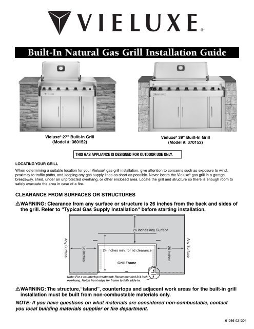
THIS GAS APPLIANCE IS DESIGNED FOR OUTDOOR USE ONLY.<br />
26 inches<br />
<strong>Grill</strong> Frame<br />
26 inches Any Surface<br />
24 inches min. for lid clearance<br />
Vieluxe ® 39" <strong>Built</strong>-<strong>In</strong> <strong>Grill</strong><br />
(Model #: 370152)<br />
LOCATING YOUR GRILL<br />
When determining a suitable location for your Vieluxe ® gas grill installation, give attention to concerns such as exposure to wind,<br />
proximity to traffic paths, and keeping any gas supply lines as short as possible. Never locate the Vieluxe ® gas grill in a garage,<br />
breezeway, shed, under an unprotected overhang, or other enclosed area. Locate the grill and structure so there is enough room to<br />
safely evacuate the area in case of a fire.<br />
CLEARANCE FROM SURFACES OR STRUCTURES<br />
�WARNING: Clearance from any surface or structure is 26 inches from the back and sides of<br />
the grill. Refer to "Typical <strong>Gas</strong> Supply <strong>In</strong>stallation" before starting installation.<br />
�WARNING: The structure,“island”, countertops and adjacent work areas for the built-in grill<br />
installation must be built from non-combustable materials only.<br />
NOTE: If you have questions on what materials are considered non-combustable, contact<br />
you local building materials supplier or fire department.<br />
26 inches<br />
Any Surface<br />
61266 021304
BUILT-IN STRUCTURE<br />
CUTOUT DIMENSIONS<br />
All dimensions are to finished surfaces.<br />
Figure 3<br />
BUILT-IN CUTOUT DIMENSIONS<br />
27" grill 39" grill Tolerances<br />
A 40 1 ⁄4" 52 1 ⁄4"<br />
B 36" 36"<br />
C 23" 23"<br />
+ 1 ⁄4<br />
- 1 ⁄4<br />
+ 1 ⁄4<br />
- 1 ⁄4<br />
+ 1 ⁄4<br />
- 1 ⁄4<br />
�WARNING: All countertop finished surfaces must<br />
be constructed of a noncombustible material.<br />
Note: If the supporting structure is going to have an<br />
electrical outlet for a rotisserie, it should be on the<br />
left side of the structure.<br />
2<br />
BUILT-IN GAS LINE<br />
LOCATIONS<br />
DIMENSIONS<br />
Figure 6<br />
Plan View<br />
Front of <strong>Grill</strong> Structure<br />
B<br />
C<br />
Front View<br />
VIELUXE ® BUILT-IN GAS LINE<br />
LOCATIONS<br />
27" grill 39" grill Tolerances<br />
A 4" 4"<br />
B 7" 7"<br />
C 2.5" 2.5"<br />
+ 1 ⁄8<br />
- 1 ⁄8<br />
+ 1 ⁄8<br />
- 1 ⁄8<br />
+ 1 ⁄8<br />
- 1 ⁄8<br />
Area should be kept clear of sharp, jagged, or extremely<br />
abrasive surfaces to avoid possible damage to gas supply<br />
lines. Exercise caution when pulling gas lines through<br />
built-in structure.<br />
Note: Leave an access in the “island” structure for<br />
gas supply and regulator service not inside the grill<br />
structure. Vieluxe ® has a gas line and regulator<br />
access door available from your dealer or call Vieluxe<br />
Customer Service at 1-866-VIELUXE. (Vieluxe ® part<br />
number 36311).<br />
A
TYPICAL GAS SUPPLY<br />
INSTALLATION<br />
WE RECOMMEND THAT THIS INSTALLATION BE<br />
DONE BY A LICENSED PROFESSIONAL.<br />
General Specifications for Piping<br />
Note - Contact your local municipality for building<br />
codes regulating outdoor gas grill installations. <strong>In</strong><br />
absence of Local Codes, you must conform to the<br />
latest edition of ANSI Z223.1./NFPA 54.<br />
■ This grill is designed to operate at 4.5 inches of water<br />
column pressure.<br />
■ A manual shut-off valve must be installed outdoors,<br />
and be accessible, not in the “built-in” structure. An<br />
additional manual shut-off valve indoors should be<br />
installed in the branch fuel line in an accessible<br />
location near the supply line.<br />
�CAUTION: If young children are in the area, a<br />
locking valve should be considered.<br />
■ Pipe compound should be used which is resistant to the<br />
action of natural gas when gas connections are made.<br />
■ The gas connections must be firmly attached to rigid,<br />
permanent construction.<br />
Note: The information provided in this manual is<br />
general for typical installations. We cannot cover all<br />
possible installation ideas. We recommend, prior to<br />
installation, that you contact your municipality for<br />
local building codes and your local fire department<br />
for installation requirements.<br />
3<br />
<strong>Gas</strong> line piping<br />
■ Refer to the piping chart at the bottom of the page.<br />
■ The corrugated gas line from the manifold is<br />
48 inches long. Do not extend the gas line.<br />
■ We have provided the means to make an SAE 45°<br />
flare connection. Do not use pipe sealant on<br />
this connection.<br />
■ If the length of line required does not exceed 50 feet,<br />
use a 5/8" O.D. tube. One size larger should be used<br />
for lengths greater than 50 feet.<br />
Refer to piping chart below.<br />
■ <strong>Gas</strong> piping may be copper tubing, type K or L;<br />
polyethylene plastic tube, with a minimum wall<br />
thickness of .062 inch; or standard weight (schedule<br />
40) steel or wrought iron pipe.<br />
If you have any questions, contact the Vieluxe ® Customer Service Center at 1-866-VIELUXE.<br />
Piping Chart<br />
Table 10-1 Maximum Capacity of Pipe in Cubic Feet of <strong>Gas</strong> per Hour for <strong>Gas</strong> Pressures of 0.5 psi or Less and<br />
a Pressure Drop of 0.3 <strong>In</strong>ch Water Column.<br />
(Based on a 0.60 Specific Gravity <strong>Gas</strong>)<br />
Nominal<br />
Iron Pipe <strong>In</strong>teral<br />
Size Diameter Length of Pipe (Feet)<br />
(inches) (inches) 10 20 30 40 50 60 70 80 90 100 125 150 175 200<br />
1/4 .364 32 22 18 15 14 12 11 11 10 9 8 8 7 6<br />
3/8 .493 72 49 40 34 30 27 25 23 22 21 18 17 15 14<br />
1/2 .622 132 92 73 63 56 50 46 43 40 38 34 31 28 26<br />
3/4 .824 278 190 152 130 115 105 96 90 84 79 72 64 59 55<br />
1 1.049 520 350 285 245 215 195 180 170 160 150 130 120 110 100<br />
1 1/4 1.380 1050 730 590 500 440 400 370 350 320 305 275 250 225 210<br />
1 1/2 1.160 1600 1100 890 760 670 610 560 530 490 460 410 380 350 320<br />
2 2.067 3050 2100 1650 1450 1270 1150 1050 990 930 870 780 710 650 610<br />
2 1/2 2.469 4800 3300 2700 2300 2000 1850 1700 1600 1500 1400 1250 1130 1050 980<br />
3 3.068 8500 5900 4700 4100 3600 3250 3000 2800 2600 2500 2200 2000 1850 1700<br />
4 4.026 17500 12000 9700 8300 7400 6800 6200 5800 5400 5100 4500 4100 3800 3500<br />
©1997 National Fire Protection Association, <strong>In</strong>c., and <strong>In</strong>ternational Approval Services - U.S., <strong>In</strong>c. All Rights Reserved.
TYPICAL GAS SUPPLY<br />
INSTALLATION (CONT.)<br />
■ Check your local building codes.<br />
<strong>Gas</strong> line piping (continued)<br />
■ Copper tubing must be tin-lined if the gas contains<br />
more than 0.3 grams of hydrogen sulfide per 100 cubic<br />
feet of gas.<br />
■ Plastic tubing is suitable only for outdoor,<br />
underground use.<br />
■ <strong>Gas</strong> piping in contact with earth, or any other material<br />
which may corrode the piping, must be protected<br />
against corrosion in an approved manner.<br />
■ Underground piping must have a minimum of 18" cover.<br />
Test connections<br />
All connections and joints must be thoroughly tested for<br />
leaks in accordance with local codes and all listed<br />
procedures in the latest edition of ANSI Z223.1/NFPA 54.<br />
�DANGER<br />
Do not use an open flame to check for gas<br />
leaks. Be sure there are no sparks or open<br />
flames in the area while you check for gas<br />
leaks. This will result in a fire or explosion<br />
which can cause serious bodily injury or death,<br />
and damage to property.<br />
Regulator<br />
■ The regulator should be adequately supported.<br />
■ The regulator must be installed close to<br />
the appliance.<br />
■ Each appliance must have a separate regulator.<br />
4<br />
CONNECT GAS SUPPLY<br />
TO REGULATOR<br />
Hard pipe the gas supply to the inlet of the regulator.<br />
Make a "T" fitting from your hard pipping if you plan on<br />
adding additional Vieluxe ® gas appliances.<br />
Refer to “Typical <strong>Gas</strong> Supply <strong>In</strong>stallation”.<br />
Connect the corrugated gas line to the regulator. Figure 1.<br />
Figure 2 shows the gas line and regulator assembled.<br />
Hard pipe the gas supply to the regulator. Figure 3.<br />
Figure 1<br />
<strong>Gas</strong> supply to manifold<br />
Figure 2<br />
<strong>Gas</strong> supply to manifold<br />
Figure 3<br />
Regulator<br />
Regulator<br />
Regulator<br />
Hard piped<br />
gas supply<br />
<strong>Gas</strong> supply to<br />
manifold<br />
Note: Leave an access in the “island” structure for<br />
gas supply and regulator service not inside the grill<br />
structure. Vieluxe ® has a gas line and regulator<br />
access door available from your dealer or call Vieluxe<br />
Customer Service at 1-866-VIELUXE.<br />
(Vieluxe ® part number 36311).
BUILT-IN GRILL<br />
INSTALLATION<br />
� CAUTION: Use two people to lift and install the<br />
Vieluxe ® grill.<br />
1) Lift the grill out of the packaging.<br />
2) Make sure that the Adjustable Feet are fully extended<br />
and secure before setting grill in place.<br />
3) Push the grill into the “island” structure making sure<br />
that the grill frame does not rest on the top of the<br />
“island” structure. Make sure the grill is resting on it’s<br />
Adjustable Feet only.<br />
4) <strong>Guide</strong> the gas line through the access hole in the<br />
grill frame while installing the grill.<br />
<strong>Grill</strong> Frame<br />
Adjustable Feet<br />
Foot fully extended<br />
and secured<br />
<strong>Gas</strong> Line<br />
Foot not fully extended<br />
5<br />
5) Lower the grill by adjusting the feet until the grill<br />
frame is resting firmly on the "island" countertop.<br />
Note: Make sure that the grill is level on the<br />
"island" countertop.<br />
<strong>Grill</strong> Frame<br />
"Island" Structure<br />
Countertop<br />
6) Once the grill is level with the top of the “island”<br />
structure, apply a bead of silcon sealant around the<br />
perimeter and front sides of the grill that is in contact<br />
with the “island” structure. This will prevent moisture<br />
seepage. The sealant you use must have a<br />
temperature rating above 120° F.<br />
Silicon<br />
Sealant
FLOOR PANEL<br />
INSTALLATION<br />
Once your grill has been set into place and the adjustable<br />
feet have be set to level your grill to the "island" structure<br />
countertop, install the floor panel.<br />
Vieluxe ® 27" <strong>Built</strong>-<strong>In</strong><br />
Vieluxe ® 39" <strong>Built</strong>-<strong>In</strong><br />
The floor panel will fit over the top of the adjustable feet.<br />
6<br />
VENTILATION<br />
�WARNING: Air holes must be provided in the<br />
structure at the top and bottom to provide<br />
ventilation in the event of a gas leak.<br />
Air holes can be located in a low visibility area and should<br />
be protected by screening material to prevent rodents and<br />
insects from entering the structure. Air holes will also help<br />
dry moisture.<br />
Vieluxe ® cabinet vents (#36312) are available from your<br />
dealer or call Vieluxe Customer Service at<br />
1-866-VIELUXE.<br />
Note: These drawings are only a reference.<br />
View of Left Side<br />
OR<br />
OR<br />
View of Right Side<br />
Front View Back View<br />
■ Cross ventilation must be incorporated in the<br />
supporting structure. We recommend a minimum of<br />
100 square inches of venting per side.<br />
■ Vents should be on two sides of the structure.<br />
The above drawings are for reference only.<br />
■ Location of the vents should be from the center,<br />
outward.<br />
■ Locate the vents at both the bottom of the structure<br />
and at the top of the structure.<br />
■ The bottom vents should be as close to ground level<br />
as possible. Make sure the vent area is not blocked<br />
by interior supports of the structure.<br />
■ We recommend vents with screens.<br />
■ Access doors to the structure are not considered vents.<br />
■ Clean the vents periodically.<br />
�DANGER: Failure to follow recommended minimum<br />
venting instructions can cause gas to collect in the<br />
structure in the event of a gas leak. This may result<br />
in a fire or an explosion which can cause serious<br />
bodily injury or death, and damage to property.
ASSEMBLY SUPPLIES NEEDED<br />
Note: Remove all packaging materials from the<br />
grill, the front, back, sides, inside the grill cart, and<br />
the bottom shipping platform. Once the packaging<br />
material is removed, carefully roll the grill off the<br />
shipping platform and lock the casters.<br />
REMOVE PACKAGED CONTENTS<br />
Flavorizer ® Bars<br />
Vieluxe ® 27" <strong>Built</strong>-<strong>In</strong><br />
Assemblies - (2)<br />
Single - (1)<br />
Vieluxe ® 39" <strong>Built</strong>-<strong>In</strong><br />
Assemblies - (3)<br />
Single - (2)<br />
Vieluxe ® Smoker (1)<br />
Cooking Grate<br />
Vieluxe ® 27" <strong>Built</strong>-<strong>In</strong> (2)<br />
Vieluxe ® 39" <strong>Built</strong>-<strong>In</strong> (3)<br />
Bottom Tray<br />
Catch Pan Holder<br />
Catch Pan<br />
Assembly<br />
Single<br />
7<br />
Warming Rack<br />
Rotisserie Motor Bracket<br />
Rotisserie Motor<br />
Rotisserie Split Fork<br />
Vieluxe ® 27" <strong>Built</strong>-<strong>In</strong> (2)<br />
Vieluxe ® 39" <strong>Built</strong>-<strong>In</strong> (4)<br />
Rotisserie Split Fork Screw<br />
Vieluxe ® 27" <strong>Built</strong>-<strong>In</strong> (2)<br />
Vieluxe ® 39" <strong>Built</strong>-<strong>In</strong> (4)<br />
Rotisserie Shaft Assembly
INSTALL FLAVORIZER ® BARS<br />
Vieluxe ® 27" <strong>Built</strong>-<strong>In</strong><br />
Parts required: (2) Flavorizer ® bar assemblies & (1) single Flavorizer ® bar.<br />
Set the Flavorizer ® bar assemblies and single Flavorizer ® bars front to back over the burners in the slots of the Flavorizer ®<br />
bar/cooking grill support.<br />
Note - Follow order of placement as shown in illustration. Starting from the Left, place a Flavorizer ® bar assembly, single<br />
Flavorizer ® bar then Flavorizer ® bar assembly.<br />
Flavorizer ® bar/Cooking grill support<br />
Flavorizer ® bar<br />
Slot<br />
Flavorizer ® bar/Cooking grill support<br />
Flavorizer ® bar<br />
Slot<br />
8<br />
Vieluxe ® 27" <strong>Built</strong>-<strong>In</strong><br />
Vieluxe ® 39" <strong>Built</strong>-<strong>In</strong><br />
Parts required: (3) Flavorizer ® bar assemblies & (2) single Flavorizer ® bars.<br />
Set the Flavorizer ® bar assemblies and single Flavorizer ® bars front to back over the burners in the slots of the Flavorizer ®<br />
bar/cooking grill support.<br />
Note - Follow order of placement as shown in illustration. Starting from the left, place a Flavorizer ® bar assembly, single<br />
Flavorizer ® bar, Flavorizer ® bar assembly, single Flavorizer ® bar, then Flavorizer ® bar assembly.<br />
Vieluxe ® 39" <strong>Built</strong>-<strong>In</strong>
INSTALL SMOKER<br />
Parts required: smoker box and smoker flues.<br />
Set the smoker box into the left side of the cooking box next to the Flavorizer ® bars. Then insert smoker flues with tabs<br />
into the cut-out of smoker box.<br />
The flues need to lay flat on top of the Flavorizer ® bars.<br />
Vieluxe ® 27" <strong>Built</strong>-<strong>In</strong> Vieluxe ® 39" <strong>Built</strong>-<strong>In</strong><br />
ADD COOKING GRATES<br />
Vieluxe ® 27" <strong>Built</strong>-<strong>In</strong><br />
Parts required: (2) cooking grates.<br />
The cross-rail of the cooking grate goes down. Set the<br />
cooking grates in place next to each other.<br />
Vieluxe ® 27" <strong>Built</strong>-<strong>In</strong><br />
9<br />
Vieluxe ® 39" <strong>Built</strong>-<strong>In</strong><br />
Parts required: (3) cooking grates.<br />
The cross-rail of the cooking grate goes down. Set the<br />
cooking grates in place next to each other.<br />
Vieluxe ® 39" <strong>Built</strong>-<strong>In</strong>
INSTALL WARMING RACK<br />
Part required: warming rack.<br />
<strong>In</strong>stall the warming rack into the slots at the right and left side of the cooking box.<br />
Vieluxe ® 27" <strong>Built</strong>-<strong>In</strong> Vieluxe ® 39" <strong>Built</strong>-<strong>In</strong><br />
INSTALL BOTTOM TRAY<br />
Parts required: bottom tray and catch pan holder.<br />
Note: It will be easier to install the catch pan holder by removing the catch pan from the holder.<br />
Hook the tabs of the catch pan holder into the slots of the bottom tray.<br />
10<br />
View from front of the Cooking Box<br />
Mounting<br />
Slots<br />
Tabs of<br />
bottom tray
Slide the bottom tray into the mounting slots under the bottom of the cooking box with the handle of the catch pan<br />
toward you.<br />
�CAUTION: Do not line the bottom tray with aluminum foil. It can cause grease fires by trapping the grease<br />
and not allowing grease to flow into the catch pan.<br />
Vieluxe ® 27" <strong>Built</strong>-<strong>In</strong><br />
INSTALL CATCH PAN<br />
Part required: catch pan.<br />
Take the catch pan by its handle and slide it into the catch pan holder under the bottom tray.<br />
Vieluxe ® 27" <strong>Built</strong>-<strong>In</strong> Vieluxe ® 39" <strong>Built</strong>-<strong>In</strong><br />
�WARNING: The storage space under the cooking module is intended for storage of<br />
nonflammable items only.<br />
11<br />
Vieluxe ® 39" <strong>Built</strong>-<strong>In</strong><br />
© 2004 <strong>Weber</strong>-Stephen Product Co.. Vieluxe ® is a registered U.S. trademark of <strong>Weber</strong>-Stephen Products Co.,<br />
200 East Daniels Road, Palatine, IL 60067-6266. U.S.A. 1-866-VIELUXE.