Centrala pentru automatizare porti Beninca HEAD - GTO Security ...
Centrala pentru automatizare porti Beninca HEAD - GTO Security ...
Centrala pentru automatizare porti Beninca HEAD - GTO Security ...

You also want an ePaper? Increase the reach of your titles
YUMPU automatically turns print PDFs into web optimized ePapers that Google loves.
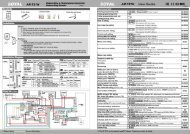
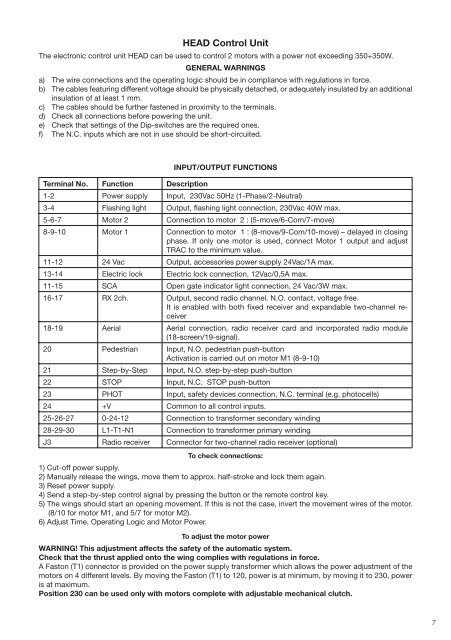
<strong>HEAD</strong> Control Unit<br />
The electronic control unit <strong>HEAD</strong> can be used to control 2 motors with a power not exceeding 350+350W.<br />
GENERAL WARNINGS<br />
a) The wire connections and the operating logic should be in compliance with regulations in force.<br />
b) The cables featuring different voltage should be physically detached, or adequately insulated by an additional<br />
insulation of at least 1 mm.<br />
c) The cables should be further fastened in proximity to the terminals.<br />
d) Check all connections before powering the unit.<br />
e) Check that settings of the Dip-switches are the required ones.<br />
f) The N.C. inputs which are not in use should be short-circuited.<br />
Terminal No. Function Description<br />
INPUT/OUTPUT FUNCTIONS<br />
1-2 Power supply Input, 230Vac 50Hz (1-Phase/2-Neutral)<br />
3-4 Flashing light Output, flashing light connection, 230Vac 40W max.<br />
5-6-7 Motor 2 Connection to motor 2 : (5-move/6-Com/7-move)<br />
8-9-10 Motor 1 Connection to motor 1 : (8-move/9-Com/10-move) – delayed in closing<br />
phase. If only one motor is used, connect Motor 1 output and adjust<br />
TRAC to the minimum value.<br />
11-12 24 Vac Output, accessories power supply 24Vac/1A max.<br />
13-14 Electric lock Electric lock connection, 12Vac/0,5A max.<br />
11-15 SCA Open gate indicator light connection, 24 Vac/3W max.<br />
16-17 RX 2ch. Output, second radio channel. N.O. contact, voltage free.<br />
It is enabled with both fixed receiver and expandable two-channel receiver<br />
18-19 Aerial Aerial connection, radio receiver card and incorporated radio module<br />
(18-screen/19-signal).<br />
20 Pedestrian Input, N.O. pedestrian push-button<br />
Activation is carried out on motor M1 (8-9-10)<br />
21 Step-by-Step Input, N.O. step-by-step push-button<br />
22 STOP Input, N.C. STOP push-button<br />
23 PHOT Input, safety devices connection, N.C. terminal (e.g. photocells)<br />
24 +V Common to all control inputs.<br />
25-26-27 0-24-12 Connection to transformer secondary winding<br />
28-29-30 L1-T1-N1 Connection to transformer primary winding<br />
J3 Radio receiver Connector for two-channel radio receiver (optional)<br />
To check connections:<br />
1) Cut-off power supply.<br />
2) Manually release the wings, move them to approx. half-stroke and lock them again.<br />
3) Reset power supply.<br />
4) Send a step-by-step control signal by pressing the button or the remote control key.<br />
5) The wings should start an opening movement. If this is not the case, invert the movement wires of the motor.<br />
(8/10 for motor M1, and 5/7 for motor M2).<br />
6) Adjust Time, Operating Logic and Motor Power.<br />
To adjust the motor power<br />
WARNING! This adjustment affects the safety of the automatic system.<br />
Check that the thrust applied onto the wing complies with regulations in force.<br />
A Faston (T1) connector is provided on the power supply transformer which allows the power adjustment of the<br />
motors on 4 different levels. By moving the Faston (T1) to 120, power is at minimum, by moving it to 230, power<br />
is at maximum.<br />
Position 230 can be used only with motors complete with adjustable mechanical clutch.<br />
7