Battery Management Systems - Battery Power Magazine
Battery Management Systems - Battery Power Magazine
Battery Management Systems - Battery Power Magazine

You also want an ePaper? Increase the reach of your titles
YUMPU automatically turns print PDFs into web optimized ePapers that Google loves.
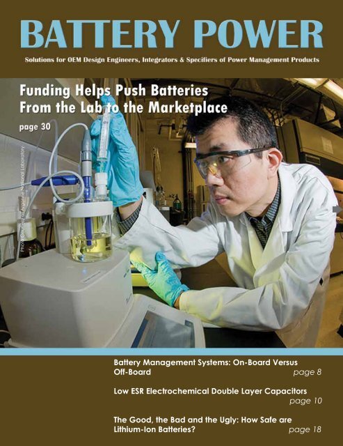
Photo Courtesy of Argonne National Laboratory<br />
<strong>Battery</strong> <strong>Management</strong> <strong>Systems</strong>: On-Board Versus<br />
Off-Board page 8<br />
Low ESR Electrochemical Double Layer Capacitors<br />
page 10<br />
The Good, the Bad and the Ugly: How Safe are<br />
Lithium-Ion Batteries page 18
Diagnose A Problem Before It Begins<br />
Inside this issue of<br />
March/April 2010<br />
Volume 14, Issue 2<br />
starting at<br />
$<br />
2,495<br />
Editor’s Choice<br />
GM Builds First Lithium-Ion <strong>Battery</strong> for<br />
Chevrolet Volt. . . . . . . . . . . . . . . . . . . . . . . . 4<br />
3554<br />
<strong>Battery</strong><br />
HiTester<br />
60VDC<br />
maximum<br />
between terminals<br />
• 60 Volt Range<br />
• Auto-hold &<br />
Auto-Data Storage<br />
• Enhanced resistance<br />
against UPS noise<br />
$<br />
2195 $<br />
439 95 $<br />
219 95 $<br />
2495<br />
• Store up to 4800 sets<br />
of data<br />
• USB PC Interface<br />
• Data management<br />
PC software<br />
...you need products you can depend on.<br />
Nextreme and Infinite <strong>Power</strong> Solutions<br />
Announce Thin-Film Thermal Charger<br />
Application. . . . . . . . . . . . . . . . . . . . . . . . . . .6<br />
Features<br />
<strong>Battery</strong> <strong>Management</strong> <strong>Systems</strong>: On-Board<br />
Versus Off-Board . . . . . . . . . . . . . . . . . . . . p 8<br />
Low ESR Electrochemical Double Layer<br />
Capacitors . . . . . . . . . . . . . . . . . . . . . . . .p 10<br />
Are You Charging Your Stationary<br />
Lead-Acid Batteries Properly . . . . . . . . p 14<br />
The Good, the Bad and the Ugly: How Safe<br />
Are Lithium-Ion Batteries. . . . . . . . . . . . .p 18<br />
New Products<br />
Batteries . . . . . . . . . . . . . . . . . . . . . . . . . . .p 20<br />
ICs and Semiconductors . . . . . . . . . . . . .p 21<br />
<strong>Power</strong> Supplies . . . . . . . . . . . . . . . . . . . . .p 23<br />
Charging & Testing. . . . . . . . . . . . . . . . . .p 24<br />
Eaton <strong>Power</strong> <strong>Systems</strong><br />
Aboard the World’s Largest<br />
Cruise Ship, page 6<br />
Toshiba’s New <strong>Battery</strong> Line,<br />
page 20<br />
Charge Up Without<br />
Plugging In, page 24<br />
3197<br />
<strong>Power</strong> Quality Analyzer<br />
3453<br />
Digital MΩ HiTester<br />
3454-11<br />
Digital MΩ HiTester<br />
3455-01<br />
High Voltage HiTester<br />
Measures:<br />
• <strong>Power</strong> & <strong>Power</strong> Factor<br />
• Active/Reactive Energy<br />
• Demand kWh<br />
• Load Changes (graph display)<br />
• Transient voltage/Inrush current<br />
Efficient Insulation Measurement<br />
• 125 V/40 M, 250 V/2000 M,<br />
500 V/2000 M, 1000 V/4000 M<br />
• Backlit Digital Display<br />
• Built-in memory<br />
• Auto discharge<br />
Insulation Resistance Tester<br />
• 250 V DC/500 V DC/1000 V DC<br />
• Comparator function<br />
• AC Voltage up to 750V<br />
• Built-in safety cover<br />
• Auto discharge<br />
5KV Compact Performance<br />
• Test Voltage 250V to 5kV<br />
• Measure insulation of high voltage<br />
equipment up to 5T Ω<br />
• Auto Calculate & Display PI and DAR<br />
• Data Storage & USB Interface<br />
Departments<br />
Industry News. . . . . . . . . . . . . . . . . . . . . . .p 26<br />
Calendar of Events. . . . . . . . . . . . . . . . . .p 29<br />
Marketplace. . . . . . . . . . . . . . . . . . . . . . . p 29<br />
Research & Development . . . . . . . . . . . p 30<br />
From Argonne National<br />
Lab to the Marketplace,<br />
page 30<br />
6 C O R P O R AT E D R I V E • C R A N B U R Y, N E W J E R S E Y<br />
P H O N E : 6 0 9 . 4 0 9 . 9 1 0 9 • FA X : 6 0 9 . 4 0 9 . 9 1 0 8<br />
w w w. h i o k i u s a . c o m<br />
Start or renew your subscription to <strong>Battery</strong> <strong>Power</strong> online at www.<strong>Battery</strong><strong>Power</strong>Online.com<br />
www.<strong>Battery</strong><strong>Power</strong>Online.com March/April • <strong>Battery</strong> <strong>Power</strong> 3
Editor’s Choice<br />
Editor’s Choice<br />
GM Builds First Lithium-Ion <strong>Battery</strong> for Chevrolet Volt<br />
Exactly three years since the<br />
day the Chevrolet Volt concept car<br />
debuted, GM has manufactured the<br />
first advanced lithium-ion battery for<br />
a mass-marketed electric vehicle at<br />
GM’s Brownstown <strong>Battery</strong> Pack Assembly<br />
Plant.<br />
GM announced last August a<br />
$43-million investment to prepare<br />
the 160,000 square-foot, landfill-free<br />
facility for production of lithium-ion<br />
battery packs for the Volt and other<br />
electric vehicles with extended-range capabilities. The plant is part of a whollyowned<br />
subsidiary of General Motors called GM Subsystems Manufacturing LLC.<br />
In five months, the Brownstown plant was converted from an empty facility to a<br />
production-ready battery manufacturing site. New machinery and specialized equipment<br />
have been installed and three primary assembly areas have been completed:<br />
battery module pre-assembly, final assembly and the battery pack main line.<br />
The Volt’s battery pack is made up of multiple linked battery modules and more<br />
than 200 battery cells. The initial assembly area is where the prismatic-shaped cells are<br />
processed and installed by state-of-the-art flexible automated equipment into modules,<br />
which are then delivered to the battery pack main line.<br />
The battery pack main line area features an Automated Guided Cart (ACG) system<br />
that includes operations for thermal and electrical assembly, along with quality and<br />
dimensional checks. The main line is also where battery pack final testing, verification<br />
and packaging for shipment take place.<br />
Initial battery production at Brownstown will be used to validate the plant’s equipment<br />
and processes, and batteries will be sent to GM’s Global <strong>Battery</strong> <strong>Systems</strong> lab in<br />
Warren, Mich., for testing. This spring, GM will begin shipping batteries to GM’s Detroit-Hamtramck<br />
plant, the assembly location<br />
for the Volt, for use in production validation<br />
vehicles. Regular production at Brownstown<br />
and Detroit-Hamtramck is set to begin in the<br />
fourth quarter.<br />
GM is investing $700 million in eight<br />
Michigan facilities for Volt-related production,<br />
including $336 million in the Detroit-Hamtramck<br />
plant, which will benefit from battery<br />
research conducted at the battery lab in Warren;<br />
receive batteries from Brownstown; use tooling<br />
from Grand Blanc; take delivery of camshafts<br />
and connecting rods from Bay City; and dies,<br />
stampings and the Volt’s 1.4L engine-generator from three plants in Flint.<br />
The Volt is an electric vehicle with extended-range capability. It is designed to drive<br />
up to 40 miles on electricity without using gasoline or producing tailpipe emissions.<br />
When the Volt’s lithium-ion battery is depleted of energy, a flex-fuel engine-generator<br />
seamlessly operates to extend the total driving range to about 300 miles before refueling<br />
or stopping to recharge the battery.<br />
NREL Evaluates UPS Hybrid-Electric Van Performance<br />
The US Department of Energy’s (DOE) National Renewable Energy Laboratory<br />
(NREL) has collected and analyzed fuel economy, maintenance and other vehicle performance<br />
data from UPS’s first generation hybrid diesel step delivery vans powered by<br />
an Eaton Corp. electric hybrid propulsion system.<br />
Photo Courtesy of GM Corp.<br />
Editor & Publisher • David Webster<br />
Director of Content • Shannon Given<br />
Associate Editors • Nick Depperschmidt,<br />
Heather Krier<br />
News Editors • Jeremy Fleming,<br />
Jessi Albers, Sue Hannebrink, Laura Mayo<br />
Manager of Administration<br />
Marsha Grillo<br />
Advertising, Sales and Marketing<br />
Jessi Albers, Director of Sales<br />
Jeremy Fleming, Account Executive<br />
Jennifer Graham, Marketing Assistant<br />
Julie Hammond, Production Manager<br />
Director of Support Services<br />
Marc Vang<br />
BATTERY POWER (ISSN #1092-3616)<br />
is published bi-monthly by Webcom Communications<br />
Corp., 7355 E. Orchard, #100<br />
Greenwood Village, CO 80111. Free for<br />
the qualified US $58.00 non-qualified US<br />
and $72.00 elsewhere.<br />
Periodicals Postage paid at Englewood, CO<br />
and additional mailing offices.<br />
POSTMASTER:<br />
Send address changes to:<br />
Webcom Communications<br />
7355 E. Orchard, #100<br />
Greenwood Village, CO 80111<br />
Reprints/Photocopies: For requests contact<br />
Webcom Communications at<br />
720-528-3770.<br />
© Copyright 2010 Webcom Communications<br />
Corp. Material in this publication<br />
may not be reproduced in any form without<br />
written permission. Requests for permission<br />
should be directed to the customer<br />
service manager.<br />
Webcom Communications Corp.<br />
7355 E. Orchard Rd., Suite 100<br />
Greenwood Village, CO 80111<br />
Phone 720-528-3770 • Fax 720-528-3771<br />
www.<strong>Battery</strong><strong>Power</strong>Online.com<br />
Office hours: 7 a.m. to 5 p.m. MST<br />
The diesel hybrid delivery vans improved the on-road fuel<br />
economy by 28.9 percent resulting in a 15 percent improvement<br />
in total cost per mile while maintaining similar reliability and<br />
operational performance as compared to conventional vehicles.<br />
Funded by the DOE’s Advanced Vehicle Testing Activity<br />
(AVTA), NREL’s Fleet Test & Evaluation (FT&E) team performed<br />
a 12 month evaluation of six of these hybrid vans at a<br />
UPS location in Phoenix.<br />
The report details the year-long demonstration project,<br />
including how the FT&E team collected and analyzed fuel<br />
economy, maintenance and other vehicle performance data on<br />
the vans, which are being used in delivery service. The project<br />
also tested a conventional and hybrid delivery van in NREL’s<br />
ReFUEL laboratory in Denver, Colo., and documented fuel<br />
economy and emissions performance on various test cycles.<br />
Eaton Corp. provided the hybrid propulsion systems for the<br />
vehicles, which were manufactured by Freightliner Corp. The<br />
hybrid system employs an Eaton automated transmission with<br />
an integrated motor/generator and advanced lithium ion batteries.<br />
Both the Freightliner hybrid model and the conventional<br />
model use a Mercedes-Benz MBE 904 four-cylinder diesel engine.<br />
UPS has recently ordered an additional 200 Eaton hybrid<br />
electric powered vans.<br />
The Eaton hybrid system was developed in part under a<br />
previous $7.5 million, 33 month contract from DOE’s Advanced<br />
Heavy Hybrid Propulsion System program.<br />
Limit Widespread Adoption of Electric Cars Over the<br />
Next Decade, Says The Boston Consulting Group<br />
Although electric-car battery costs are expected to fall sharply<br />
over the coming decade, they are unlikely to drop enough to<br />
spark widespread adoption of fully electric vehicles without a<br />
major breakthrough in battery technology, according to a new<br />
study by The Boston Consulting Group (BCG).<br />
The study concludes that the long-term cost target used<br />
by many carmakers in planning their future fleets of electric<br />
cars, $250 per kilowatt-hour (kWh), is unlikely to be achieved<br />
unless there is a major breakthrough in battery chemistry that<br />
substantially increases the energy a battery can store without<br />
significantly increasing the cost of either battery materials or the<br />
manufacturing process.<br />
“Given current technology options, we see substantial challenges<br />
to achieving this goal by 2020,” said Xavier Mosquet,<br />
Detroit-based leader of BCG’s global automotive practice and a<br />
coauthor of the study. “For years, people have been saying that<br />
one of the keys to reducing our dependency on fossil fuels is the<br />
electrification of the vehicle fleet. The reality is, electric-car batteries<br />
are both too expensive and too technologically limited for<br />
this to happen in the foreseeable future.”<br />
Most electric cars in the new decade will use lithium-ion<br />
batteries, which are lighter and more powerful than the nickelmetal<br />
hydride (NiMH) batteries used today in hybrids like the<br />
4 <strong>Battery</strong> <strong>Power</strong> • March/April<br />
www.<strong>Battery</strong><strong>Power</strong>Online.com<br />
www.<strong>Battery</strong><strong>Power</strong>Online.com March/April • <strong>Battery</strong> <strong>Power</strong> 5
Editor’s Choice<br />
Editor’s Choice<br />
Toyota Prius. Citing the current cost of similar lithium-ion<br />
batteries used in consumer electronics (about $250 to $400 per<br />
kWh), many original-equipment manufacturers (OEMs) hope<br />
that the cost of an automotive lithium-ion battery pack will fall<br />
from its current price of between $1,000 and $1,200 per kWh<br />
to between $250 and $500 per kWh at scaled production. BCG,<br />
however, points out that consumer batteries are simpler than car<br />
batteries and must meet significantly less demanding requirements,<br />
especially regarding safety and life span. So actual battery<br />
costs will likely be higher than what carmakers predict.<br />
Under the most likely scenario of the industry’s evolution,<br />
BCG estimates that 26 percent of the new cars sold in 2020 in<br />
the major developed markets (China, Japan, the US and Western<br />
Europe), or approximately 14 million cars, will have electric or<br />
hybrid power trains. That same year, the market for electric-car<br />
batteries in those regions will reach $25 billion.<br />
“This burgeoning market will be about triple the size of<br />
today’s entire lithium-ion-battery market for consumer applications<br />
such as laptop computers and cell phones,” said Mosquet,<br />
noting that the forecast applies to all the components sold to<br />
OEMs for battery packs.<br />
The report, titled Batteries for Electric Cars: Challenges,<br />
Opportunities and the Outlook to 2020, is a companion piece to<br />
a report BCG published in January 2009 on the future of alternative<br />
power-train technologies (The Comeback of the Electric<br />
Car How Real, How Soon, and What Must Happen Next). The<br />
new report’s findings are based on a detailed analysis of existing<br />
e-car battery research and interviews with more than 50 battery<br />
suppliers, auto OEMs, university researchers, start-up batterytechnology<br />
companies and government agencies across Asia, the<br />
US and Western Europe.<br />
Beyond costs, other key challenges facing the electric-car<br />
battery market are energy storage capacity, charging time and<br />
infrastructure needs. BCG believes that pending a major breakthrough,<br />
batteries will continue to limit the driving range of fully<br />
electric vehicles to some 250 to 300 kilometers (about 160 to<br />
190 miles) between charges. As a result, fully electric vehicles<br />
that are as convenient as ICE-based cars, meaning that they can<br />
travel 500 kilometers (312 miles) on a single charge and can<br />
recharge in a matter of minutes, are unlikely to be available for<br />
the mass market by 2020.<br />
Of the roughly 14 million electric cars forecast to be sold in<br />
2020 in China, Japan, the US and Western Europe, BCG projects<br />
that some 1.5 million will be fully electric, 1.5 million will<br />
be range extenders and 11 million will be a mix of hybrids.<br />
“In view of the need for a pervasive infrastructure for charging<br />
or swapping batteries, the adoption of fully electric vehicles<br />
in 2020 may be limited to specific applications, such as commercial<br />
fleets, commuter cars, and cars that are confined to a<br />
prescribed range of use,” the report concludes.<br />
World’s Largest Cruise Ship Sails with Safe, Reliable <strong>Power</strong> from Eaton<br />
When the world’s largest cruise ship, Oasis of the Seas,<br />
departed on its maiden voyage in December, a cadre of electrical<br />
power supply systems from Eaton Corp. helped to keep the<br />
ship’s 6,300 passengers comfortable, safe and entertained.<br />
Oasis of the Seas, the latest addition to the Royal Caribbean<br />
fleet, spans nearly 1,200 feet in length and has 16 passenger<br />
decks. The ship has more than 20 Eaton uninterruptible power<br />
system (UPS) units on board that provide a steady flow of<br />
power to its massive navigation, computer, emergency lighting<br />
and heating/cooling systems<br />
as well as its many restaurants,<br />
casinos and theaters.<br />
Built by STX Europe,<br />
Oasis of the Seas features<br />
a variety of Eaton’s largesystem<br />
marine UPS units to<br />
protect critical systems from<br />
disruptive power interruptions.<br />
Also included in the<br />
ship is Eaton’s power management<br />
software for electrical<br />
system performance<br />
monitoring<br />
and optimization.<br />
“We have been<br />
collaborating with<br />
Eaton in all of our<br />
most demanding<br />
cruise ship projects<br />
for more than 10<br />
years,” said Ville<br />
Talsi, system<br />
coordinator at STX<br />
Europe. “As these<br />
types of large-scale<br />
projects typically<br />
last more than<br />
Eaton electrical power systems aboard<br />
the world’s largest cruise ship, Oasis of the<br />
Seas, help keep the ship’s 6,300 passengers<br />
comfortable, safe and entertained. Photo<br />
courtesy of STX Europe.<br />
three years, it is crucial to have a reliable and trusted partner.<br />
Eaton’s high-quality products and field services around the<br />
world have guaranteed an enjoyable cruise experience for passengers<br />
and uninterrupted operation of the ships’ technology.”<br />
Nextreme and Infinite <strong>Power</strong> Solutions Announce<br />
Thin-Film Thermal Charger Application<br />
Nextreme Thermal Solutions, a provider in microscale<br />
thermal and power management products for the electronics<br />
industry, and Infinite <strong>Power</strong> Solutions, Inc. (IPS), a manufacturer<br />
of solid-state, rechargeable, thin-film micro-energy storage<br />
devices, have developed a thermal charger with the ability to<br />
continuously recharge the IPS Thinergy Micro-Energy Cell<br />
(MEC) using an eTEG thermoelectric power generator from<br />
Nextreme. Thin-film thermoelectric technology enables thermal<br />
charging where energy scavenging from thermal sources is combined<br />
with solid-state, rechargeable thin-film battery technology<br />
to provide an alternative energy source for a variety of autonomous,<br />
self-powered applications.<br />
The prototype thermal charger uses an array of 16 HV14<br />
modules in power generation mode to provide the 4.1 volts of<br />
electricity needed to charge the MEC to a fully charged state<br />
in approximately 20 minutes. At 0.5 millimeters high and each<br />
smaller than a sunflower seed, four of these HV14 power generators<br />
can replace a AA battery.<br />
Nextreme’s eTEG HV14 has demonstrated output power<br />
levels of >16 mW at ΔT of 70°C and >45 mW at ΔT of 120°C.<br />
With modules measuring 1.8 mm by 1.5 mm, the eTEG HV14<br />
has corresponding output power densities of ~ 0.6 and 1.6 W/<br />
cm². Nextreme’s eTEG devices generate electricity via the<br />
Seebeck Effect, where an electrical current is produced from a<br />
temperature gradient across the device.<br />
Unlike conventional batteries, these ultra-thin and rechargeable<br />
MECs can be solder attached directly to printed circuit<br />
boards (PCBs), or deeply embedded (buried) within the layers of<br />
a PCB. The MECs can also be embedded into integrated circuit<br />
packaging and multi-chip modules, as well as systems in package.<br />
The THINERGY MEC is provided to supply stored energy<br />
for use by the application during periods when the heat source is<br />
not available or is intermittent.<br />
Applications for thermal charging from waste heat include<br />
scavenging heat from a solar panel as a supplemental source of<br />
electricity, using heat produced by an engine during combustion<br />
to charge a battery, or providing power for a remote sensor.<br />
International <strong>Battery</strong> Chosen by S&C for First<br />
Community Energy Storage System<br />
International <strong>Battery</strong>, a US manufacturer and developer of<br />
large-format lithium-ion rechargeable batteries, has been chosen<br />
as the battery system provider for the first-of-its-kind Community<br />
Energy Storage (CES) systems, developed by S&C Electric<br />
Company for American Electric <strong>Power</strong>.<br />
Community Energy Storage is a concept for distributed energy<br />
storage initiated by AEP. The intent is to provide the utility<br />
and its customers benefits including load leveling, back-up power,<br />
support for plug-in electric car deployment as well as grid<br />
regulation and improved distribution line efficiencies. As more<br />
renewable energy sources such as wind and solar are integrated<br />
into the smart grid, managing and storing energy is essential due<br />
to the intermittent nature of these power sources.<br />
AEP Ohio’s gridSMARTSM Demonstration Project, funded<br />
in part by $75 million Department of Energy (DOE) stimulus<br />
funding, will be deployed to 110,000 AEP Ohio customers in<br />
northeast central Ohio. The project will integrate a broad range<br />
of advanced technologies in the distribution grid, utility back office<br />
and consumer premises with innovative consumer programs<br />
in order to demonstrate the many benefits of a smart grid for<br />
consumers and the utility. CES holds the promise of being an<br />
integral component of the smart grid.<br />
6 <strong>Battery</strong> <strong>Power</strong> • March/April<br />
www.<strong>Battery</strong><strong>Power</strong>Online.com<br />
www.<strong>Battery</strong><strong>Power</strong>Online.com March/April • <strong>Battery</strong> <strong>Power</strong> 7
Feature<br />
Sara Bradford, Principal Consultant<br />
Frost & Sullivan’s Energy & <strong>Power</strong> <strong>Systems</strong> Practice<br />
There are several schools of thought these days in regards<br />
to automotive battery management system (BMS) placement,<br />
whether the component should be mounted on- or off-board.<br />
The BMS is the brains behind plug-in hybrid (PHEV) and<br />
electric vehicles (EV), managing battery and other vital vehicle<br />
functions, so certainly this debate is essential in determining<br />
the proper technology and placement thereof to ensure years of<br />
increased PHEV and EV production without rapidly aging the<br />
charging infrastructure.<br />
<strong>Battery</strong> management systems work in real time to control<br />
many functions including battery monitoring, maintenance,<br />
regeneration, battery optimizing, failure prediction and/or<br />
prevention, battery data collection/analysis and planning. BMSs<br />
are an integral component of PHEVs and EVs to ensure proper<br />
battery operation and to protect the highly expensive automotive<br />
component.<br />
Apart from the battery module, the key components in the<br />
BMS include the following:<br />
• <strong>Battery</strong> Monitoring Unit (BMU): It uses a microprocessor<br />
based unit to monitor the various parameters such as state of<br />
charge, cell balancing and cell temperature and compares them<br />
with the specifications and communicate to the BCU. It also<br />
communicates with other devices through the CAN bus.<br />
• <strong>Battery</strong> Control Unit (BCU): It receives inputs from the<br />
BMU and incorporates any remedial measures needed to protect<br />
the battery or balance the cell or maintain the SOC. BCU is<br />
designed with power electronics components.<br />
BMS interfaces with a number of on-board vehicle systems<br />
as well as critical battery functions. For example, BMS<br />
determines what operating mode is currently underway such<br />
as braking, accelerating, stop/start and idling, and executes the<br />
correct electrical power management commands necessary for<br />
reliable operation.<br />
BMS is a key component in HEVs and EVs. BMS performs<br />
the role of interfacing with number of on-board automotive<br />
systems, when the battery undergoes rapid charge, discharge<br />
cycles as and when the vehicle accelerates and brakes. Some of<br />
the main functions of BMS in a HEV and EV are listed below:<br />
• Monitor parameters of individual cells that makes the<br />
battery module<br />
• Protect the cells from reaching the threshold condition<br />
• Provide ‘safe mode’ abort or the ‘fail safe’ mechanism for the<br />
components of BMS during uncontrolled extreme conditions<br />
• Isolate the battery systematically during emergency conditions<br />
• Provide parameters in the driver displays and<br />
alarm functions<br />
• Predict the range and distance possible with the remaining<br />
<strong>Battery</strong> <strong>Management</strong> <strong>Systems</strong><br />
On-Board Versus Off-Board<br />
charge in the battery<br />
• Provide mean of access for charging individual cells<br />
• Offer ‘emergency mode of operation’ in case of<br />
unexpected contingencies.<br />
On-Board BMS Mounting<br />
As the PHEV and EV market is rapidly evolving, vehicle<br />
OEMs are working quite independently when it comes to battery<br />
technology integration. In terms of battery chemistries, secondary<br />
lithium-ion has emerged over the last several years as<br />
a viable option for next-generation electric vehicles. However,<br />
lead acid still remains the technology of choice for low-range<br />
battery-powered EVs. Therefore, each vehicle developed is<br />
unique when it comes to battery management, each employing<br />
proprietary algorithm for the BMS. With a simple comparison<br />
of PHEV or EV passenger vehicles under development, each<br />
is unique in terms of battery charging algorithm, rate of charge<br />
acceptance, volt and amp communication to the charger and<br />
ultimately power delivery to the vehicle.<br />
For Level I and Level II chargers to accommodate the<br />
numerous proprietary charging algorithms, unique vehicles and<br />
battery configurations would be difficult and highly expensive.<br />
Additionally, with the rapidly changing EV industry, these configurations<br />
are likely to change each year or by model upgrade.<br />
The key issues revolving around on-board BMS include<br />
the following:<br />
• Additional weight added to battery pack<br />
• Charging components required in the pack, further adding to<br />
the overall pack weight<br />
• Communication protocol is not industry standard in terms of<br />
charger interaction<br />
• On-board BMS requires the supplied voltage, phase<br />
configuration and maximum current capacity of the<br />
charging station.<br />
Off-Board BMS<br />
For standard chargers, battery management algorithms have<br />
always been a key technology feature. Charger companies<br />
would essentially program each charger to manage specific<br />
battery types requiring various levels of voltage, rate of charge<br />
acceptance, volt and amp communication to the charger and<br />
ultimately power delivery to the equipment. However, it would<br />
be comparing apples to oranges if you compare conventional<br />
charger technology for a starting battery or consumer electric<br />
device to a highly sophisticated PHEV or EV charger.<br />
There are certain irregularities involved with the current<br />
charging station models that are reaching reality in the EV<br />
infrastructure development. Chargers must be able to deliver<br />
the correct voltage and amps to the vehicle, regardless of<br />
make or model. At this point in development, Level I or Level<br />
II chargers are most prominent with other chargers able to<br />
supply both Level I and Level II loads. Ultimately, Level III<br />
chargers will also enter the charging station equation. Therefore,<br />
there are minimal standards in terms of chargers and the<br />
power delivery. BMS are highly unique to vehicle and battery<br />
and therefore would be quite costly to integrated off-board by<br />
charging station.<br />
The key issues revolving around off-board BMS are as follows:<br />
• Highly complex and expensive to incorporate BMS into<br />
charging stations<br />
• Plug-in hybrid electric vehicles and standard<br />
HEVs incorporate regenerative to recharge<br />
battery, requiring a less complex BMS<br />
• Charging station would be responsible for<br />
incorrect charging algorithm, which could<br />
result in irreversible battery damage<br />
• Off-board BMS would not be able to identify<br />
malfunctioning cells in the pack, cycle<br />
individual cells at various rates, or<br />
assess cell SOC in the pack as each pack varies<br />
in specifications and overall circuitry.<br />
Conclusion<br />
At the end of the day, charger companies<br />
must partner closely with battery pack manufacturers<br />
to ensure proper battery handling. Communication<br />
between the battery cell and pack<br />
manufacturers and the charger companies is critical<br />
to minimize improper battery charging. Additionally,<br />
charger vendors should continue to test<br />
all cells to determine correct charging algorithm.<br />
Correct pack state-of-charge and state-of-health<br />
are essential for proper battery performance,<br />
including realistic cycle life specifications.<br />
<strong>Battery</strong> management systems are also frequently<br />
used in other battery applications such<br />
as standby power, marine, material handling,<br />
off-grid power systems and battery banks for alternative<br />
energy sources, among others. Similar<br />
requirements exist for these applications as exist<br />
for the automotive market. Overall, the demand<br />
for robust, reliable and optimal cell and pack<br />
control is common for any battery application.<br />
Sara Bradford is a<br />
principal consultant<br />
with the Frost & Sullivan<br />
North American<br />
Energy and <strong>Power</strong><br />
<strong>Systems</strong> Practice. She<br />
focuses on monitoring<br />
and analyzing<br />
emerging trends,<br />
technologies and<br />
market dynamics in<br />
<strong>Battery</strong> <strong>Management</strong> <strong>Systems</strong><br />
the battery, alternative energy, fuel cell, power supplies/power<br />
quality and energy industries worldwide.<br />
For more information regarding this article, please contact<br />
Johanna Haynes at johanna.haynes@frost.com.<br />
The Ideal Packaging<br />
Material for <strong>Battery</strong> Packs<br />
R10404: Thermally Conductive<br />
Silicone Sponge<br />
> Thermally Dissipative<br />
> Shock/Vibration Cushioning<br />
> Electrical Isolation<br />
> High Temperature Resistance and Operating<br />
> Long Service Life<br />
> No Cure Cycle Required<br />
> Stays Soft and Compliant<br />
> Adhesive Options<br />
> Durable and Tear-resistant<br />
R10404 is a member of the COHRlastic brand,<br />
the premium silicone sponge market solution.<br />
www.cohrlastic.saint-gobain.com<br />
Performance<br />
Taking Shape<br />
Every day, Saint-Gobain<br />
products provide customers<br />
with the highest levels<br />
of performance —<br />
performance which is the<br />
result of creative ideas and<br />
innovative technologies.<br />
A recognized leader<br />
in advanced polymer<br />
technology, Saint-Gobain<br />
Performance Plastics is part<br />
of an international family<br />
of companies comprising<br />
Compagnie de Saint-Gobain,<br />
a global force in engineered<br />
materials.With a worldwide<br />
network of manufacturing<br />
and sales facilities, Saint-<br />
Gobain Performance<br />
Plastics brings years of<br />
experience to developing<br />
innovative polymer<br />
solutions for its customers.<br />
Saint-Gobain Performance Plastics<br />
Avenue du Parc 18<br />
4650 Chaineux, Belgium<br />
Tel: (32) 87 32 20 11<br />
sgppl.chaineux@saint-gobain.com<br />
14 McCaffrey Street<br />
Hoosick Falls, New York 12090, USA<br />
Tel: (800) 962-2666<br />
Room 302, 3F-1<br />
147 Jianguo North Road, Section 2<br />
Taipei,Taiwan, 104<br />
Tel: (886) 2-2503-4201<br />
8 <strong>Battery</strong> <strong>Power</strong> • March/April<br />
www.<strong>Battery</strong><strong>Power</strong>Online.com<br />
www.<strong>Battery</strong><strong>Power</strong>Online.com March/April • <strong>Battery</strong> <strong>Power</strong> 9
Feature<br />
Double Layer Capacitors<br />
Low ESR Electrochemical Double Layer Capacitors<br />
Bharat Rawal, Chris Reynolds and Bob Knopsnyder<br />
AVX<br />
Concepts of Electrochemical Double Layer Capacitors<br />
(EDLCs), also known as super-capacitors or electrochemical<br />
capacitors, were proposed by Helmholtz in 1860. Early practical<br />
devices based on these concepts were produced in late 1970s,<br />
more than 100 years after these ideas were introduced. These<br />
capacitors, with equivalent series resistance (ESR) values of<br />
tens to hundreds of ohms at about 2.5 and 5 volts, have now<br />
been used for back-up applications for more than 30 years.<br />
Early applications included back power up for clocks, in case of<br />
power failure, in consumer applications like VCRs, radios, DVD<br />
players / recorders and others. These clocks use very low currents<br />
(typically less than 10 μA at low voltages) or in real time<br />
clocks (RTCs) in many electronic circuits. These low power<br />
applications found these devices to be an excellent compromise<br />
between batteries, which had to be constantly replaced and<br />
electrostatic / electrolytic capacitors, which did not have enough<br />
capacitance in practical sized packages like “button” cells.<br />
With advances in many telecom and other applications in<br />
the mid 1990s, customers with new applications expressed a<br />
need for capacitors for high pulse power applications (small,<br />
low profile capacitors which can provide currents of several<br />
amps at around 3 to 5 volts). These capacitors were required<br />
to have capacitance values of tens to hundreds of milli-Farads<br />
(mF) with ESR values of fifty to several hundred milli-ohms<br />
(mΩ). In less than five years this resulted in the development<br />
of low profile, low ESR (20 to several hundred mΩ), high<br />
capacitance (6.8 mF to 1 Farad) EDLCs (or super-capacitors)<br />
with voltage ratings of 2.5 to 16 volts. This shows the rapid<br />
pace of technology development in the last 20 years. These<br />
components have now been used for about 10 years to provide<br />
high current pulses of several amps in many applications<br />
including, wireless barcode scanners, smart metering, medical<br />
hand held devices, battery chatter and for many types of GSM<br />
/ GPRS applications. In the past 24 months these low ESR<br />
EDLC devices are now being designed in new applications<br />
where extending battery life is critical, in USB powered applications<br />
where the low ESR of these capacitors enables large<br />
current pulses needed for their operation, and in energy harvesting<br />
applications made possible because these components<br />
have very low leakage currents. Both of these characteristics,<br />
low leakage currents and low ESR, found in these low ESR<br />
EDLCs, result in these capacitors being preferred over other<br />
capacitors or over other small batteries which have also been<br />
tested for these and other similar applications.<br />
General Construction of EDLCs<br />
Figure 1 shows a schematic diagram showing the crosssection<br />
of an EDLC, which shows two active nano-particle<br />
Figure 1. Schematic Diagram of an EDLC<br />
carbon layers surrounded by an electrolyte (this mixture is<br />
responsible for the high capacitance values) with a “separator”<br />
in between, and these carbon layers are in contact with current<br />
collectors, which carry the current to the outside world. To<br />
just illustrate the performance of these devices, the two carbon<br />
layers, each in contact with a current collector, consist of two<br />
capacitors in series and hence the name Double Layer Capacitor<br />
or DLC, and since the charge carriers within the capacitor<br />
is ionic in nature the term electrochemical DLC (or EDLC) for<br />
each capacitor is used. This diagram shows a simple schematic<br />
where the primary concentration of charges is at the current<br />
collector, carbon interface. The capacitance, C ∞ A / d where A<br />
is the active area and d is the separation between these charges,<br />
in the nano-meter range. To state it differently, the capacitance<br />
value is inversely proportional to separation of charges, d,<br />
and this is why the capacitance in EDLCs is so large because<br />
the separation distance between opposing charges is several<br />
orders of magnitude smaller (and hence the capacitance value<br />
is several orders of magnitude higher) compared to a simpler<br />
electrostatic or electrolytic capacitor with much larger separation<br />
between charges.<br />
There are various options available for the electrolytes used<br />
in EDLC construction and two distinct categories of these electrolytes<br />
are in use in commercially available parts:<br />
1. EDLCs can be based on an aqueous electrolyte wherein<br />
the charge carriers can be as small as protons. This option offers<br />
a possibility for rapid transport of the ionic species required for<br />
these capacitors, and results in potentially lower ESR per unit<br />
active area and enhanced reliability. This also offers the potential<br />
to build a variety of capacitors within the same package and<br />
the result is the flexibility to have a variety of voltage ratings for<br />
capacitors in one package size. No external balancing is required<br />
within this one package<br />
2. EDLCs are also available with organic based electrolyte<br />
wherein the charge carriers are larger ionic species that results<br />
in higher ESR per unit active area and resultant higher voltage per cell. This advantage<br />
offers the potential for higher capacitance per unit volume as lesser number of cells are<br />
needed in series for these EDLCs.<br />
Applications<br />
In pulse applications, an energy source (battery) or a pulse power device (capacitor)<br />
or a combination of both, provide a constant current pulse, of magnitude I, in amps, to<br />
the circuit. Two performance characteristics of the capacitor, equivalent series resistance<br />
(ESR in ohms) and the effective capacitance (C in Farads), are particularly important in<br />
these applications. The instantaneous voltage drop, ΔVesr, is directly proportional to ESR<br />
of the device, and the corresponding voltage drop is<br />
ΔVesr = I * ESR<br />
And the time dependent voltage drop, ΔVc, is inversely proportional to the<br />
capacitance, and<br />
ΔVc = I * Δt / C<br />
Where Δt is the duration of the pulse. The total voltage drop ΔV may be expressed as<br />
ΔV = ΔVesr + ΔVc<br />
Longer <strong>Battery</strong> Life<br />
In an application with only a Li-ion battery, a large GSM current pulse (2 amp pulse<br />
for 577 μS with a duty cycle of 12.5 percent) drawn from the battery will result in a<br />
corresponding voltage trace shown by the blue curve in Figure 2a. In the graph the blue<br />
curve appears to be a continuous trace because the pulse width is so small even though it<br />
is a square wave. If a supercapacitor<br />
is used in parallel<br />
with this battery, the same<br />
trace may be shown by the<br />
red curve in this figure and<br />
this clearly demonstrates<br />
that the effectively higher<br />
voltage through-out the use<br />
time will keep the whole<br />
circuit operating above<br />
the cutoff voltage of 3.5<br />
volts for a longer time,<br />
which in effect results in a<br />
longer battery life. This is<br />
why in many applications<br />
a super-capacitor is used<br />
in parallel with a battery.<br />
Similar results are observed<br />
for a NiMH battery in Figure<br />
2b where the effective battery<br />
life is shown to be almost double.<br />
Figure 2a. Voltage Trace with Only <strong>Battery</strong> Vs Voltage Trace<br />
with <strong>Battery</strong> + Capacitor<br />
<strong>Battery</strong> Chatter<br />
Demand for hand held products, like portable x-ray equipment, smart PDAs and smart<br />
hand held scanners are powered by rechargeable or primary Li-ion batteries or by alkaline<br />
batteries at the low end of these markets. Portability has increased the incidence of these devices<br />
being accidently dropped or unknowingly subjected to other mishandling. This action<br />
may result in momentary loss of contact between the batteries and the battery connectors<br />
and this is referred to as battery chatter. During use it is common for many of these devices<br />
to be processing data or saving data on a ROM and battery chatter results in loss of key<br />
AVX Continued on Page 12<br />
Overheating<br />
Batteries...<br />
Preventing<br />
Catastrophes.<br />
It is well known that<br />
Li-ion batteries can<br />
potentially overheat with<br />
catastrophic results. A<br />
recent Business Week<br />
article points this out.*<br />
Effective understanding<br />
of temperature and<br />
voltage together gives<br />
insight into this potential<br />
problem. This ability<br />
to correlate changing<br />
readings of both is what<br />
MEASURpoint does well.<br />
*Business Week, July 16, 2009:<br />
“Future Shock for Electric Cars”<br />
Correlation of Temperature<br />
and Voltage Measurement<br />
800-525-8528<br />
www.datatranslation.com<br />
10 <strong>Battery</strong> <strong>Power</strong> • March/April<br />
www.<strong>Battery</strong><strong>Power</strong>Online.com<br />
www.<strong>Battery</strong><strong>Power</strong>Online.com March/April • <strong>Battery</strong> <strong>Power</strong> 11
Feature<br />
Figure 2b. Voltage Trace with Only <strong>Battery</strong> Versus Voltage<br />
Trace with <strong>Battery</strong> + Capacitor<br />
data or settings while these pieces of hardware are being used.<br />
Attached schematic diagram in Figure 3 shows the typical battery<br />
chatter phenomenon shown as the yellow line. This sudden loss<br />
of power results in resetting of the device and loss of key data. To<br />
avoid these mishaps many users have now starting utilizing low<br />
ESR high capacitance super-capacitors devices that are connected<br />
in parallel with the battery to provide the instantaneous power<br />
required to maintain settings or data as needed.<br />
Figure 3. Low ESR Supercapacitor in Parallel with a <strong>Battery</strong> Keeps<br />
the Voltage Stable<br />
An extension of the battery chatter scenario is any longer<br />
term loss of power while trying to complete a data transmission<br />
or data storage function. This “Dying Gasp” function can be<br />
found at many levels, ranging from the system-level graceful<br />
shut-down of a router during a brown-out, to the completion of<br />
data transfer from a laptop SSD or HDD to a flash drive if a low<br />
battery-level causes device shut-down.<br />
Energy Harvesting<br />
It has been demonstrated recently that energy may be harvested<br />
from RF, vibration or other sources using wireless energy<br />
harvesting means. This is possible because of the new chip sets<br />
available for many applications where wiring is just cumbersome<br />
and energy savings become critical for home applications.<br />
For these energy harvesting applications the low leakage<br />
currents and low ESR found in super-capacitors, such as AVX’s<br />
BestCap, enable these applications. Since these parts have low<br />
leakage currents at ambient temperatures and these parts may be<br />
used at any voltage the charging is possible even at 1 to 2 volts<br />
with charging currents of 30 to 50 μA because leakage currents<br />
of these parts are less than 2 μA. These parts are preferred to<br />
other super capacitors or other small batteries that require a<br />
separate charging circuit and have limited cycle life. Therefore<br />
energy-harvesting applications are made possible because these<br />
components have very low leakage currents.<br />
Energy harvesting is arguably one of the most versatile<br />
emerging electronic fields, with applications based on capture and<br />
transformation of thermal, optical or mechanical energy sources<br />
and conversion to power variety of systems – and at their heart<br />
is a storage low ESR supercapacitor with the ability to provide<br />
instant energy on demand, yet capable of being trickle charged to<br />
high capacitance. Typical examples include harvesting ambient<br />
indoor light and transforming into mechanical energy to operate<br />
valves and faucets; transducers placed on operating machinery to<br />
transform vibrational energy to power wireless modules (in order<br />
to log diagnostic information about the machine’s operation) to<br />
rotational energy (door and window opening) used to generate<br />
electrical energy to power automatic closing or locking systems.<br />
For more information, contact AVX at www.avx.com.<br />
12 <strong>Battery</strong> <strong>Power</strong> • March/April<br />
www.<strong>Battery</strong><strong>Power</strong>Online.com
Feature<br />
Charging Technology<br />
Are You Charging Your Stationary Lead-Acid Batteries Properly<br />
J. Allen Byrne. Engineering, Training & Tech Support Manager<br />
Interstate <strong>Power</strong>Care, a Division of Interstate Batteries<br />
A battery is only as good as how you charge it, and all too<br />
often stationary batteries are not correctly or adequately charged.<br />
This leads to a shortened battery life and can cause a premature<br />
and sometimes catastrophic battery failure. It is my experience,<br />
based upon the examination of hundreds of battery systems and<br />
records, that almost half are not being properly charged.<br />
<strong>Battery</strong> charging is a complex process. Consideration has to<br />
be given to several fixed and varying parameters such as battery<br />
type and chemistry, battery application and the environment in<br />
which the battery is being used. In many cases batteries are installed<br />
and put into service and connected to chargers that have<br />
been factory set and not readjusted to suit the particular batteries<br />
that they are charging.<br />
The intent of this article is to educate battery users on battery<br />
charging and detail the proper methods of float (maintenance)<br />
charging, recharging, equalize (boost) charging, adjusting the<br />
charge for temperature excursions and limiting the charge current<br />
when necessary. The focus is on maintaining battery health<br />
and extending battery life and reliability.<br />
The Lead-Acid <strong>Battery</strong> Cell<br />
There are two basic types of lead-acid battery cells. The<br />
vented lead-acid (VLA), which is commonly referred to as a<br />
flooded cell because the dilute sulfuric acid is in a liquid form,<br />
and the valve-regulated lead-acid (VRLA), which is erroneously<br />
referred to as sealed or maintenance free or even sealed maintenance<br />
free cell. The VRLA cell is neither sealed or maintenance<br />
free as it has a pressure relief valve which opens in reaction to<br />
internal pressure and it certainly requires maintenance.<br />
Within these two types there are different plate chemistries<br />
and construction methods. The most common types of lead-acid<br />
battery designs used in the US are the pasted (flat) plate followed<br />
by the tubular plate design. The plates are mainly lead<br />
with an additive to strengthening the plates and/or extending<br />
life. These additives include calcium, antimony, selenium and<br />
tin. In all cases, the electrolyte is dilute sulfuric acid. With VLA<br />
cells the electrolyte is in a free flowing liquid. With VRLA cells,<br />
the electrolyte is in an immobilized form achieved either by absorbing<br />
the liquid electrolyte into the micro-porous, sponge-like<br />
plate separators or by adding a gelling agent. Hence the terms<br />
“absorbed” electrolyte and “gelled” electrolyte.<br />
The <strong>Battery</strong> Cell Discharge and Charge Cycle<br />
A battery cell is an electrochemical device. When discharging,<br />
the stored chemical energy is converted to electrical energy. The<br />
charging process is the opposite, which is the conversion of external<br />
energy in the form of electrical current to chemical energy.<br />
The basic battery cell design has two electrodes, an anode<br />
which is the negative plate and a cathode, which is the positive<br />
plate. They are immersed in an electrolyte, which provides a<br />
medium for the transfer of electrons between the electrodes. The<br />
anode is made of lead and the cathode is made of lead dioxide.<br />
If the battery is connected to a load, a circuit is formed where<br />
power flows from the cathode to the anode through the sulfuric<br />
acid electrolyte. This discharges the battery and both the anode<br />
and the cathode progressively change into lead sulfate and the<br />
electrolyte progressively changes to water. The nice thing about<br />
the rechargeable lead-acid battery cell is that the discharge cycle<br />
is completely reversible. To recharge the battery, the electrochemical<br />
reaction has to be reversed. When charging current<br />
flows through a battery cell, it drives the sulfate out of the discharged<br />
plates and back into the electrolyte. Simplified formulae<br />
for cell discharge and recharge are:<br />
Discharge cycle:<br />
Pb + 2H 2<br />
SO 4<br />
+ PbO 2<br />
à PbSO 4<br />
+ 2H 2<br />
O + PbSO 4<br />
Charge cycle:<br />
PbSO 4<br />
+ 2H 2<br />
0 + PbSO 4<br />
à Pb + 2H 2<br />
SO 4<br />
+ PbO 2<br />
Since you can’t get something for nothing, more energy has<br />
to be returned to a battery cell than has been removed in order to<br />
fully recharge the cell. How that energy is delivered to the cell is<br />
the key point of this article.<br />
Charge Control<br />
There are basically two methods of charging lead-acid batteries<br />
and these are constant current and constant voltage charging.<br />
With constant current charging the voltage is varied so that the<br />
charger supplies a relatively uniform current regardless of the<br />
battery state of charge. This is appropriate for a battery used in<br />
a cycling application such as a traction battery and requires that<br />
the charger be removed when the battery is fully charged. This is<br />
not appropriate for batteries used in standby applications such as<br />
with UPS’s or telecommunications DC power systems.<br />
The preferred method for batteries in standby use is constant<br />
voltage charging where the same voltage is applied to the battery<br />
throughout the charging process irrespective of the battery state<br />
of charge (SOC). Because of the potential difference between<br />
the charger and a discharged battery, the recharge current is initially<br />
high and tapers off as the battery is recharged. This results<br />
in the battery being partially recharged quickly but requires<br />
prolonged charging in order to obtain a full charge.<br />
There are two common constant voltage levels. The normal<br />
method is float charging where the battery is recharged and<br />
maintained in a fully charged condition by floating the battery<br />
at a voltage that will keep the battery charged. Equalize or boost<br />
charging is when the charger voltage level is raised slightly<br />
higher than the float voltage in order to equalize the voltages of<br />
the individual cells or affect a quicker recharge.<br />
Overcharging and Undercharging<br />
The VLA cell is somewhat more forgiving to overcharging<br />
than the VRLA cell. This is because the two main reactions as<br />
the result of overcharging are increased gas generation and heat.<br />
Since the VLA cell is open to the atmosphere, the oxygen which<br />
evolves from the positive plates and the hydrogen from the<br />
negative plates is allowed to exit the cell. The resulting water<br />
loss can be replenished by water addition. Since the VLA cell<br />
has liquid electrolyte, which is in contact with the cell container,<br />
excessive heat generated by overcharging can be dissipated.<br />
However, the resulting higher charge current can accelerate<br />
positive plate corrosion and shorten the life of the cell.<br />
The VRLA cell works on a recombination principle. Since<br />
under normal circumstances the pressure relief valve is closed,<br />
the oxygen and hydrogen generated during charging are recombined<br />
into water within the cell. If overcharging is allowed to<br />
happen, the excessive oxygen and hydrogen cannot fully combine<br />
and the build up of internal pressure, causes the pressure<br />
relief valve to open and the gasses are vented. Since the VRLA<br />
cell does not allow for the replenishment of water, the loss<br />
is irreversible and will cause the eventual dry-out of the cell.<br />
Because the electrolyte is either absorbed of gelled, contact with<br />
the cell container is not always good and lowers heat dissipation.<br />
Undercharging is also a problem. Insufficient charging or<br />
the failure to fully recharge the cell results in some of the sulfur<br />
being retained on the plates. This causes plate sulfation and the<br />
reduction of cell capacity. Over a period of time if the cell is left<br />
discharged or not fully charged, the sulfation is irreversible and<br />
the cell will fail. Undercharging will also mean that the cell is<br />
never at full capacity.<br />
The Correct Charging Voltage Level<br />
So, in order to correctly charge a battery, a somewhat exacting<br />
recharge voltage level has to be observed. The specific<br />
gravity (SG) of the electrolyte, the grid alloy and the ambient<br />
and internal battery temperature are the variables that have the<br />
greatest affect on determining the correct charge voltage.<br />
The SG of the electrolyte determines the open circuit voltage<br />
(OCV) of a battery cell. If a constant of 0.845 is added to the SG<br />
that will determine the OCV. To maintain a charge on the cell,<br />
the charging voltage must be slightly higher than the OCV in<br />
order to overcome the inherent losses within the battery caused<br />
by chemical reaction and resistance. For a lead-acid battery the<br />
value above the OCV is approximately 0.12 volts. This “adder”<br />
voltage will vary very slightly (+/- 0.02 V) for different plate<br />
additives and construction but it is a very good rule of thumb.<br />
The following shows an example calculation but manufacturers’<br />
recommended float voltage should be used at all times.<br />
For a typical VRLA cell with a SG of 1.300 the OCV would<br />
be: 1.300 + 0.845 = 2.145 V. So the correct charging voltage<br />
would be 2.145 V + 0.012 V = 2.265 V<br />
Interstate <strong>Power</strong>Care Continued on Page 16<br />
14 <strong>Battery</strong> <strong>Power</strong> • March/April<br />
www.<strong>Battery</strong><strong>Power</strong>Online.com<br />
www.<strong>Battery</strong><strong>Power</strong>Online.com March/April • <strong>Battery</strong> <strong>Power</strong> 15
Feature<br />
Charging Technology<br />
The above example is for a single battery cell. To determine<br />
the float voltage for a 6 cell (12 V) battery unit the cell charge<br />
voltage would be multiplies by six. For a complete battery<br />
string, the cell voltage would be multiplied by the number of<br />
cells in the battery.<br />
Freshening Charge<br />
Lead-acid batteries will self discharge from the day they are<br />
manufactured until they are put into service. As this is often a<br />
period of several months but should never exceed six months, it<br />
is important that they be given a freshening charge before they<br />
are placed on float charge. This freshening charge is manufacturer<br />
defined but is normally about 100 mV above the recommended<br />
float voltage for a period of about one to three days.<br />
If stored batteries do not receive a freshening charge and they<br />
are placed on float charge immediately after installation and are<br />
used in standby service where they are not regularly cycled, they<br />
may never reach full charge. If batteries are stored for more than<br />
six months or at a temperature above 77ºF (25ºC) they should<br />
routinely be placed on float charge.<br />
Equalize Charging<br />
An equalize charge is essentially a boost charge for an extended<br />
period at an elevated level above the normal float voltage<br />
and is normally manufacturer specified. It is so called because<br />
it is used primarily to equalize the voltage and SG inequalities<br />
between individual cells. It is also used to try to remove<br />
sulfation from the plates and to prevent electrolyte stratification.<br />
It can also be used to recharge the battery more rapidly after a<br />
discharge although this should be avoided with VRLA cells.<br />
As with float charging, the voltage level is largely determined<br />
by the SG and plate chemistry. Because of the elevated<br />
charging current, all cells in the battery are basically being<br />
overcharged, and this shouldn’t exceed the manufacturer’s<br />
recommended time limit. As equalize charging increases the rate<br />
of gassing, with VLA batteries it is important that the electrolyte<br />
level is correct. For VRLA batteries, it is important not to<br />
exceed the gassing rate of the cells which can be as low as about<br />
2.4 volts-per-cell. Typically, manufacturers of VRLA cells do<br />
not recommend the use of periodic equalize charging except for<br />
cycling service applications. Always follow the manufacturer’s<br />
instructions with respect to voltage levels and time, and also<br />
check the upper voltage tolerances of the loads being powered<br />
Gassing<br />
<strong>Battery</strong> cells start to produce gas when they are charged<br />
faster than they can absorb the energy. This excess energy is<br />
turned into heat which boils off the electrolyte. With VLA<br />
cells it is a relatively simple matter to replenish the cells with<br />
deionized water. However, as this is not usually possible with<br />
a VRLA cell it is very important to prevent overcharging and<br />
limit any out-gassing. This is where it is important to use a<br />
charger that has two basic control features. One is the ability to<br />
limit the charging current applied to the battery and the other<br />
is the means to automatically adjust the charge voltage based<br />
upon battery temperature.<br />
Charge Current Control<br />
Most VRLA manufacturers recommend a maximum recharge<br />
current. This is usually indicated on the data sheet in<br />
terms of battery cell capacity at a given discharge time divided<br />
by a constant. For example, C/5 amps at eight hour rate that<br />
simply means that for a cell rated at 100 ampere hours (Ah) at<br />
the eight hour rate, the charge current should not exceed 100/5<br />
or 20 amps.<br />
Temperature Compensation<br />
In the US, battery performance and charging voltage is usually<br />
referenced to a nominal 77ºF (25ºC) and this is significant<br />
for VRLA cells. The life of the battery is reduced by half for<br />
every 18ºF (10ºC) above the 77ºF (25ºC) optimum operating<br />
temperature. Besides shortening battery life by causing electrolyte<br />
depletion (dry-out) and positive grid corrosion, improper<br />
charging at high ambient temperatures can also lead to a dangerous<br />
condition called thermal runaway. This can also be caused<br />
if the battery is charged too fast. In simple terms, when a battery<br />
is operating at an elevated temperature it causes the float current<br />
to increase which in turn causes the battery to heat up internally,<br />
which causes it to draw more current. If left unchecked, this<br />
destructive cycle can eventually lead to the battery cell melting,<br />
rupturing or even exploding. If it is not possible to regulate<br />
the ambient operating temperature then the charge current<br />
must be adjusted for the temperature excursions. This is called<br />
temperature compensated charging. Manufacturers state this<br />
compensation factor in terms of voltage adjustment per degree<br />
of temperature, for example 3 mV per ºF. This means that the<br />
charger should be programmed to adjust its voltage output up or<br />
down by this amount based upon the temperature reading of a<br />
temperature probe placed on the battery.<br />
The Charger<br />
It is important that the battery charger is suitable for charging<br />
the battery it is connected to. All chargers are not the same.<br />
In order to adequately charge and avoid damaging a battery, the<br />
charger must have tight voltage regulation, typically +/- 0.5 percent<br />
and be stable irrespective on the load that is being placed<br />
on it.<br />
Good output filtering is also important not only to reduce<br />
the charger output ripple and noise placed on the battery but<br />
if the battery has to be taken off-line and the charger is connected<br />
directly to the load, the loss of the filtering effects of the<br />
battery may cause problems to the load. This is really important<br />
in telecom applications where electrical ripple and noise can be<br />
induced into voice circuits. Chargers in UPS’s are often a high<br />
source of ripple voltage because of inadequate output filtering<br />
and regulation and will reduce battery life.<br />
A high ripple component in the battery float voltage will<br />
result in excessive charging of the battery and may cause excessive<br />
heating, gassing and the deterioration of the plate active<br />
material. High ripple can also interfere with battery monitoring<br />
and test equipment. A low ripple voltage is more important<br />
when charging VRLA batteries and manufacturers’ limits should<br />
be observed. A good way of determining if the battery charger is<br />
acceptable is to measure the temperature of a fully charged battery<br />
at the negative terminal and it should be less than 5ºF (3ºC)<br />
above room ambient.<br />
Different Charging Methods<br />
While this article has focused on constant voltage charging<br />
there are other methods of charging that have emerged recently.<br />
One of these is intermittent charging where the charger is<br />
switched on and off at predetermined intervals. While purportedly<br />
designed to prolong battery life, any benefits obtained may<br />
be outweighed by the difficulty in measuring or monitoring the<br />
actual battery state of charge at any given time or even determining<br />
battery capacity when placed on load.<br />
The Bottom Line<br />
Proper battery charging involves many considerations, but<br />
it pretty much boils down to one thing and that is ensuring that<br />
the battery receives the correct current to adequately charge/<br />
recharge the battery and keep it charged. For a typically leadacid<br />
battery, the float charging current on a fully charged battery<br />
should be approximately 1 to 3 mA per Ah at 77ºF. Any current<br />
that is greater than 3 mA (compensated for operating temperature)<br />
should be investigated. At the 2009 International <strong>Battery</strong><br />
Conference (BATTCON), a panel of experts, when asked what<br />
they considered were the three most important things to monitor<br />
on a battery, unanimously agreed on two, which were battery<br />
temperature and current.<br />
Bibliography<br />
The following IEEE standards contain some very useful information on<br />
the subject of battery charging.<br />
• IEEE Std. 484 - 2008. (Installation of VLA Batteries)<br />
• IEEE Std. 1184 – 2006. (Batteries for UPS’s)<br />
• IEEE Std. 1187 – 2002. (Installation of VRLA Batteries)<br />
• IEEE Std. 450 – 2002. (Maintenance, Testing, and Replacement of<br />
VLA Batteries)<br />
• IEEE Std. 1188 – 2005. (Maintenance, Testing, and Replacement of<br />
VRLA Batteries)<br />
• IEEE Std. 1491 – 2005. IEEE Guide for Selection and Use of <strong>Battery</strong><br />
Monitoring Equipment in Stationary Applications<br />
Allen Byrne has been involved in all aspects of the battery<br />
industry for more than 30 years. He is active in writing battery<br />
standards with the IEEE and NFPA and currently serves as the<br />
Chair of BATTCON.<br />
Contact Allen at 301-696-9669 or allen.byrne@ibsa.com.<br />
16 <strong>Battery</strong> <strong>Power</strong> • March/April<br />
www.<strong>Battery</strong><strong>Power</strong>Online.com<br />
www.<strong>Battery</strong><strong>Power</strong>Online.com March/April • <strong>Battery</strong> <strong>Power</strong> 17
Feature<br />
Li-Ion Batteries<br />
Jean-Louis Evans, Managing Director<br />
TÜV Product Service<br />
The Good, the Bad and the Ugly<br />
How Safe are Lithium-Ion Batteries<br />
Lithium-ion (Li-ion) batteries have helped to revolutionize<br />
technology development. Lightweight and long lasting, they<br />
have proven invaluable in the evolution of consumer technologies<br />
such as mobile phones and notebook PCs. However,<br />
they also have a reputation for volatility and until the CTIA<br />
certification scheme was introduced, bad press had meant that<br />
both consumers and consumer electronics manufacturers were<br />
increasingly questioning their long-term viability.<br />
Fighting Back<br />
Consumer electronic devices are becoming smaller with<br />
many power hungry features, resulting in the battery pack also<br />
becoming smaller, but at the same time requiring greater capacity.<br />
Such devices are often carried in people’s pockets, increasing<br />
the potential safety hazard and risk of personal injury.<br />
Education of the consumer plays a significant part by promoting<br />
the safe use of batteries and discouraging the purchase<br />
of non-genuine or counterfeit batteries and chargers, where they<br />
are tempted by the lower prices without realizing the potential<br />
safety implications.<br />
This is especially important for so called smart batteries,<br />
which use the SMBus protocol to communicate between the<br />
battery pack, charger and end-use product. A scenario could exist<br />
whereby the branded charger supplied with the phone meets<br />
Level 2 of the SMBus protocol and is therefore dependent on<br />
the branded battery pack for direction on charging algorithm<br />
requirements. If a non-genuine battery is fitted, it may not have<br />
this protection that could result in an overcharge situation. The<br />
same applies for non-genuine chargers.<br />
It is true that the increase in capacity of today’s batteries, and<br />
end-user misuse, is part of the reason for the Li-ion battery’s bad<br />
publicity, but the manufacturing process has also been questioned.<br />
Many battery safety incidents involving notebook PCs<br />
have been linked to inadequate procedures relating to the avoidance<br />
of contaminates in production. In such cases, it is suspected<br />
that metal particles penetrated the battery separator and caused<br />
a short circuit between the cathode and the anode resulting in<br />
thermal runaway.<br />
As a result of the number of incidents involving Li-ion batteries,<br />
there was an international move to improve the testing<br />
and quality control of the cell and battery packs. This is now<br />
addressed by the application of standards including UL 1642<br />
“Lithium Batteries”, IEEE 1725 “IEEE Standard for Rechargeable<br />
Batteries for Cellular Telephones” and “UN Recommendations<br />
on the Transport of Dangerous Goods Manual of Tests and<br />
Criteria” (ST/SG/AC.10/11).<br />
Another key catalyst in the improvement of Li-ion battery<br />
safety was the introduction of the CTIA (Cellular Telecommunications<br />
and Internet Association) certification scheme. This is an<br />
industry led initiative in the US for mobile handsets and is based<br />
on the IEEE 1725 standard.<br />
The CTIA <strong>Battery</strong> Certification Program has had a positive<br />
effect worldwide as manufacturers are unlikely to exclude<br />
themselves from the massive potential of the US market by not<br />
developing products to this standard.<br />
The CTIA program was devised in partnership with leading<br />
cellular network operators such as AT&T and Verizon, as well<br />
as battery industry experts. It requires all products to undergo<br />
mandatory third-party testing and auditing, with certification<br />
categories covering cells, battery packs and power adapters, as<br />
well as complete cellular product systems. The CTIA requirements<br />
now also include another standard, IEEE 1625, which<br />
relates to notebook computers with GSM functionality that use<br />
Li-ion battery packs.<br />
The Ugly - The Birth of Lithium-Ion<br />
The lithium battery can be traced back as far as 1912 due to<br />
the work of American physical chemist Gilbert Newton, but it<br />
was not until the 1970s when non-rechargeable Li-ion batteries<br />
became commercially available. A further 20 years on and<br />
commercially available re-chargeable Li-ion batteries finally hit<br />
the market.<br />
The Li-ion battery is available in three main types of package:<br />
cylindrical, prismatic and lithium polymer pouch designs. However,<br />
the basic construction of each type is virtually identical.<br />
The main difference between Li-ion polymer batteries<br />
and other types of Li-ion batteries is that they use a dry solid<br />
polymer electrolyte. The electrolyte has the appearance of a<br />
plastic-like film that does not conduct electricity but allows an<br />
exchange of ions. The polymer replaces the porous separator as<br />
used in the Li-ion battery. However, due to poor conductivity<br />
at room temperatures, hybrid Li-ion polymer batteries are often<br />
used in mobile handset applications that contain gel electrolyte,<br />
thus enhancing ion conductivity. This results in a more robust,<br />
thinner and safer battery. Enhanced safety is achieved through a<br />
minimal amount of liquid or gel electrolyte being used to reduce<br />
the flammable material in the battery.<br />
Early re-chargeable batteries contained lithium based<br />
electrodes, but in the 1980s it was discovered that re-charging<br />
resulted in changes to the electrodes that reduced thermal stability.<br />
Thermal runaway led to a rapid increase in temperature, with<br />
the cell reaching the melting point of lithium, resulting in violent<br />
venting and flaming.<br />
As a result, today’s Li-ion batteries do not actually contain<br />
lithium metal and the electrodes are made from alternative materials<br />
such as lithium cobaltate (for the cathode) and graphite (for<br />
the anode).<br />
Today, the electrolyte (which has the function of carrying<br />
lithium-ions and so producing current flow) is lithium salt, a non<br />
aqueous organic solvent which is required because of the higher<br />
voltage (4 V) of the battery. Lithium salt is used instead of an<br />
aqueous solution (for example lead acid used in NiCD batteries),<br />
as the high voltage would cause electrolysis of the water. Lithium<br />
salt benefits from inherent characteristics of high conductivity,<br />
electric chemical stability (at voltages over 4 V), chemical<br />
and thermal stability, and has a wide temperature range.<br />
Another major component of the battery is the separator.<br />
The main function of the separator is to insulate the positive<br />
and negative electrodes, to retain the electrolyte and to transmit<br />
ions. Typical materials used for this component are polyethlene<br />
and polypropylene porous thin films. These materials provide<br />
good insulation and mechanical strength, are chemically and<br />
thermally stable (against the electrolyte), have the ability of<br />
holding electrolyte, and are porous, allowing the movement of<br />
the lithium-ions. The separator plays an important part in the<br />
safety of the battery due to the fact that the pores of the material<br />
melt at temperature thus blocking the movement of the lithiumions.<br />
The outer enclosure often known as the can is typically<br />
made of nickel-plated iron or aluminium alloy except for Li-ion<br />
polymer batteries where the pouch material is typically plastic<br />
or metal foil.<br />
Safety Features within the Design<br />
Manufacturers of Li-ion and Li-ion polymer batteries include<br />
internal protection devices in addition to the protection circuits<br />
within the overall battery pack to guard against excessive heat<br />
and pressure.<br />
Typical protection devices are:<br />
Vent Plate/Vent Tear Away Tab: Excessive build up of pressure<br />
within battery cells is caused primarily from excessive<br />
abnormal heat generation or over-charging. The vent allows the<br />
safe release of gas.<br />
Positive Temperature Coefficient (PTC): PTCs act as both a<br />
current fuse and a thermal fuse so that, when excessive current<br />
is drawn, the resistance of the PTC increases resulting in<br />
increased heat generation. The resistance of the PTC is selected<br />
so that it trips at the pre-determined current.<br />
Separator: When the separator reaches its defined temperature<br />
(typically 130ºC), the pores are blocked by the melting of<br />
the material, preventing electrical current to flow between the<br />
electrodes. The separator is also sometimes known as a shutdown<br />
separator.<br />
Thermal Fuse: Some prismatic batteries have an additional<br />
feature, a thermal fuse which limits the current under fault<br />
conditions.<br />
A protection circuit is also usually fitted within the battery<br />
pack consisting of a custom designed integrated circuit that<br />
monitors the cell and prevents over-charge, over-discharge and<br />
over-current. This in combination with two field effect transistor<br />
(FET) devices control the charge and discharging. Also present<br />
is a temperature sensing device (thermistor) designed to invoke<br />
protective action via the control IC in the event of an over-temperature<br />
scenario.<br />
The Good and the Bad<br />
Advantages<br />
High Energy Density: Compared to other battery technologies<br />
such as NiCd the energy density of the Li-ion battery is greater<br />
with the opportunity to increase capacity, for example by adding<br />
more nickel to the cathode.<br />
Small Package Size and Weight: The Li-ion battery is ideal for<br />
portable consumer products. Designers have the option of using<br />
the prismatic package, which is typically thinner than 19 mm,<br />
or the Li-ion polymer pouch, which is typically thinner than 5<br />
mm. In addition to the size advantage, there is also a reduction<br />
in weight due to the chemistry (e.g. solid /gel electrolytes rather<br />
than liquid electrolytes) and the packaging used (e.g. foil).<br />
Memory Effect: Unlike NiCd Li-ion batteries do not suffer<br />
from memory effect. Memory effect occurs where over<br />
time a battery has been consistently partly used and then fully<br />
recharged which results in the appearance of rapid discharge.<br />
In modern batteries this is more likely to be caused by voltage<br />
depression as a result of repeated overcharging leading to<br />
clogged plates which increases internal resistance thus lowering<br />
the voltage of the battery.<br />
TÜV Product Service Continued on Page 26<br />
June 6 - 10, 2010<br />
Hilton® Orlando Bonnet Creek<br />
Orlando, Florida, USA<br />
Energy doesn’t just mean<br />
telephony anymore!<br />
• Technical Papers and presentations covering<br />
the latest telecom power developments<br />
• Tutorials for continuing education<br />
• An exhibition of the latest products to<br />
support telecom power systems<br />
• Meet and exchange ideas with the leading<br />
professionals in the industry<br />
www.intelec.org<br />
18 <strong>Battery</strong> <strong>Power</strong> • March/April<br />
www.<strong>Battery</strong><strong>Power</strong>Online.com<br />
www.<strong>Battery</strong><strong>Power</strong>Online.com March/April • <strong>Battery</strong> <strong>Power</strong> 19
New Products •<br />
Batteries<br />
ICs & Semiconductors<br />
Toshiba Introduces its SCiB <strong>Battery</strong><br />
Toshiba International Corp. has introduced its new product,<br />
the Super Charge Ion <strong>Battery</strong>, SCiB. This nano-based lithium<br />
technology is noted for its<br />
rapid charging capability<br />
of 90 percent charge<br />
in less than five minutes,<br />
long life of more than 10<br />
years even at rapid charge<br />
rates and enhanced safety<br />
performance.<br />
The SCiB cells comprising<br />
the battery packs will be supplied<br />
from Toshiba’s automated production<br />
line in the Saku Factory, located in<br />
Nagano, Japan. Initial market development<br />
activities in the US will focus on<br />
automotive HEV/PHEV/EV, industrial<br />
lift trucks, smart grid/grid storage, medical<br />
equipment, wind and solar power,<br />
scooters and UPS market segments.<br />
Toshiba currently has two battery pack offerings commercially<br />
available; a 12 V, 4.2 Ah pack and a 24 V, 4.2 Ah pack.<br />
Both offerings are based on Toshiba’s 2.4 V, 4.2 Ah cells and<br />
include Toshiba’s proprietary battery management system,<br />
which ensures performance and safety. Additional packs are<br />
under development.<br />
Hitachi Develops Lithium-Ion Batteries for Plug-In<br />
Hybrid Electric Vehicles<br />
Hitachi, Ltd. and Hitachi Vehicle Energy, Ltd. have developed<br />
lithium-ion batteries for plug-in hybrid electric vehicles, a<br />
first for the Hitachi Group. These new batteries were developed<br />
in response to the growing demand for environment-friendly<br />
vehicles resulting from the increasingly strict regulations on<br />
automobile exhaust emissions around the world. Starting from<br />
the spring of 2010, the company will begin shipping samples to<br />
automobile manufacturers in Japan and overseas.<br />
Plug-in hybrid electric vehicles (PHEVs) have two running<br />
modes: an EV (electric vehicle) mode, in which the vehicle<br />
runs on a motor alone, and an HEV (hybrid electric vehicle)<br />
mode, in which the vehicle is driven by both the engine and the<br />
motor. PHEVs offer improved gas mileage and reduced exhaust<br />
emissions, and so are considered a strong contender among<br />
environment-friendly vehicles of the future. The newly developed<br />
lithium-ion batteries offer the performance and reliability<br />
required for use in PHEVs, achieving both high energy and high<br />
output performance.<br />
The newly developed lithium-ion batteries have an electric<br />
capacity of 25 Ah, so can run for about 20 km in EV mode,<br />
using the motor alone. This represents four to five times the<br />
capacity of the lithium-ion batteries for hybrid electric vehicles<br />
(HEVs) that Hitachi has been developing up to now.<br />
The batteries incorporate a heat-resistant separator that prevents<br />
internal short-circuits and improves safety. The separator<br />
is a key component of lithium-ion batteries that separates the<br />
cathode and the anode, and at the same time maintains ionic<br />
conductivity. Because the electric capacity of PHEV batteries is<br />
considerably higher than that of HEV batteries, consideration for<br />
safety becomes even more important. The heat-resistant separator<br />
adopted in these new batteries was specially designed and<br />
developed for automotive applications, based on ceramic separator<br />
technologies.<br />
To accommodate larger battery sizes, a variety of simulation<br />
technologies, including structural analysis and vibration analysis,<br />
have been utilized to increase battery strength and enhance<br />
the collector structure. In collaboration with Hitachi Research<br />
Laboratory and the Mechanical Engineering Research Laboratory,<br />
Hitachi has achieved a battery structure with an even higher<br />
level of reliability than previous units.<br />
New 12 Volt Lithium-Ion Batteries Based on LFP<br />
Technology to Replace Common Lead-Acid Batteries<br />
K2 Energy Solutions (K2), a manufacturer and seller of<br />
rechargeable battery systems, has announced two new battery<br />
systems that will alter the way companies design and power<br />
their commercial and consumer products.<br />
Known as K2B12V7 and K2B12V10, K2’s latest energy<br />
storage devices are 12 volts<br />
and 6.4 Ahr/9.6 Ahr batteries<br />
respectively, and make it<br />
possible to power a variety<br />
of equipment in a way that<br />
is lighter, longer lasting and<br />
more powerful than any<br />
lead-acid battery currently<br />
on the market.<br />
The two batteries have<br />
been developed for a variety<br />
of commercial applications<br />
that can provide power to a<br />
varied number of systems,<br />
while reducing weight and<br />
enhancing performance.<br />
These devices were targeted for use in the medical, military and<br />
industrial fields but are also suitable for consumer applications<br />
ranging from portable yard equipment like lawn trimmers, to<br />
recreational equipment such as electric bikes and scooters.<br />
The K2B12V7 and K2B12V10 weigh two and three pounds<br />
respectively and contain no hazardous heavy metals or dangerous<br />
chemicals, making them an environment friendly battery.<br />
Results show the batteries charge faster and last three to five<br />
times longer than conventional batteries, and hold their charge<br />
even after being in storage for long periods of time.<br />
Send New Product Announcements to<br />
Shannon Given at<br />
shannong@infowebcom.com<br />
<strong>Battery</strong> Stack Fault Monitor Provides Independent<br />
Supervision of High Voltage Li-Ion Strings<br />
Linear Technology has announced the LTC6801, a high voltage<br />
battery stack fault monitor that operates without a microprocessor,<br />
and without the need for optocouplers or isolators. An<br />
LTC6801 can monitor up to 12 series-connected battery cells<br />
for overvoltage and undervoltage conditions. Multiple LTC6801<br />
devices can be daisy chained, providing a method to monitor<br />
each individual cell in very long battery strings. When connected<br />
in a daisy-chain, a single differential clock output confirms<br />
Materials research society<br />
Advancing materials. Improving the quality of life.<br />
FUNCTIONAL MATERIALS<br />
A Amorphous and Polycrystalline Thin-Film Silicon<br />
Science and Technology<br />
B Silicon Carbide—Materials, Processing, and Devices<br />
C Solution Processing of Inorganic and Hybrid Materials<br />
for Electronics and Photonics<br />
D Plasmonic Materials and Metamaterials<br />
E Chemical Mechanical Planarization as a Semiconductor<br />
Technology Enabler<br />
F Materials, Processes, Integration, and Reliability<br />
in Advanced Interconnects<br />
for Micro- and Nanoelectronics<br />
G Materials and Physics of Nonvolatile Memories<br />
H Phase-Change Materials for Memory and Reconfigurable<br />
Electronics Applications<br />
I Materials for End-of-Roadmap Scaling of CMOS Devices<br />
J Materials and Devices for Beyond CMOS Scaling<br />
K Functional Materials and Nanostructures for Chemical<br />
and Biochemical Sensing<br />
L Recent Advances and New Discoveries<br />
in High-Temperature Superconductivity<br />
M Structure-Function Relations at Perovskite Surfaces<br />
and Interfaces<br />
NANOMATERIALS<br />
N Functional Oxide Nanostructures and Heterostructures<br />
O Multifunctional Nanoparticle <strong>Systems</strong>—<br />
Coupled Behavior and Applications<br />
P Semiconductor Nanowires—<br />
Growth, Physics, Devices, and Applications<br />
Q Template-Based Nanofabrication—Nanowires, Nanotubes,<br />
and Associated Heteronanostructures<br />
R Carbon Nanotubes and Related Low-Dimensional Materials<br />
S Graphene Materials and Devices<br />
T Photovoltaics and Optoelectronics from Nanoparticles<br />
U Scanning Probe Microscopy—Frontiers in NanoBio Science<br />
V In Situ Transmission Electron Microscopy and Spectroscopy<br />
that all cells in the stack are within the defined operating range.<br />
This clock interface provides high noise immunity and ensures<br />
that fault conditions are not hidden by frozen bits or short<br />
circuit conditions. The result is a reliable and simple design that<br />
can serve as a complete monitoring or redundant circuit. The<br />
LTC6801 is a low cost companion to the LTC6802 precision<br />
battery measurement and cell balancing IC, providing a backup<br />
circuit for hybrid electric battery packs, battery backup systems<br />
and other high powered Li-Ion battery systems.<br />
A wide range of overvoltage and undervoltage thresholds can<br />
be set via pin connections and the LTC6801 offers selectable<br />
threshold hysteresis and adjustable update rates. The LTC6801<br />
is fully specified for operation from -40°C to 85°C and two temperature<br />
sensor inputs are monitored for over-temperature faults.<br />
Prices start at $4.48 each in 1,000-piece quantities.<br />
TI Introduces a Single-Chip <strong>Battery</strong> Fuel Gauge<br />
With Protection<br />
Texas Instruments, Inc. (TI) has introduced the industry’s<br />
smallest, full-featured battery fuel gauge integrated circuit for<br />
portable consumer, commercial and industrial applications. The<br />
bq3060 turns a battery into a “smart battery” that measures and<br />
maintains an accurate record of available capacity, voltage, current,<br />
temperature and other critical parameters for lithium-based<br />
ENERGY MATERIALS<br />
W Diagnostics and Characterization of Energy Materials<br />
with Synchrotron and Neutron Radiation<br />
Y Computational Approaches to Materials for Energy<br />
Z Actinides V—Basic Science, Applications, and Technology<br />
AA Scientific Basis for Nuclear Waste <strong>Management</strong> XXXIV<br />
BB Materials for Nuclear Applications and Extreme Environments<br />
CC Solid-State Batteries<br />
DD Thermoelectric Materials—Growth, Properties, Novel<br />
Characterization Methods, and Applications<br />
EE Defects in Inorganic Photovoltaic Materials<br />
FF Polymer Materials and Membranes for Energy Devices<br />
GG Nanoscale Charge Transport in Excitonic Solar Cells<br />
HH Organic Photovoltaic Science and Technology<br />
SOFT/BIOMATERIALS<br />
II Materials Science and Charge Transport in Organic Electronics<br />
JJ Stretchable Electronics and Conformal Biointerfaces<br />
KK Micro- and Nanofluidic <strong>Systems</strong> for Material Synthesis, Device<br />
Assembly, and Bioanalysis<br />
LL Directed Assembly and Self Assembly—<br />
From Synthesis to Device Applications<br />
MM Evaporative Self Assembly of Polymers, Nanoparticles,<br />
and DNA<br />
NN Materials Exploiting Peptide and Protein Self Assembly—<br />
Toward Design Rules<br />
OO Hierarchical Self Assembly of Functional Materials—<br />
From Nanoscopic to Mesoscopic Length Scales<br />
PP Interfacing Biomolecules and Functional (Nano) Materials<br />
QQ Biological Materials and Structures in Physiologically Extreme<br />
Conditions and Disease<br />
GENERAL<br />
X Frontiers of Materials Research<br />
www.mrs.org/spring2010<br />
20 <strong>Battery</strong> <strong>Power</strong> • March/April<br />
www.<strong>Battery</strong><strong>Power</strong>Online.com<br />
www.<strong>Battery</strong><strong>Power</strong>Online.com March/April • <strong>Battery</strong> <strong>Power</strong> 21
New Products •<br />
ICs & Semiconductors<br />
<strong>Power</strong> Supplies<br />
batteries. The single chip also provides<br />
battery safety including authentication,<br />
short-circuit and discharge protection.<br />
In addition to maximizing functionality<br />
and safety, the bq3060 reduces cost<br />
and size for smart batteries. The device<br />
comes in a 24-pin, 7.8 mm by 6.4 mm<br />
TSSOP package, and is a 50 percent<br />
smaller solution when compared to a<br />
high-end fuel gauge. The small size allows the chip to reduce the<br />
form factor of battery packs in many portable designs, including<br />
portable commercial, medical and test equipment.<br />
The bq3060 is available in volume now from TI and its<br />
authorized distributors. Suggested resale pricing is $3.55 in<br />
1,000-unit quantities.<br />
Reverse-<strong>Battery</strong> and Overvoltage Protection<br />
Controllers Provide Enhanced Diode Characteristics<br />
Maxim Integrated Products has introduced the MAX16914/<br />
MAX16915 overvoltage protection controllers for automotive<br />
and industrial systems that must tolerate high-voltage transient<br />
and fault conditions.<br />
These devices employ<br />
a unique architecture<br />
that senses the input and<br />
output voltages of two<br />
back-to-back p-channel<br />
MOSFETs to provide<br />
overvoltage protection<br />
with ideal-diode characteristics.<br />
When forward<br />
biased, the two pFETs<br />
have a voltage drop that<br />
is much lower than a traditional blocking diode. During reversebattery<br />
fault conditions, the two pFETs are turned off to prevent<br />
reverse current flow. The MAX16914/MAX16915 are well<br />
suited for automotive applications requiring overvoltage protection<br />
and very low voltage drop during cold-crank conditions.<br />
The MAX16914/MAX16915 operate from only 30 microamps<br />
of quiescent current. The overvoltage threshold is resistor<br />
adjustable and uses an indicator flag to alert the system to an<br />
overvoltage event. The devices also include overtemperature<br />
protection circuitry that turns off both external MOSFETs to<br />
protect the system.<br />
The MAX16914 functions as an overvoltage switch and disconnects<br />
the input and output during overvoltage events, while<br />
the MAX16915 operates as a limiter that regulates the output<br />
to the set upper threshold. Both devices are fully specified over<br />
the -40°C to 125°C automotive temperature range. They are<br />
AEC-Q100 qualified and are available in a thermally enhanced,<br />
10-pin microMAX package. Pricing starts at $1.60 (1,000-up,<br />
FOB USA).<br />
Data and <strong>Power</strong> Isolation Circuits Receive<br />
Automotive Qualification for Hybrid-Electric<br />
Vehicle <strong>Battery</strong> <strong>Management</strong><br />
The growing popularity of electric and hybrid-electric vehicles<br />
(HEVs) is placing new emphasis on the need for battery<br />
management to monitor voltage levels and provide car makers<br />
with the means to reduce battery weight, size and cost. Because<br />
HEV batteries operate at high voltages of up to 600 V, isolation<br />
is required for safe and reliable operation. Analog Devices,<br />
Inc. (ADI) is addressing these needs by expanding its portfolio<br />
of AEC-Q100 products with the introduction of quad-channel<br />
digital isolators with integrated, isolated power.<br />
The ADuM540xW digital isolators are designed using Analog<br />
Devices’ proprietary iCoupler chip-scale micro-transformer<br />
technology, which has been used in more than 300 million<br />
channels of isolation shipped into a wide array of applications<br />
including automotive, industrial, medical, power supply and<br />
consumer systems. The new digital isolators incorporate ADI’s<br />
proprietary iso<strong>Power</strong> integrated, isolated DC/DC converter<br />
technology, which provides up to 500 mW of regulated, isolated<br />
power at 5 V output.<br />
In an HEV application, this level of integrated isolation<br />
allows for power to be transferred across an isolation barrier ensuring<br />
monitoring of the battery without drawing from the battery’s<br />
power. The ADuM540xW devices are a better choice over<br />
discrete solutions, such as optocouplers paired with external DC/<br />
DC converters, because their 10 mm by 10 mm surface mount<br />
packages reduce the component count of discrete solutions to<br />
a single component, reducing board space by up to 70 percent<br />
and cutting costs by as<br />
much as 50 percent.<br />
Qualified for an<br />
AEC-Q100 –40°C<br />
to 105°C automotive<br />
temperature rating, the<br />
ADuM540xW devices<br />
are designed for HEV<br />
motor drives and<br />
battery management<br />
systems. The new<br />
AEC-Q100 iso<strong>Power</strong><br />
isolators provide<br />
multiple isolation<br />
channels in a variety<br />
of channel configurations<br />
and supports data rates up to 25 Mbps. The CMOS-based<br />
ADuM540xW family operates with the supply voltage on either<br />
side ranging from 4.5 V to 5.5 V.<br />
The ADuM540xW iso<strong>Power</strong> digital isolators are well suited<br />
to operate with other Analog Devices’ components, including<br />
the AD7280 lithium-ion battery monitoring system and ADuM120xW,<br />
ADuM130xW and ADuM140xW digital isolators.<br />
Emerson Network <strong>Power</strong> Unveils New Compact<br />
UPS System<br />
As data center managers struggle to balance organizational<br />
pressure to deliver both efficiency and availability, Emerson<br />
Network <strong>Power</strong> has introduced the Liebert GXT3, a true online<br />
uninterruptible power supply (UPS) that protects IT equipment<br />
from virtually all power disturbances due to blackouts,<br />
brownouts, sags, surges or noise interference. The product is<br />
available globally.<br />
Configurable as a tower or rack-mount model, the compact<br />
Liebert GXT3 UPS delivers continuous AC power to connected<br />
equipment with no break when transferring to battery. It is available<br />
in 120 V and 230 V systems and in models from 500 VA<br />
to 3000 VA of capacity and battery backup in just 2U of rack<br />
space. Matching external battery cabinets in 2U height are also<br />
offered to achieve additional backup time.<br />
The Liebert GXT3 is designed to automatically detect<br />
input frequency of 60 or 50 Hz. It features hot-swappable,<br />
user-replaceable internal batteries that provide four to eight<br />
minutes of battery backup time at full load. Up to six batterybacked<br />
outlets allow more equipment to be connected to the<br />
UPS. The unit also includes an LED display panel that rotates<br />
90° to make the readout of the LED display easy to see in rack<br />
or tower position. The UPS supports Liebert IntelliSlot Web<br />
Cards for network communications.<br />
Alpha Technologies Introduces Advanced Modular<br />
<strong>Power</strong> <strong>Systems</strong><br />
Alpha Technologies has introduced the Alpha Modular<br />
<strong>Power</strong> System 80HP (AMPS80), an AC or hybrid AC/DC power<br />
supply for ensuring system continuity. The unique design of the<br />
AMPS80 offers telecom grade reliability, up to 94 percent power<br />
efficiency and high power density through a scalable, modular<br />
platform with an intelligent system controller.<br />
AMPS80 is offered in three-phase, two-phase and singlephase<br />
configurations to power up to 75 kVA loads utilizing<br />
2.5 kVA inverter modules. Optional 1.8 kW rectifier modules<br />
may also be added on the same rack to create a hybrid AC/DC<br />
power system.<br />
Alpha’s smart unified controller with integrated Ethernet/<br />
SNMP interface monitors and manages both the inverter and<br />
rectifier modules through a web based GUI and local LCD touch<br />
screen. The controller also features Email notification via TCP/<br />
IP, user definable alarms and data logging, flexible battery management<br />
features and smart peripheral monitoring features.<br />
Are You an A, B or C<br />
Your subscription to <strong>Battery</strong> <strong>Power</strong> magazine may be about<br />
to expire. Check your status in the colored box located in the<br />
mailing label on the front cover.<br />
Subscribe online at www.<strong>Battery</strong><strong>Power</strong>Online.com.<br />
2010<br />
The Right Place<br />
at the Right Time<br />
MAY 11-13, 2010<br />
PARIS/BALLY’S HOTEL COMPLEX<br />
LAS VEGAS, NEVADA, USA<br />
R E G I S T E R T O D A Y<br />
edsconnects.com<br />
22 <strong>Battery</strong> <strong>Power</strong> • March/April<br />
www.<strong>Battery</strong><strong>Power</strong>Online.com<br />
www.<strong>Battery</strong><strong>Power</strong>Online.com March/April • <strong>Battery</strong> <strong>Power</strong> 23
New Products •<br />
Charging & Testing<br />
Charging & Testing<br />
Case-Mate Announces the Hug - Empowering iPhone<br />
Users to Charge-Up Without Plugging In<br />
Case-mate has introduced the Hug, a new protective case and<br />
charging pad for the Apple iPhone 3G and Apple iPhone 3GS<br />
that showcases the evolution of wireless power. Created to give<br />
iPhone users a more convenient way to charge, the design-forward<br />
Hug delivers power without cords or adaptors, users slip<br />
their iPhone into the sleek Hug case and then place the phone<br />
onto the Hug charging pad.<br />
The case-mate Hug is one of the first charging pads designed<br />
for future compatibility with the Qi standard, creating the platform<br />
for wireless charging, as specified by the Wireless <strong>Power</strong><br />
Consortium. The Consortium is the global organization setting<br />
the international standard for interoperable wireless charging.<br />
The standard will allow manufacturers to create charging stations<br />
at airports, coffee shops, in the car and at home, providing<br />
consumers with power where and when they need it most.<br />
Targus Announces the Small, Light Laptop and<br />
Portable Device Chargers<br />
Targus, Inc. has introduced compact chargers for laptops,<br />
netbooks and other mobile devices such as smartphones, cell<br />
phones, iPods, MP3 players and portable game players. Well<br />
suited for travel, the new chargers can charge multiple devices<br />
simultaneously at home, in the office, on the road, in an airplane,<br />
boat or car.<br />
The new line of laptop chargers are designed to be versatile<br />
as well as eco-friendly. With the Tips from Targus program, the<br />
chargers can be upgraded to work with other mobile devices<br />
in the household, or new laptops purchased in the future. In<br />
addition, the product has been designed with next generation<br />
technology to dramatically reduce the size and provide a flexible,<br />
modular platform for different types of usage modes and<br />
charging needs. The elimination of the AC cord, for example,<br />
not only reduces bulk when traveling, but also allows the power<br />
adapter to be out of the way when being used at home or the office.<br />
The product also requires 60 percent less materials to build<br />
and package than current adapters, and combined with its ability<br />
to upgrade, makes it very eco-friendly.<br />
Half the size and weight of typical AC/DC charger, the<br />
Targus Premium laptop charger includes nine laptop tips, one<br />
mini-USB tip and one iPhone/iPod/iTouch tip. Included with<br />
the AC charger is a separate DC charger that plugs directly into<br />
a cigarette lighter and also charges two devices simultaneously.<br />
The AC charger features an integrated rotating plug, which<br />
allows the charger to sit vertically into a power strip without<br />
blocking other outlets. The Premium Laptop Charger, which<br />
includes both the AC and DC chargers and supports virtually<br />
all leading brands of laptop and includes a mini-USB tip and an<br />
Apple iPod/iPhone/iTouch charging tip.<br />
Targus’ new Netbook charger supports a wide array of<br />
netbook brands plus charges one additional low power device<br />
at the same time. It measures 2.73 by 0.78 by 4.5 inches and<br />
weighs 11.5 ounces. The unique design also allows the charger<br />
to simultaneously charge a low power device<br />
including a smartPhone, iPhone/iTouch/iPod or<br />
other low-power device.<br />
All of Targus’ new chargers can power or<br />
charge two devices simultaneously. The AC<br />
Chargers all have a rotating integrated AC plug<br />
that allows you to plug the charger vertically into<br />
a power strip without blocking other outlets.<br />
Ricardo, Inc. and PEP Stations LLC<br />
Unveil New Concept in Electric<br />
Vehicle Charging<br />
Ricardo, Inc. and PEP Stations LLC, have<br />
unveiled a new electric vehicle charging station.<br />
The new PEP Station is aimed at building a solid<br />
charging infrastructure as the electric vehicle<br />
market begins to grow. Similar to a standard fuel<br />
pump, the PEP Station allows drivers of electric<br />
vehicles to access electricity via an access card or<br />
credit card. When a vehicle connects to the PEP<br />
Station’s 220 V power supply, the PEP Station<br />
recognizes a connection and the LCD screen<br />
prompts the user to accept the price per hour of<br />
connectivity, if payment by credit card is desired,<br />
or swipe an access card. The station then asks<br />
the user to select the amount of charging time<br />
required and will begin charging or ask for a<br />
credit card to be swiped for authorization. When<br />
the vehicle’s battery has been fully charged, or<br />
the time selected elapses, the station automatically<br />
discontinues the electricity. If the user does<br />
not desire to fully charge the vehicle, or wishes<br />
to discontinue the charge prior to the selected<br />
time expiring, they simply disconnect the power<br />
cord. The entire process is as easy as traditional<br />
methods of fueling vehicles, but done in a clean,<br />
eco-conscious manner.<br />
The PEP Station has been developed to compliment<br />
the release of electric vehicles in the second<br />
half of 2010. Although electric vehicle owners<br />
can charge at home, in order for the owner to<br />
roam with total confidence, an infrastructure for<br />
out of home charging must be developed to make<br />
charging easy. The PEP Station was designed to<br />
be a smart, stylish, and simple charging station<br />
for the electric vehicle driver of today and tomorrow.<br />
“The first question most people ask when they begin to toy<br />
with the idea of owning an electric vehicle is, ‘How much will I<br />
save in gas’ says PEP Stations President, James Blain. “Equally<br />
as important as the first question, the second question is, ‘Where<br />
will I charge my vehicle’ That’s where we come in. As the<br />
electric vehicle market begins to flourish, consumers will need<br />
a convenient, reliable and easily accessible way to charge their<br />
vehicle outside of the home.”<br />
<strong>Battery</strong> <strong>Power</strong> 2010 is an international conference highlighting<br />
the latest developments and technologies in the battery industry.<br />
This event will feature more than 35 presentations on portable,<br />
stationary and automotive battery technology, as well as<br />
battery manufacturing, materials and research & development.<br />
Topics will include new battery designs, emerging<br />
technologies, battery materials, power management, charging<br />
and testing systems, battery health, as well as the latest<br />
market trends affecting the industry.<br />
The conference is designed for OEM design engineers, system<br />
engineers, technical and management professionals involved<br />
in battery powered products and systems.<br />
New to 2010: The <strong>Battery</strong> <strong>Power</strong> exhibit hall will be co-located<br />
with five other industry-leading conferences. Exhibitors will be<br />
showcasing the latest products and technologies entering the<br />
market.<br />
For information on presenting, contact Shannon Given at<br />
ShannonG@infowebcom.com.<br />
For information on sponsoring or exhibiting, contact<br />
Jeremy Fleming at JeremyF@infowebcom.com.<br />
For information on attending, contact Marsha Grillo,<br />
MarshaG@infowebcom.com.<br />
24 <strong>Battery</strong> <strong>Power</strong> • March/April<br />
www.<strong>Battery</strong><strong>Power</strong>Online.com<br />
www.<strong>Battery</strong><strong>Power</strong>Online.com March/April • <strong>Battery</strong> <strong>Power</strong> 25
Industry News<br />
Industry News<br />
<strong>Power</strong> Paper and GE Collaborate to Develop Self–<br />
<strong>Power</strong>ed OLED Lighting<br />
<strong>Power</strong> Paper, an Infinity Group portfolio company, and<br />
GE Global Research, the technology development arm for the<br />
General Electric Company, have signed an agreement to jointly<br />
develop self–powered OLED lighting devices. Using low cost,<br />
high volume manufacturing processes, these devices could be<br />
deployed in a wide variety of environments from military ships<br />
to night time jogging vests. The collaboration is supported by<br />
an Israel–US Binational Industrial Research and Development<br />
Foundation (BIRD Foundation) program.<br />
John Ouseph, GE Commercial & Industrial Business<br />
Programs Manager at GE said, “Our goal is to design lighting<br />
products that are less intrusive, have greater flexibility, and can<br />
be easily installed or modified based on changes in the application.<br />
We will build a product that costs less, consumes less<br />
energy with improved reliability, and resists vibration and shock.<br />
Mobile, remote–powered light strips are a natural extension of<br />
GE’s lighting portfolio, and <strong>Power</strong> Paper is uniquely positioned<br />
to supply thin film, flexible batteries for this application.”<br />
Under the terms of the agreement, the collaboration will<br />
TÜV Product Service Continued from Page 19<br />
Low Discharge Rate: Compared with other rechargeable batteries<br />
Li-ion have a low self-discharge rate which means they<br />
can be left unused for longer.<br />
Disadvantages<br />
Protection: Li-ion batteries are sensitive to temperature and<br />
the chemistry is complex, therefore circuitry is required to<br />
protect the battery against over-charge, over-discharge and<br />
over-temperature.<br />
Premature Ageing: Li-ion batteries are susceptible to capacity<br />
deterioration over time; however, storage of the battery in<br />
a cool environment can reduce the effects. Once the battery<br />
is shipped by the manufacturer it is important that it is used it<br />
as soon as practical in order to provide the end-user with the<br />
longest possible battery life.<br />
Chemistry: Due to the nature of lithium, severe temperature or<br />
mechanical impact can result in venting and possible thermal<br />
runaway. This requires more extensive testing than other forms<br />
of battery technology to demonstrate stability in the final battery<br />
product and safeguard against potential foreseeable misuse<br />
Production Costs: Compared to other types of rechargeable<br />
battery production costs can be high.<br />
The Future<br />
The development of Li-ion technology has played a significant<br />
role in the pace of technology evolution, never more<br />
so than in the consumer electronics sector. Today’s consumer<br />
demands that mobile devices and other technologies give them<br />
increased functionality with portability. Li-ion has helped<br />
manufacturers deliver on that.<br />
While Li-ion batteries still have some disadvantages, their<br />
combine <strong>Power</strong> Paper’s novel thin–film batteries and GE’s<br />
Organic Light Emitting Diode (OLED) technology. The goal of<br />
the GE–<strong>Power</strong> Paper– BIRD project is to develop a first generation<br />
of self–powered OLED lighting products and identify next<br />
generation technologies with enhanced capabilities. The length<br />
of the program is 12 months. The general illumination market is<br />
estimated at $2.5 billion.<br />
“It is a fabulous opportunity to work with GE and the BIRD<br />
Foundation and we are enthusiastic about the project at hand,”<br />
said Mr. Zvika Nitzan, CTO of <strong>Power</strong> Paper. “It is important to<br />
note that <strong>Power</strong> Paper batteries do not contain caustic chemicals,<br />
and cannot overheat, explode, or cause burns or electrical<br />
shock. They are non–toxic and non–flammable and can therefore<br />
be freely shipped, stored and disposed of after use. The batteries<br />
contain no heavy metals, such as mercury, lead or cadmium,<br />
commonly found in conventional batteries, making them<br />
suitable for disposable applications. <strong>Power</strong> Paper design and<br />
printing processes allow the ability to control shape and size of<br />
the battery according to the device needs. The bottom line: our<br />
batteries help to prevent accidents, reduce shipping costs, and<br />
enable our partners to create differentiated products.”<br />
progressive development over the last few years has meant that<br />
these are far outweighed by the advantages. An improvement<br />
of manufacturing processes through the introduction of more<br />
robust standards, as well as increasing consumer understanding<br />
of how to respect these batteries, means that the safety of Liion<br />
has dramatically improved. It is a battery technology that<br />
has moved through the bad and ugly phase, resulting now in<br />
a good battery option that enhances all of our daily lives. Bad<br />
publicity and safety scares should be a thing of the past, at least<br />
for the non-counterfeit product.<br />
TÜV Product Service is one of the world’s leading experts on<br />
product testing with 170,000 product certifications in circulation<br />
globally. It is also the leader in the test and certification of<br />
medical devices, with more than 1,000 customers globally. With<br />
13,000 employees worldwide, TÜV covers regulatory and voluntary<br />
aspects associated with satisfying legal and cultural requirements<br />
for products. It also helps retailers across the world<br />
to ensure a consistent supply chain by helping them to ensure<br />
safe, compliant and reliable products are put on the shelves.<br />
Jean-Louis Evans, managing director at<br />
TÜV Product Service, a global product<br />
testing and certification organization, and<br />
at its sister company, British Approvals<br />
Board of Telecommunications (BABT), the<br />
world’s leading radio and telecommunications<br />
certification body.<br />
For more information, please contact TÜV Product Service at<br />
www.tuvps.co.uk.<br />
Sandia’s <strong>Battery</strong> Abuse Testing Laboratory Awarded<br />
$4.2 Million in Stimulus Funds<br />
Sandia National Laboratories will use $4.2 million in<br />
American Recovery and Reinvestment Act funds to modify and<br />
enhance its existing <strong>Battery</strong> Abuse Testing Laboratory (BAT-<br />
Lab), with the goal of developing low-cost batteries for electric<br />
and plug-in hybrid electric vehicles.<br />
Sandia’s BATLab is internationally recognized as a leader<br />
in the field of battery testing to ensure they meet real-world<br />
performance requirements. The tests help to determine how<br />
much abuse lithium ion batteries can safely handle, including<br />
being crushed, pounded with nails and heated to boiling hot temperatures.<br />
Sandia tests<br />
everything from regular<br />
small cells about<br />
the size of a laptop<br />
computer battery up to<br />
full-sized modules and<br />
packs weighing several<br />
hundred pounds<br />
for hybrid vehicles.<br />
Sandia researcher Pete Roth examines<br />
a lithium-ion battery before dismantling<br />
it for testing in the chamber behind him.<br />
Photo by Randy Montoya<br />
The $4.2 million<br />
in funding is part of<br />
a $104.7 million economic<br />
stimulus package to further develop the nation’s efforts<br />
in clean energy and efficient technologies across seven DOE<br />
national laboratories.<br />
The nation’s first full-scale debut of electric cars that can<br />
run up to 40 miles on a single charge is expected late next year,<br />
and Sandia has played an instrumental role in ensuring the<br />
safety and reliability of the batteries that power those vehicles.<br />
The DOE-funded FreedomCAR program turned to Sandia to<br />
investigate the possibility of safely using lithium-ion batteries,<br />
which have more power and weigh less than the nickel-metal<br />
hydride batteries currently being used in hybrid vehicles. But<br />
before lithium-ion batteries could be placed in vehicles, extensive<br />
safety tests needed to take place. With the recent stimulus<br />
funds, the BATLab will be able to greatly increase the number<br />
of tests it does.<br />
“The equipment and facilities that we currently have allow<br />
us to do only one test at a time, so our throughput has been<br />
somewhat limited,” said Pete Roth, lead researcher for Sandia’s<br />
FreedomCAR program. “The new equipment and upgrades<br />
that we will be able to implement will enhance the amount and<br />
range of testing and diagnostics that we can do, and we expect<br />
to at least be able to double our throughput.” Those upgrades<br />
include fire suppression, improved lighting and advanced<br />
electrical systems, in addition to new software and analytical<br />
26 <strong>Battery</strong> <strong>Power</strong> • March/April<br />
www.<strong>Battery</strong><strong>Power</strong>Online.com<br />
www.<strong>Battery</strong><strong>Power</strong>Online.com March/April • <strong>Battery</strong> <strong>Power</strong> 27
Industry News<br />
Marketplace<br />
equipment to help diagnose battery responses and provide data<br />
for manufacturers.<br />
The $104.7 million ARRA funding is concentrated on three<br />
priorities: advancing carbon fiber manufacturing and processing<br />
technologies to help reduce the weight of vehicles; developing<br />
integrated building systems to reduce US carbon emissions and<br />
expanding facilities for fabricating and testing advanced battery<br />
prototypes for fuel-efficient vehicles.<br />
HNU Energy and International <strong>Battery</strong> Team for Solar<br />
And Energy Storage Demonstration Project in<br />
Maui, Hawaii<br />
International <strong>Battery</strong> has recently teamed with HNU Energy<br />
to participate in a solar power generation and energy storage<br />
project in Maui, Hawaii. The project, recently put into operation,<br />
will assess the effectiveness of storing<br />
solar energy using new, more-efficient<br />
battery technology.<br />
“We’re excited to implement<br />
International <strong>Battery</strong>’s proven battery<br />
technology and management system<br />
as part of our hybrid renewable energy<br />
solution for the Maui Economic Development<br />
Board (MEDB) project.”<br />
The renewable energy system is<br />
comprised of 60 224-watt photovoltaic<br />
panels, a bi-directional three-phase<br />
inverter system, and a charge controller<br />
network provided by system<br />
integrator HNU Energy, located in Maui, Hawaii. International<br />
<strong>Battery</strong> supplied a 48 V, 16.4 kWh lithium-ion based energy<br />
storage system, complete with battery management and controls,<br />
to store the energy generated from the solar array.<br />
The energy storage system includes four battery modules<br />
totaling 32 160 Ah lithium iron phosphate (LFP) cells and a<br />
battery management system (BMS) that is integrated into a standard<br />
Electronics Industry Alliance (EIA) style 19-inch portable<br />
rack mount chassis and enclosure. For easy management and<br />
monitoring of the batteries, International <strong>Battery</strong>’s comprehensive<br />
BMS monitors and controls the entire battery system. Key<br />
to overall system performance is knowing the health and charge<br />
state of the individual battery cells as well as understanding the<br />
temperature, depth of discharge and charging status.<br />
EnerDel Plans to Invest $237 Million in New Indiana<br />
Lithium-Ion <strong>Battery</strong> Plant, Creating 1,400 New Clean<br />
Tech Jobs<br />
Lithium-ion battery manufacturer EnerDel will invest $237<br />
million in a new manufacturing plant near its Indianapolis<br />
headquarters in order to meet anticipated demand for advanced<br />
battery systems used in both automotive and stationary smart<br />
grid applications. Backed by a mix of private funds and public<br />
incentives, the new facilities will more than double EnerDel’s<br />
US production capacity and create 1,400 new jobs.<br />
State and local economic development incentives are valued<br />
at $69.9 million, which comprises a state incentive package of<br />
$21.3 million and Hancock County package valued at $48.6 million.<br />
EnerDel has also applied for an additional $9 million from<br />
Federal Government development programs.<br />
The new plant will give EnerDel the capacity to produce battery<br />
packs for approximately 600,000 hybrid electric vehicles, or<br />
60,000 battery electric cars. It will be financed through a $118.5<br />
million grant awarded under the federal stimulus package under<br />
a 50:50 cost-share program, of which EnerDel plans to spend<br />
$60 million in 2010.<br />
Saft Receives Multiple Delivery Orders for Lithium<br />
Batteries from the US Defense Logistics Agency<br />
Saft has received delivery orders for lithium batteries totaling<br />
$4.2 million, against contracts with the US Defense Logistics<br />
Agency (DLA). Saft will supply its BA 5590A/U lithium-sulfur<br />
dioxide (Li-SO2) batteries, featuring a State-of-Charge Indicator<br />
(SOCI), and BA 5372/U lithium-manganese dioxide (Li-MnO2)<br />
batteries. The batteries will be used for portable military applications<br />
such as radio communication and electronics systems.<br />
The BA 5590A/U and BA 5372/U are manufactured in Saft’s<br />
Valdese, North Carolina facility, which supplies multiple lithium<br />
battery technologies, including Li-SO2, Li-MnO2 and Li-ion.<br />
Cymbet Secures $31 Million in Private Financing<br />
Cymbet Corp. has successfully completed the final phase of<br />
its third round of private equity financing, raising $31 million.<br />
The company will use proceeds from this financing round to expand<br />
EnerChip sales and marketing initiatives globally, as well<br />
as to add manufacturing capacity for its eco-friendly, EnerChip<br />
solid-state energy storage devices in response to rising customer<br />
demand. This round was co-led by Perseus, LLC, a Washington,<br />
D.C.-based private equity fund manager, and Intel Capital, Santa<br />
Clara, Calif.<br />
Eco-friendliness is a key attribute of the Cymbet EnerChip,<br />
since the product is designed to eliminate battery replacement<br />
and last the life of the device it powers. As a solid-state device,<br />
the EnerChip also is lead-free and contains no hazardous materials,<br />
flammable solvents or liquids that can harm the user or the<br />
environment. Moreover, when coupled with energy-harvesting<br />
techniques, an EnerChip device can supply the energy storage to<br />
build self-contained, long-lived powered systems and avoid the<br />
use of traditional battery power approaches.<br />
The recently introduced EnerChip CC is the world’s first<br />
solid-state energy device with integrated energy management,<br />
offering electronic designers new ways to incorporate energy<br />
storage directly into an integrated circuit. Cymbet also is a provider<br />
in the field of energy harvesting linking to “free” ambient<br />
light, heat and motion to power devices such as wireless sensors.<br />
In combination with other electronics, the Cymbet EnerChip enables<br />
“zero power” wireless sensor networks that reduce energy<br />
usage, and monitor security or control environmental conditions<br />
in commercial and industrial environments.<br />
Job Posting Equipment for Sale<br />
Place a Marketplace Ad!<br />
Contact Jeremy Fleming at<br />
720-528-3770 ext 121 or at<br />
jeremyf@infowebcom.com<br />
for details.<br />
Calendar of Events<br />
April<br />
• 27-28 - 3rd China & Global Lithium <strong>Battery</strong> Industry<br />
Summit 2010, Beijing, China<br />
May<br />
• 17-19 - BATTCON International Stationary <strong>Battery</strong><br />
Conference, Hollywood, Fla.<br />
• 17-21 - 10th International Advanced Automotive <strong>Battery</strong><br />
Conference, Orlando, Fla.<br />
June<br />
• 5-10 - INTELLEC 2010, Orlando, Fla.<br />
• 24-26 - CIBF2010 (9th Annual China International <strong>Battery</strong><br />
Fair), Shenzhen, China<br />
September<br />
• 21-24 - 12th European Lead <strong>Battery</strong> Conference,<br />
Istanbul, Turkey<br />
• 29-1 - Batteries 2010, French Riviera<br />
October<br />
• 19-20 - <strong>Battery</strong> <strong>Power</strong> 2010, Dallas Texas<br />
28 <strong>Battery</strong> <strong>Power</strong> • March/April<br />
www.<strong>Battery</strong><strong>Power</strong>Online.com<br />
www.<strong>Battery</strong><strong>Power</strong>Online.com March/April • <strong>Battery</strong> <strong>Power</strong> 29
Research & Development<br />
After more than a decade of experience in lithium-ion battery<br />
research, scientists at the US Department of Energy’s Argonne<br />
National Laboratory know well the challenges of getting manufacturers<br />
interested in advanced materials for their batteries.<br />
The laboratory will soon be able to greatly accelerate this<br />
process thanks to money from the American Recovery and Reinvestment<br />
Act (ARRA).<br />
Argonne was recently awarded $8.8 million in ARRA funding<br />
to construct three battery research and development facilities: a<br />
<strong>Battery</strong> Prototype Cell Fabrication facility, a Materials Production<br />
Scale-Up facility and a Post-Test Analysis facility.<br />
The laboratory’s research will focus on battery materials and<br />
batteries for hybrid electric vehicles, plug-in hybrid electric<br />
vehicles and all other electric vehicles.<br />
“These facilities will<br />
create a direct pipeline<br />
between materials<br />
researchers and battery<br />
developers,” said Dennis<br />
Dees, an electrochemical<br />
engineer at Argonne<br />
who will help oversee the<br />
Prototype Cell Fabrication<br />
Facility. “This will greatly<br />
reduce the time to get<br />
battery improvements into<br />
Argonne National Laboratory<br />
researcher Gang Cheng conducts<br />
an experiment to detect moisture<br />
in battery electrolytes. Moisture is<br />
detrimental to the performance and<br />
longevity of battery cells. Photo by<br />
Wes Agresta / Courtesy Argonne<br />
National Laboratory.<br />
Funding to Push <strong>Battery</strong> Technology from<br />
Argonne Laboratory to Marketplace<br />
production.”<br />
Dees said the laboratory<br />
will spend $1 million<br />
on equipment designed to<br />
improve the quality and<br />
evaluate the performance<br />
of newly fabricated cells.<br />
Gregory Krumdick,<br />
principal systems engineer at Argonne, will lead the Materials<br />
Production Scale-Up facility. He said the purpose of the<br />
facility is to develop manufacturing processes for producing<br />
advanced battery materials in sufficient quantity for industrialscale<br />
testing.<br />
“Processes developed in the lab are not always suitable for<br />
large-scale production,” Krumdick said. “This facility will provide<br />
the means to scale up these processes, as well as to actually<br />
produce larger quantities of the materials for evaluation.” His<br />
arm of the project will receive $5.8 million of the ARRA award.<br />
“Argonne has developed a great number of new and innovative<br />
battery materials but most never make it to industrial production,”<br />
he said. “This facility will be the link to connect the<br />
bench-scale research with the battery manufacturing industry.”<br />
Ira Bloom, a chemist at Argonne, will run the Post-Test<br />
Analysis facility, which is slated to receive $2 million in<br />
ARRA funding.<br />
Argonne researcher Lynn Trahey loads a coin-sized cell<br />
on a testing unit used to evaluate electrochemical cycling<br />
performance in batteries. Photo by Wes Agresta /<br />
Courtesy Argonne National Laboratory.<br />
“Post-test analysis is the natural extension of the battery testing<br />
that Argonne has been doing for many years,” he said. “As<br />
a battery ages during use or testing, performance degrades and<br />
changes occur in the battery materials. Post-test analysis lets us<br />
see what physical changes occurred.”<br />
Bloom said his facility, which will be up and running in the<br />
next two years, will help scientists and engineers understand<br />
exactly what changed,<br />
so they can improve the<br />
battery’s performance<br />
and life.<br />
Argonne National<br />
Laboratory seeks solutions<br />
to pressing national<br />
problems in science and<br />
technology. The nation’s<br />
first national laboratory,<br />
Argonne conducts<br />
leading-edge basic and<br />
applied scientific research Argonne researcher Ira Bloom prepares<br />
GS-Yuasa high-power, lithiumion<br />
batteries for testing. Photo cour-<br />
in virtually every scientific<br />
discipline. Argonne tesy of Argonne National Laboratory.<br />
researchers work closely<br />
with researchers from<br />
hundreds of companies, universities, and federal, state and<br />
municipal agencies to help them solve their specific problems,<br />
advance America ‘s scientific leadership and prepare the nation<br />
for a better future. With employees from more than 60 nations,<br />
Argonne is managed by UChicago Argonne, LLC for the US<br />
Department of Energy’s Office of Science.<br />
Can you tell the difference<br />
We can. And our experts can help you identify the difference between a product that performs<br />
and one that renders you powerless. Intertek, which now includes world-renown Sagentia Catella, offers<br />
industry-leading, independent consulting and testing for batteries, fuel cells and supercapacitors. We assess<br />
more than 20,000 batteries each year, covering all chemistries and sizes. Manufacturers, retailers and<br />
application experts benefit from our more than 50 years of experience, including:<br />
Independent battery performance- and safety testing<br />
Assessment and selection of best fit<br />
solutions for OEM devices<br />
Reliability, safety and failure analysis<br />
<strong>Power</strong> performance is such a critical factor<br />
in today’s product designs. Don’t leave your<br />
brand’s reputation to guesswork.<br />
www.intertek.com/energy-storage<br />
Email: energy-storage@intertek.com<br />
Europe: +46 8 750 00 00<br />
North America: +1 800 967-5352<br />
Asia Pacific: +86 21 6127-8200<br />
Over 50 years evaluating power sources. Applications ranging from hybrid<br />
vehicle to cellular phone and medical devices<br />
s t i b y & stiby ab<br />
30 <strong>Battery</strong> <strong>Power</strong> • March/April<br />
www.<strong>Battery</strong><strong>Power</strong>Online.com